VEHICLE DYNAMICS FORCE, POWER & TORQUE
AIM:
To evaluate the force in (N), torque in (Nm) and power in (kW) requirement at the wheel as a function of vehicle speed in (km/hr) for different driving conditions.
OBJECTIVE:
- To calculate forces,power and torque requirements for vehicle for different driving conditions.
- To show sample calculations for 50 kmph.
- To tabulate the force components, total force, along with total torque and power for 25, 50, 75, 100, 125 kmph velocities.
- To plot the total power and torque requirements for all 3 scenarios as a function of speed (0 to 150 kmph).
GIVEN DATA'S:
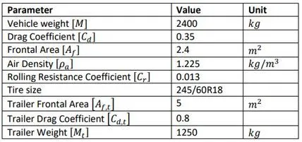
SCENARIOUS:
CASE 1: No acceleration, flat ground, no headwind, no trail.
CASE 2: No acceleration, 7% grade, no headwind, with trail.
CASE 3: Acceleration of 0.2g, no grade, headwind of 5 kmph in the vehicle direction, no trailer.
INTRODUCTION:
VEHICLE DYNAMICS:
The vehicle dynamics is the motion of the vehicle generated by the steering action, through which the vehicle is capable of independent motion. In a vehicle several forces act on it and the net or resultant force governs the motion according to the Newton's second law. The propulsion unit of the vehicle delivers the force necessary to move the vehicle forward. This force of the propulsion unit helps the vehicle to overcome the resisting forces due to gravity, air and tire resistance.
TRACTIVE EFFORT:
The effort that is required to move the vehicle or propel the vehicle. So this effort or force is generally transmitted to the ground for moving the vehicle through the driving axle and the wheels.
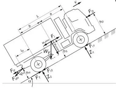
A vehicle having mass, M which is moving at velocity, v and going at a slope of angle, theta. Then, the typical tractive effort that is required to be accomplished is equal to the force required to overcome the rolling resistance that is the resistance offered due to tire resistance and the road resistance. The vehicle also has to overcome the aerodynamic drag. So this is the opposing force due to air pressure.
ROLLING RESISTANCE:
The rolling resistance of tires on hard surfaces is due to hysteresis in the tire material. On this tire a force (P), is acting at its centre. The pressure in the contact area between the tire and the ground is distributed symmetrically to the centre line and the resulting reaction force (Pz) is aligned along P.
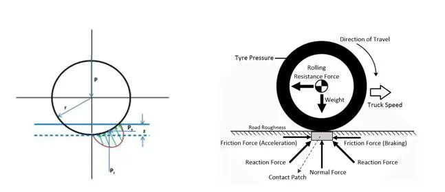
Rolling Resistance is calculated as,
F_rr= c_r *M*g* cos (theta)
When the tire rolls, the leading half of the contact area is loading and the trailing half is unloading. Thus, the pressure on the leading half is greater than the pressure on the trailing half. This phenomenon results in the ground reaction force shifting forward. The shift in the ground reaction force creates a moment that opposes rolling of the wheels.
AERODYNAMIC DRAG:
A vehicle traveling at a particular speed in air encounters a force resisting its motion. This force is known as aerodynamic drag. The main causes of aerodynamic drag are: shape drag and skin effect.
F_ad=(1/2)*rho*a*c_d*(v+v_h)^2
Where,
Rho – Air Density kg/m^3
A- Frontal area in m^2
C_d – Co-efficient of drag
V –velocity in m/s
GRADING RESISTANCE:
The force component opposes the forward motion, i.e. the grade climbing. When the vehicle goes down the grade, this force component aids the vehicle motion.
The grading resistance can be expressed as,
F_g=M*g*sin (theta)
ACCELERATION RESISTANCE:
In addition to the driving resistance occurring in steady state motion, inertial forces also occur during acceleration and braking. The total mass of the vehicle and the inertial mass of those rotating parts of the drive accelerated or braked are the factors influencing the resistance to acceleration.
F_a=M*a
CALCULATING WHEEL RADIUS:
Using the size marking of the tire we can calculate the free static wheel radius. Free means that there is no load applied on the wheel and static means that the wheel is stationary.
The main size marking of a tire is defined as:
TireWidth [mm] / AspectRatio [%] ConstructionType RimDiameter [in]
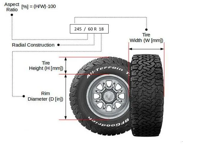
The aspect ratio (AR) is defined in percentage, as the ratio between tire sidewall height and tire width.
To calculate the radius of the wheel,
size marking - 245/60R18
Dia_wheel=(0.6*245*2)+(18*25.4);
Radis of the wheel=(Dia_wheel)/(2*1000);
Considering 97% of calculated radius
Radius,r=ra_w*0.97;
STEPS INVOLVED IN CODING:
STEP 1: Assigning the inputs to the force equations.
STEP 2: Creating a function for generic equation to evaluate forces, torque and power
STEP 3: Calling a functions to determine the forces, torque & power
STEP 4: Assigning the velocities for calculating sample calculations, v@50 km/hr
STEP 5: Tabulating the Total force, torque and power respectively for the assigned velocities.
STEP 6: Plotting the total power requirements for all 3 scenarios as a function of speed (0 to 150 km/hr).
STEP 7: Plotting the total torque requirements for all 3 scenarios as a function of speed (0 to 150 km/hr).
CODING (SAMPLE CALCULATION @ Velocity=50km/hr):
FUNCTION:
%creating function to evaluate forces, power and torque
function [F_t,P_t,T_t]=Eval(m_v,m_t,g,c_r,c_d,a,acc,rho,v,v_a,r,theta)

% calculation of forces;
f_rr=(m_v+m_t)*g*c_r*cosd(theta);   %Rolling Resistance Force
f_g=(m_v+m_t)*g*sind(theta);        %Gradient force
f_ad=0.5*a*c_d*rho*((v+v_a).^2);    %Areodynamic force
f_a=acc*g;                          %Accelaration force
% Total tractive force;
F_t=f_rr+f_g+f_ad+f_a;             %Summation of all forces
%Calculation of power;
P_t=(F_t.*v)/1000;                 %Total power
% Calculation of torque;
T_t=F_t*r;                         %Total Torque
end
MAIN CODING:
clear all
close all
clc
% Evaluation of Forces, Power & Torque by considering Vehicle and trailer
%Inputs for vehicle
m_v=2400;  %Weight of the vehicle kg
c_d=0.35;  % Drag co_efficient
a=2.4;     %Frontal area m^2
rho=1.225; %Air density kg/m^3
c_r=0.013; %Rolling resistance co_efficients
g=9.81;    %Accelaration due to gravity m/s^2
% Calculating radius of the wheel;
%size marking - 245/60R18
Dia_wheel=(0.6*245*2)+(18*25.4);
ra_w=(Dia_wheel)/(2*1000);
%Considering 97% of calculated radius
r=ra_w*0.97;
%Velocity
vel=50;     % Velocity in km/hr
v=vel/3.6;  % Converting velocity into m/s

%scenario-1:
acc1=0;    % NO accelaration
theta1=0; % No gradient - flat ground
v_a1=0;     %No head wind
m_t=0;    %No trailer

%Evaluating Force, Power & Torque;
[F_t1,P_t1,T_t1]=Eval(m_v,m_t,g,c_r,c_d,a,acc1,rho,v,v_a1,r,theta1);  % Calling a function

%scenario-2:
 acc2=0;   % NO accelaration
 grade=7;  % Grading percentage
 theta2=atand(grade/100);
 v_a2=0;     %No head wind

 %Inputs for Trailer
a_t=5;     %Trailer frontal area m^2
c_d_t=0.8; %Trailer drag co_efficient
m_t=1250;  %Trailer weight kg
%Evaluating Force, Power & Torque;
 [F_t2,P_t2,T_t2]=Eval(m_v,m_t,g,c_r,c_d_t,a_t,acc2,rho,v,v_a2,r,theta2);  % Calling a function

 %scenario-3:
 acc3=0.2;         %No accelaration
 v_a3=(5/3.6);     %No head wind
 m_t=0;  %Trailer weight kg
 theta3=0;  %No gradings

 %Evaluating Force, Power & Torque;
 [F_t3,P_t3,T_t3]=Eval(m_v,m_t,g,c_r,c_d,a,acc3,rho,v,v_a3,r,theta3);  % Calling a function

 % TABULATION OF FORCE, TORQUE AND POWER FOR VELOCITY @50 km/hr;
 T=table({'TOTAL FORCE (N)';'TOTAL TORQUE (N.M)';'TOTAL POWER(KW)'},[F_t1;T_t1;P_t1],[F_t2;T_t2;P_t2],[F_t3;T_t3;P_t3]);
 T.Properties.VariableNames={'PARAMETERS'.....
     ,'FOR SCENARIO-1 @ Velocities 50 (km/hr)'....
     , 'FOR SCENARIO-2 @ Velocities50 (km/hr)'....
     ,'FOR SCENARIO-3 @ Velocities 50(km/hr)'}
 writetable(T,'RESULT.xlsx','Sheet',1);
CODING EXPLANATION:
- Assigning the input values to the equations and converting the equations unit based on the calculations.
- Creating a function in which the input parameters are passed to determine the total force, power and torque.
- Calculating the total tractive force by the summation of all forces.
- The velocity is assigned as 50km/hr as per given condition and converted into m/s by dividing 3.6.
- The gradient angle are converetd by using atand(theta) command.
- The power is calculated by multiplying the total tractive force and velocity of the vehicle.
- The torque is calculated by multiplying the total tractive force and Radius of the wheel.
- By calling a functions to estimate the forces based on scenarios.
- With the given conditions the total power, forces and torque are founded by calling a respective functions.
- The tabulation are prepared which shows the total power, forces and torque respectively by using table command.
- The tabulation are saved as in xlsx format using pre define commands writetable.
TABULATION:

- From the tabulation it is obsorved that the differences in flat ground and slopping driving conditions.
- In scenario:1 ,The force required to propel the vehicle 405.32 N and it requires total torque of 147.67Nm wit the total power of 5.62 kw.
- In scenario:2, The gradient is added and slopping will eppects the vehicle forces, power and torque.The force required to propel the vehicle 3437.3 N and it requires total torque of 1252.3Nm wit the total power of47.74 kw.
- In scenario:3, The accelaration of vehile is considered which tends to requires a force required to propel the vehicle 428.12 N and it requires total torque of 155.98 Nm wit the total power of 5.94 kw.
- The total forces are calculated @ the velocity of 50km/hr.
- It is obsorved that the gradient needs power, forces and torque grater than the flat ground conditions.
- By different driving conditions the force, power and torque requires are been noticed.
SAMPLE CALCULATION RESULT ATTACHEMENT:
CODING (FOR TABULATION Velocities @ [25 50 75 100 125] km/hr):
clear all
close all
clc
% Evaluation of Forces, Power & Torque by considering Vehicle and trailer
%Inputs for vehicle
m_v=2400;  %Weight of the vehicle kg
c_d=0.35;  %Drag co_efficient
a=2.4;     %Frontal area m^2
rho=1.225; %Air density kg/m^3
c_r=0.013; %Rolling resistance co_efficients
g=9.81;    %Accelaration due to gravity m/s^2
% Calculating radius of the wheel;
%size marking - 245/60R18
Dia_wheel=(0.6*245*2)+(18*25.4);
ra_w=(Dia_wheel)/(2*1000);
%Considering 97% of calculated radius
r=ra_w*0.97;
%Velocity
vel=[25:25:125];     % Velocity in km/hr
v=vel/3.6;           % Converting velocity into m/s

%senario-1:
acc1=0;    % NO accelaration
theta1=0;  % No gradient - flat ground
v_a1=0;    %No head wind
m_t=0;     %No trailer

%Evaluating Force, Power & Torque;
[F_t1,P_t1,T_t1]=Eval(m_v,m_t,g,c_r,c_d,a,acc1,rho,v,v_a1,r,theta1);  % Calling a function

%scenario-2:
 acc2=0;   % NO accelaration
 grade=7;  % Grading percentage
 theta2=atand(grade/100);
 v_a2=0;   %No head wind
 %Inputs for Trailer
 a_t=5;     %Trailer frontal area m^2
 c_d_t=0.8; %Trailer drag co_efficient
 m_t=1250;  %Trailer weight kg
%Evaluating Force, Power & Torque;
 [F_t2,P_t2,T_t2]=Eval(m_v,m_t,g,c_r,c_d_t,a_t,acc2,rho,v,v_a2,r,theta2);  % Calling a function

 %scenario-3:
 acc3=0.2;       % NO accelaration
 v_a3=(5/3.6);   %No head wind
 m_t=0;          %Trailer weight kg
 theta3=0;       %No gradings

 %Evaluating Force, Power & Torque;
 [F_t3,P_t3,T_t3]=Eval(m_v,m_t,g,c_r,c_d,a,acc3,rho,v,v_a3,r,theta3);  % Calling a function

 T=table({'TOTAL FORCE';'TOTAL TORQUE';'TOTAL POWER'},[F_t1;T_t1;P_t1],[F_t2;T_t2;P_t2],[F_t3;T_t3;P_t3]);
 T.Properties.VariableNames={'PARAMETERS'.....
     ,'FOR SENARIO-1 @ Velocities (25 50 75 100 125)(km/hr)'....
     , 'FOR SENARIO-2 @ Velocities (25 50 75 100 125)(km/hr)'....
     ,'FOR SENARIO-3 @ Velocities (25 50 75 100 125)(km/hr)'}
 writetable(T,'tabulation.xlsx','Sheet',1);
CODING EXPLANATION:
- Assigning the input values to the equations and converting the equations unit based on the calculations.
- Creating a function in which the input parameters are passed to determine the total force, power and torque.
- Calculating the total tractive force by the summation of all forces.
- The velocity is assigned in the range of [ 25 50 75 100 125]km/hr as per given condition and converted into m/s by dividing 3.6.
- The power is calculated by multiplying the total tractive force and velocity of the vehicle.
- The torque is calculated by multiplying the total tractive force and Radius of the wheel.
- By calling a functions to estimate the forces based on scenarios.
- With the given conditions the total power, forces and torque are founded by calling a respective functions.
- The tabulation are prepared which shows the total power, forces and torque respectively by using table command.
- The tabulation are saved as in xlsx format using pre define commands writetable.
TABULATION:

- From the tabulation it is obsorved that the differences in flat ground and slopping driving conditions.
- The three scenarios are tabulated wit different velocity conditions.
- The total forces are calculated @ the velocity of [ 25 50 75 100 125] km/hr.
- It is obsorved that the gradient (sloppings) needs power, forces and torque grater than the flat ground conditions.
- By different driving conditions the force, power and torque requires are been noticed.
RESULT ATTACHEMENT:
CODING FOR PLOTTING:
clear all
close all
clc
% Evaluation of Total Forces, Power & Torque by considering Vehicle and trailer
%Inputs for vehicle
m_v=2400;    %Weight of the vehicle kg
c_d=0.35;  % Drag co_efficient
a=2.4;     %Frontal area m^2
rho=1.225; %Air density kg/m^3
c_r=0.013; %Rolling resistance co_efficients
g=9.81;    %Accelaration due to gravity m/s^2
% Calculating radius of the wheel;
%size marking - 245/60R18
Dia_wheel=(0.6*245*2)+(18*25.4);
ra_w=(Dia_wheel)/(2*1000);
%Considering 97% of calculated radius
r=ra_w*0.97;
%Velocity
vel=[0:150];     % Considering Velocity (0-150) km/hr
v=vel/3.6;       % Converting velocity into m/s

%% Scenario-1:
acc1=0;    % NO accelaration
theta1=0;  % No gradient - flat ground
v_a1=0;    %No head wind
m_t=0;     %No trailer

% calculation of forces;
f_rr1=(m_v+m_t)*g*c_r*cosd(theta1);   %Rolling Resistance Force
f_g1=(m_v+m_t)*g*sind(theta1);        %Gradient force
f_ad1=0.5*a*c_d*rho*((v+v_a1).^2);    %Areodynamic force
f_a1=acc1*g;                          %Accelaration force
% Total tractive force;
F_t1=f_rr1+f_g1+f_ad1+f_a1;           %Summation of all forces
%Calculation of power;
P_t1=(F_t1.*v)/1000;                  %Total power
% Calculation of torque;
T_t1=F_t1*r;                          %Total Torque

%% Scenario-2:
 acc2=0;      % NO accelaration
 grade=7;     % Grading percentage
 theta2=atand(grade/100);
 v_a2=0;      %No head wind

 %Inputs for Trailer
  a_t=5;     %Trailer frontal area m^2
  c_d_t=0.8; %Trailer drag co_efficient
  m_t=1250;  %Trailer weight kg

% calculation of forces;
f_rr2=(m_v+m_t)*g*c_r*cosd(theta2);    %Rolling Resistance Force
f_g2=(m_v+m_t)*g*sind(theta2);         %Gradient force
f_ad2=0.5*a_t*c_d_t*rho*((v+v_a2).^2); %Areodynamic force (considering trailer)
f_a2=acc2*g;                           %Accelaration force
% Total tractive force;
F_t2=f_rr2+f_g2+f_ad2+f_a2;            %Summation of all forces
%Calculation of power;
P_t2=(F_t2.*v)/1000;                   %Total power
% Calculation of torque;
T_t2=F_t2*r;                           %Total Torque

%% Scenario-3:
 acc3=0.2;      % NO accelaration
 v_a3=(5/3.6);  %No head wind
 m_t=0;         %Trailer weight kg
 theta3=0;      %No gradings

 % calculation of forces;
f_rr3=(m_v+m_t)*g*c_r*cosd(theta3);   %Rolling Resistance Force
f_g3=(m_v+m_t)*g*sind(theta3);        %Gradient force
f_ad3=0.5*a*c_d*rho*((v+v_a3).^2);    %Areodynamic force
f_a3=acc3*g;                          %Accelaration force
% Total tractive force;
F_t3=f_rr3+f_g3+f_ad3+f_a3;          %Summation of all forces
%Calculation of power;
P_t3=(F_t3.*v)/1000;                 %Total power
% Calculation of torque;
T_t3=F_t3*r;                         %Total Torque

 %% PLOTTINGS
%By considering speed (0-150km/hr)
%plotting the total power as a function of velocity
figure(1)
plot(vel,P_t1,'--','linewidth',2)
hold on
plot(vel,P_t2,'--','linewidth',2)
hold on
plot(vel,P_t3,'g','linewidth',2)
xlabel('Velocity (0-150 km/hr)')
ylabel('Power (kw)')
title('VELOCITY vs TOTAL POWER')
legend('P_t1 (f_g=0)','P_t2 (f_g=4deg)','P_t3 (f_g=0)','location','northwest')
set(gca,'fontsize',12)
%plotting the total torque as a function of velocity
figure(2)
plot(vel,T_t1,'--','linewidth',1)
hold on
plot(vel,T_t2,'--','linewidth',2)
hold on
plot(vel,T_t3,'g','linewidth',2)
xlabel('Velocity (0-150 km/hr)')
ylabel('Torque (Nm)')
title('VELOCITY vs TOTAL TORQUE')
legend('T_t1 (f_g=0)','T_t2 (f_g=4deg)','T_t3 (f_g=0)','location','northwest')
set(gca,'fontsize',12)
PLOTTING
PLOTTING FOR TOTAL POWER vs VELOCITY:
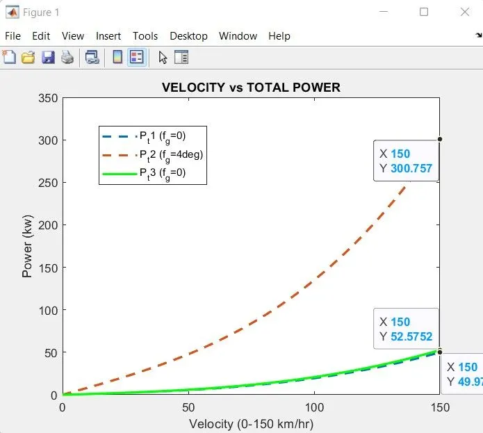
- From the graph it is obsorved that at the velocity of (0-150) km/r the differnt requirements of powers are plotted.
- In scenario:1 , There will be no accelaration and gradient are considered.
- In that the accelaration force and gradient forces are zero.
- The areodynamic and rolling resistance forces are calculates and the power required are determined using totalling of forces.
- @ 150 km/hr the vehicle requires 49.97 kw of power.
- In scenario: 2 , The trailer are considered with mass of the vehicle. Due to higher drag co-efficient and much larger projected area trailer aredynamic forces are considered.
- The gradient are assigned as 7% and slope angle of 4 deg by the inverse of tan (theta).
- It if obsorved that due to slop the vehicle with trailer requires much more higher power to propel the vehicle
- It requires 300.757 kw of power to propel at the sloppings.
- In scenario:3, There will be accelaration forces are considered and gradient forces are not considered.
- At flat ground condition the accelaration of 0.2 g are considered by which the accelaration takes place.
- In that, @ 150km/hr it requires 52.57 kw of power to tansmit the vehicle.
- From the graph it is obsorved that the gradient(@ slope) condition vehicle needs power to transmit and propel the vehicle.
- At flat ground conditions it requires lesser amount of power to propel the vehicle.
PLOTTING FOR TOTAL TORQUE vs VELOCITY:
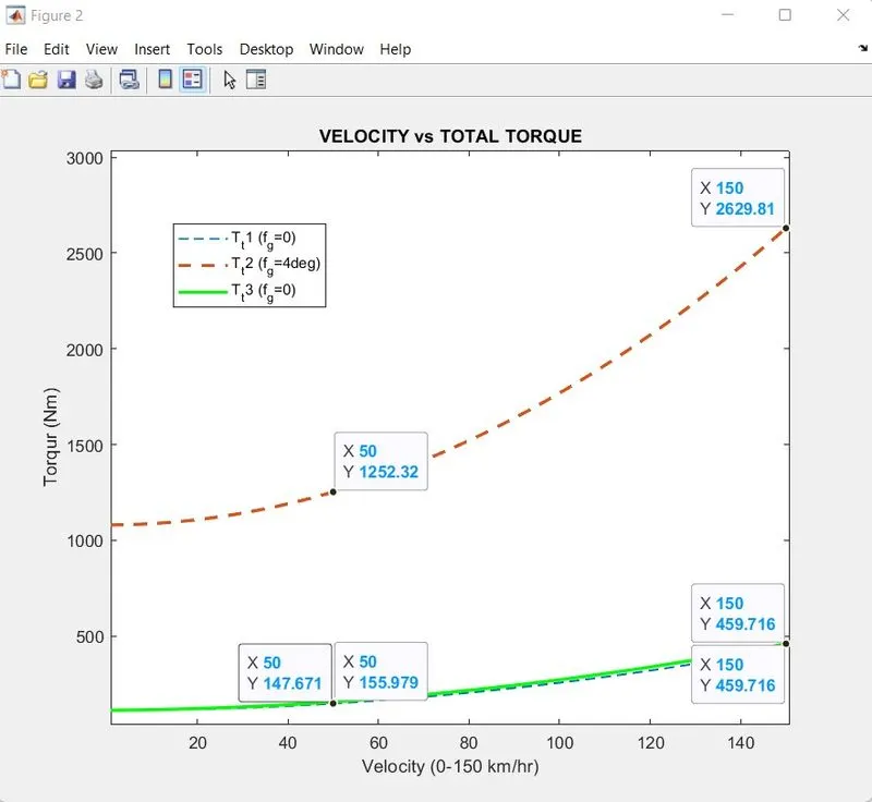
- From the graph it is obsorved that at the velocity of (0-150) km/r the differnt requirements of torque are plotted.
- In scenario:1 , There will be no accelaration and gradient are considered.
- In that the accelaration force and gradient forces are zero.
- The areodynamic and rolling resistance forces are calculates and the torque required are determined using totalling of forces.
- @ 150 km/hr the vehicle requires 432.619 Nm of torque.
- In scenario: 2 , The trailer are considered with mass of the vehicle. Due to higher drag co-efficient and much larger projected area trailer aredynamic forces are considered.
- The gradient are assigned as 7% and slope angle of 4 deg by the inverse of tan (theta).
- It if obsorved that due to slope the vehicle with trailer requires much more higher torque to propel the vehicle at initial conditions also requieres much more torque to accelarate.
- It requires 2629.81Nm of torque to propel at the sloppings.
- In scenario:3, There will be accelaration forces are considered and gradient forces are not considered.
- At flat ground condition the accelaration of 0.2 g are considered by which the accelaration takes place.
- In that, @ 150km/hr it requires 459.16 Nm of torque to propel the vehicle.
- From the graph it is obsorved that the gradient(@ slope) condition vehicle needs higher initial torque to transmit and propel the vehicle.
- Also, the variations in 50 km/hr and 150 km/hr are differentiated in plotting.
- At flat ground conditions it requires lesser amount of torque to propel the vehicle.
CONCLUSION:
- The calculation for forces,power and torque requirements for vehicle for different driving conditions are been carried out.
- The sample calculations for 50 kmph are done and tabulation are prepared.
- The tabulation for the force components, total force, along with total torque and power for 25, 50, 75, 100, 125 kmph velocities are tabulated.
- The plotting for the total power and torque requirements for all 3 scenarios as a function of speed (0 to 150 kmph) are plotted and variation and difference in power and torque are obsorved.
REFERENCES: