Week 11 - Final project
DEVELOPMENT OF A DOOR TRIM PANEL
AIM:
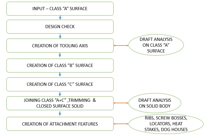
To develop a Door Trim Panel plastic componet from a class "A" Surface, by using the Closed Surface Feature to create a solid part from the surface and to create "B" Surface Attachement features with the Master section by considering the Nominal Thickness of a component.
OBJECTIVE:
- To Create a Plastic Component of Door Trim Panel using the Class 'A' surface.
- To create a Tooling axis for a class 'A' Surface, which meeting the requirement of the draft angle and to analyse the solid model.
- To create a solid model from the surface using the Closed Surface Feature.
- To create a Attachement features with reaference to the created Class B Surface.
- To follow the Master section for Nominal thickness and to follow the design rules.
- To create parting lines and check tooling feasibility.
- To create a report which explains the Draft analysis and Tooling Axis cration - colour scale varient.
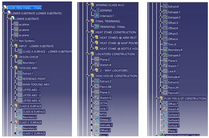
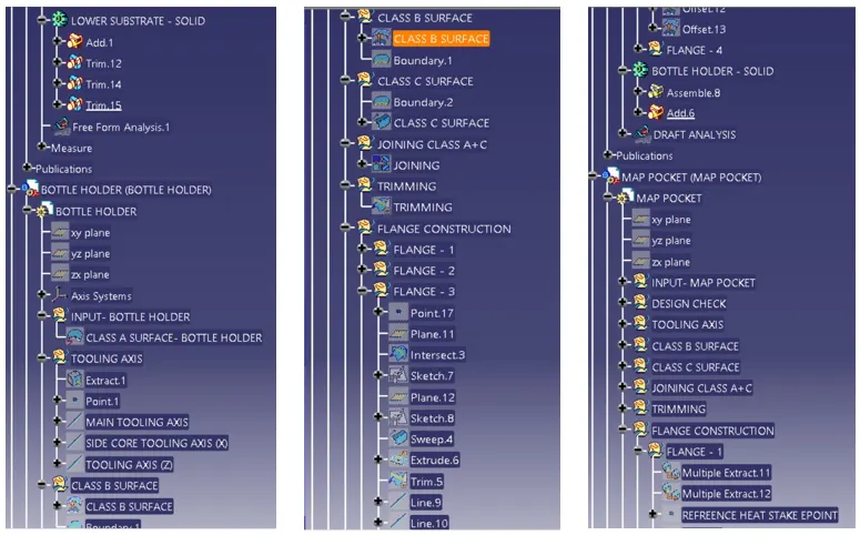
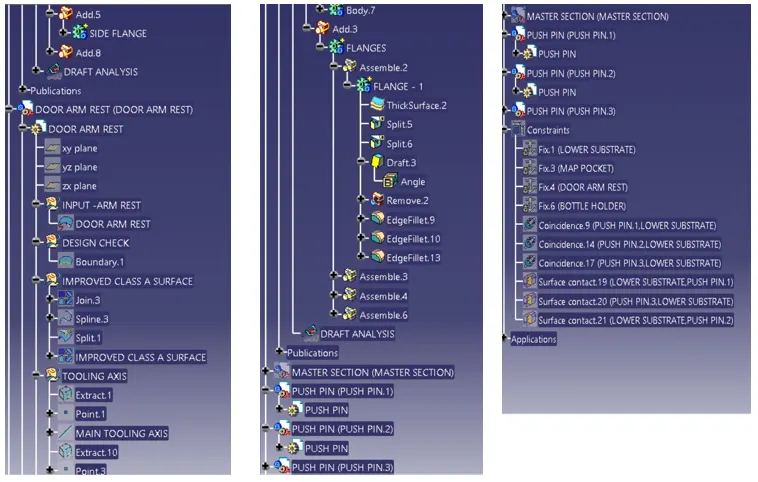
- To attach the screenshots of the expanded Tree Structure for the Geometrical Sets .
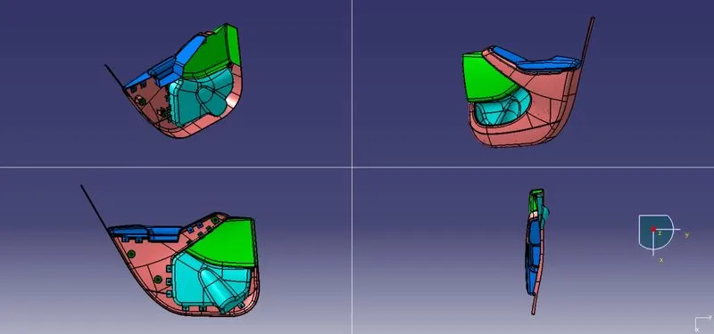
- To attach the screenshots of the 3D Part Model in different orientations.
ATTACHMENT STRATEGY:
- To use a Push Pin with Dog house for Lower substrate – Door panel attachment.
- To Use heat stakes for part to part attachment.
PART PUBLICATION:
- Class 'A' Surface.
- Tooling Axis.
- Side Core Tooling Axis.
- Class 'B' Surface.
- Class 'C' Surface.
- Solid part.
INTRODUCTION:
TOOLING DIRECTION/AXIS:
The Tooling Direction is the direction that the mold pulls apart. The mold is built in two separate pieces,
- A Cavity side.
- A Core side.
The Core pulls apart from the Cavity and that's the Dyeline or the Tooling Direction. The direction in which the mold or core and cavity opens is the tooling axis.
FEATURES OF TOOL:
- CAVITY HALF– The cavity half is the side of a tool that does not move. It is typically attached to the side of the molding machine.
- CORE HALF– The side of the tool that opens and closes with the mold machine against the cavity half. It opens when removing the part from the tool.
- COOLING LINES– Channels that allow coolant to flow throughout the tool and control the cooling of the plastic part.
- EJECTOR SYSTEM – Pins on the core half of the tool that helps push the cooled part out after molding.
- RUNNER – A flow path for the plastic resin allowing the press to inject material directly into the part cavity.
- SIDE CORE – Moving pieces within the part cavity added to allow for undercuts.
ASSEMBLY WORKBENCH:
The assembly workbenches use constraints and expressions to create relationships between the objects in model, in order to mathematically tie the objects in place.
The components are brought together and assembled in Assembly Design workbench by applying suitable parametric assembly constraints to them. The assembly constraints allow you to restrict the degrees of freedom of components on their respective work positions. The assembly files in CATIA are called Product files.
TOP - DOWN ASSEMBLY APPROACH:
Top-down Approach is a method of creating and designing the geometry all within an assembly. This is also called “in-context design” because everything is created in the context of an assembly.
BOTTOM - UP ASSEMBLY APPROACH:
Bottom-up assembly is a method of creating and designing every individual part separately. In the bottom-up approach, all the parts need to be created correctly with all the right dimensions to ensure they fit properly.
CONSTRAINTS:
The constraint is used to arrest the Degeress of Freedom (DOF) along x, y and z axis iin translational and rotational movements. Constraints can also be manually applied after the sketch geometry exists to stabilize sketch shape or position.
TYPES OF CONSTRAINTS:
(1). Dimensional Constraints.
(2). Geometrical Constraints.
(1). DIMENSIONAL CONSTRAINT:
A dimensional constraint is a constraint whose value determines geometric object measurement.
For example:
It control the length of a line, or the distance between two points.
(2). GEOMETRICAL CONSTRAINT:
A geometric constraint is a relationship that forces a limitation between one or more geometric elements.
For example:
A geometric constraint requires that two lines be parallel. If three lines are selected, or two lines and a point, these elements will automatically result parallel to each others.
CLASS A SURFACES:
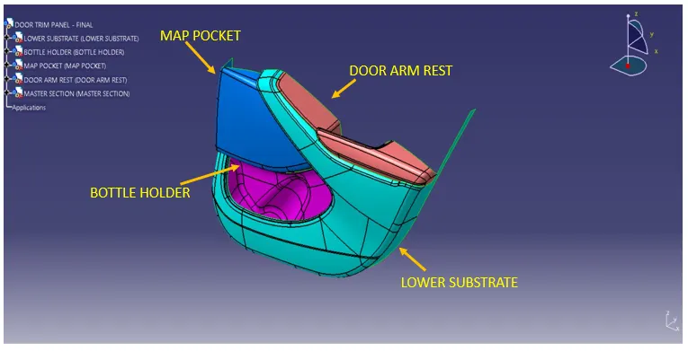
By using the Top -Down Approch, the step files are been converted into CAT part files using Assembly Workbench. The Four Different types of Class A Surfaces are been Imported into Assembly Workbench and combined together to form a CAT Product with Master Section.
METHODOLOGY:
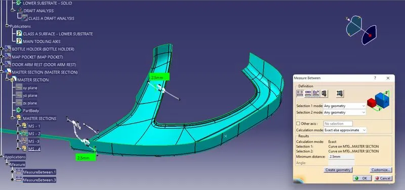
NOMINAL THICKNESS MEASUREMENT:
By using the Master Section the Nominal Thickness of the Componet are been measured.
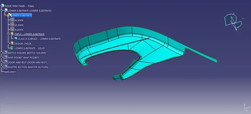
CREATING 3 -D SOLID PART - LOWER SUBSTRATE -CLOSED SURFACE FEATURE
CLASS 'A' SURFACE:
DESIGN CHECK:
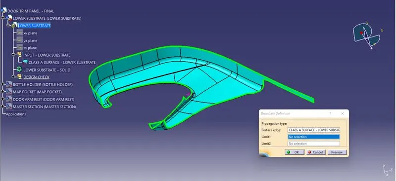
The Class A Surface are Checked Visually by using the Join Feature or by using the boundary feature the Class A surface are selceted and Disassembled the Surface to check the surface are created without the gaps. The Class A Surface should be created without the boundary Gaps. By using the Join Definition with the Merging distance of 0.001 mm the Class A surface are Joined Together to check the connectivity.
PUBLISHING THE CLASS A SURFACE:
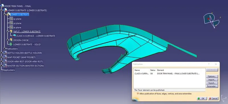
By using the Publication option the Class A Surface are Published. The Publication is used to retrive the Class A surface in the easier way to use from the Structured Tree Implementation.
CREATING TOOLING AXIS:
The Tooling for the Class A Surface are Created in the direction in which the parts are getting Ejected from the Tool. The Tooling Axis which defines the core and cavity pulls apart from the Tooling Direction.
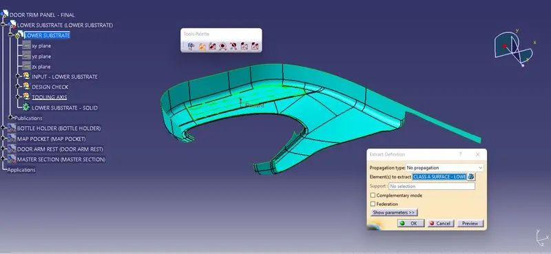
By uisng the Extract feature definition, along the x,y,z Co-ordinate System the surfaces (Surfaces are likely to see visually) are selected and extracted .
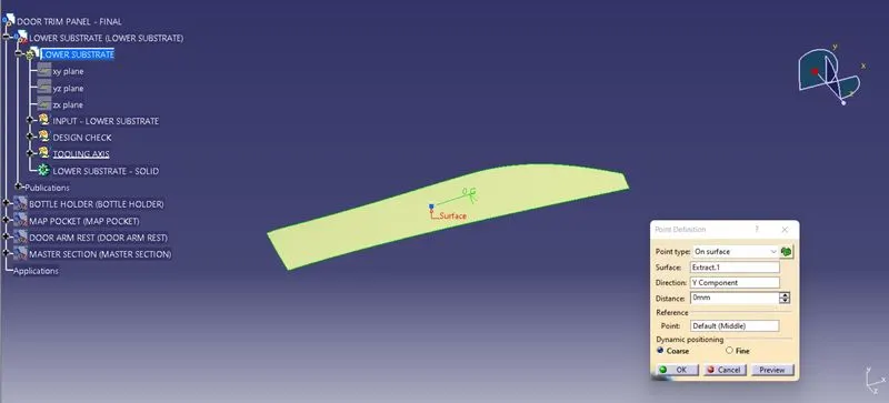
By using the Point Definition, The point has been created on surface midpoint along Y- DIrection.
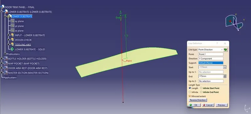
The Main Tooling Axis has been created using the line definition feature. From the line type point direction, Point has been selected and direction along Y component are selected to define the line.
MATERIAL MODES:
For the Draft Analysis, the material modes are Selected from the Shading Type.
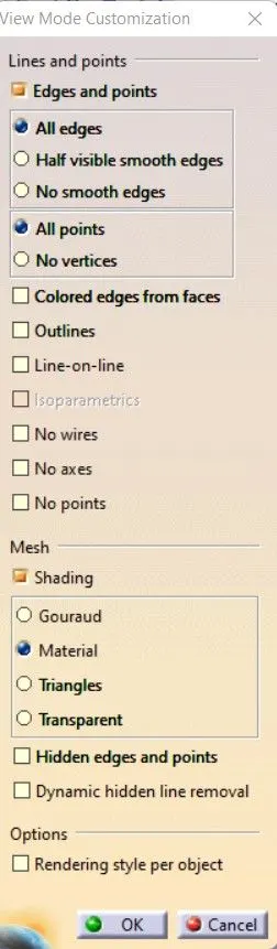
DRAFT ANAYSIS:
For a Class A Surface, The Draft analysis are to be performed in order to meeting te requirement of the draft angle to the required Tooling Axis. For Plastic component the Minimum angle required for the draft to be 3 degrees.
The Direction compass are to be selected and placed it on the Main Tooling Axis line and the comass are been locked using the lock feature in the direction.
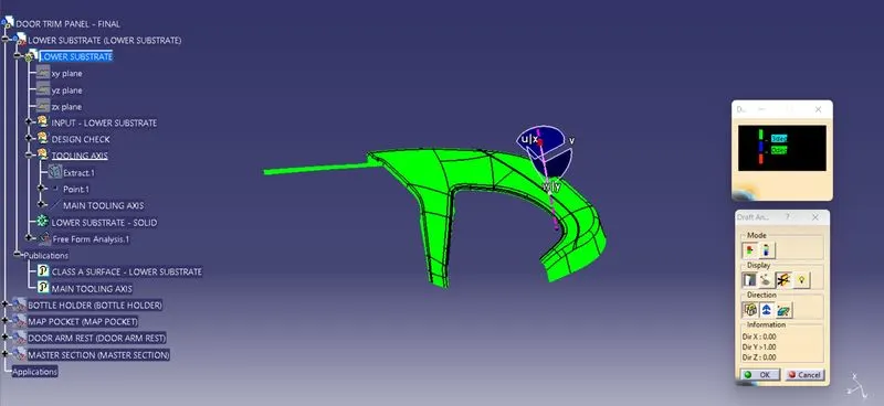
In the Display window the clour code varients are been selected, to know the range of the draft in the Class A surface. In the Display Window the colour varient shows,
- For 3 degeree - Green Colour Varient (Positive)
- For 0 degeree - Red colour varient.
- For Negative degeree- Blue colour Varient.
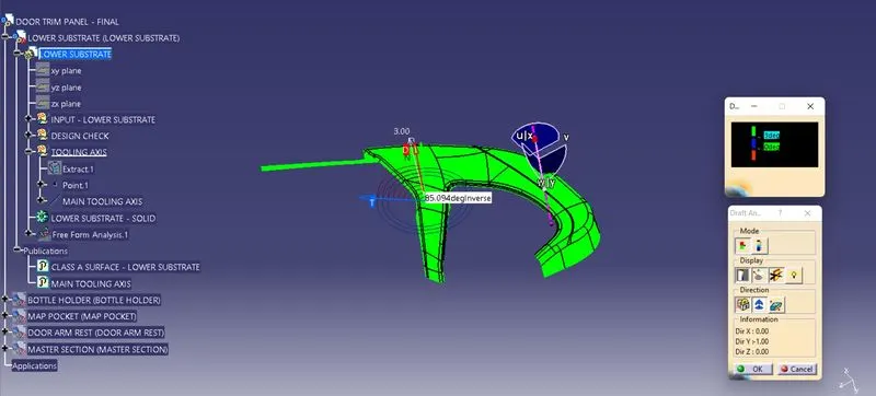
By Using the Running pointer feature in the Display the draft are been analysed for each individual points. The points perpendicular to the tolling axis are displayed as 90 Degeree Direction and other faces are analysed as 85.094 degeree angle.
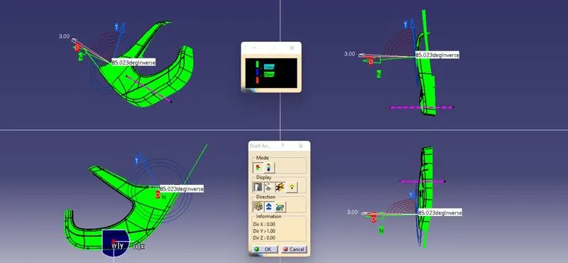
The draft Analysis are been performed in both the core and cavity side of Class A Surface. The Green colour Implies the draft angle are in the positive region. if The draft angle are been inverted the colour of the surface are implied as Blue colour.
CREATION OF CLASS 'B' SURFACE:
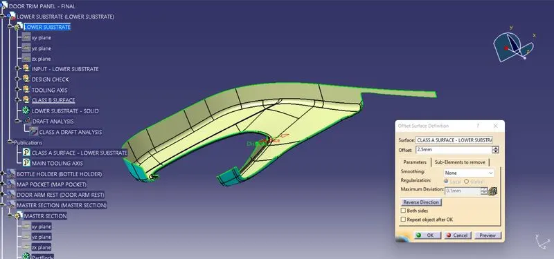
By using the Class A Surface the Class B Surface are created by offsetting to the respective length to the respective direction. By using the offset surface definition the class A Surface are been offsetted to the length of 2.5 mm to the respective direction.
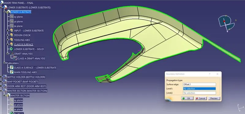
The Class B Surface are Checked Visually by using the Join Feature or by using the boundary feature the Class B surface are selceted and Disassembled the Surface to check the surface are created without the gaps and also to check the connectivity.
CREATING CLASS 'C' SURFACE:
To make the Class C Surface, the Boundaries are been Extracted from the Class A Surface. The outer Boundary, are been extracted using the Bundary feature/ EXtract definitions.
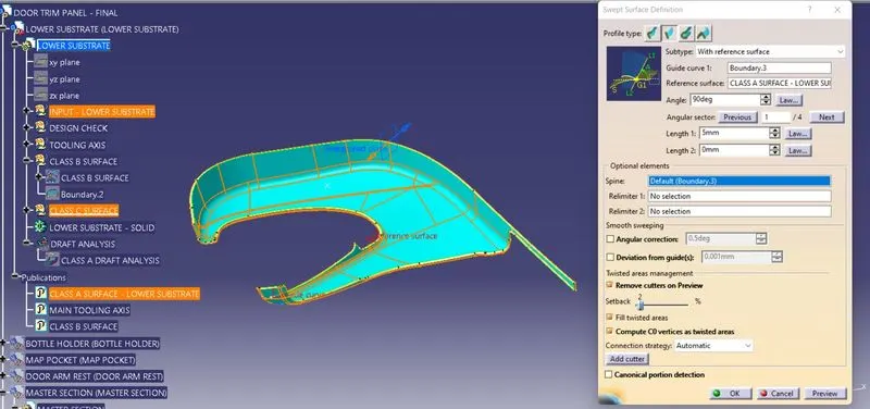
By using the Sweep surface Creation definition, The respective profile type are been selected and subtype with reference surface are been selected. In that the Guide curve are selected as the Boundary in the Class A Surface, and reference surface are selected and the Class C Surface are been created to the respective length.
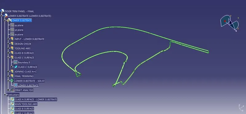
By using the Join definition feature the created Class C Surfaces are been Joined together, and also by using the Extrapolation and Trimming feature the edges are been exttapolated and trimmed together to form the class C Surfaces.
The Class C Surfaces are been created by using the sweep feature and also the Direction along the Tooling direction and the reference with the surface and guide curve are been selected to form the Class C Surfaces.
JOINING THE CLASS A AND CLASS C SURFACES:
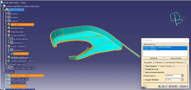
By using the Join feature the Class A and Class C Surface are Joined Together with the Merging Distance of 0.001 mm.
FINAL TRIMMING:
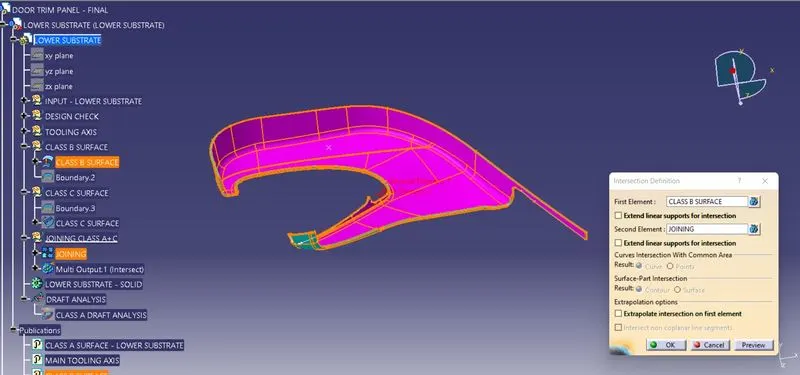
By using the Intersection feature the First element and second element are been selected to check the intersection between the created class B and Joined Class (A+C).
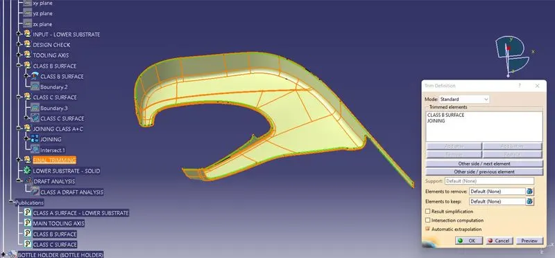
The Final Trimming Has been performed on the Class B and Joined Class A and C surfaces. The Trimming has been performed.
CLOSED SURFACE:
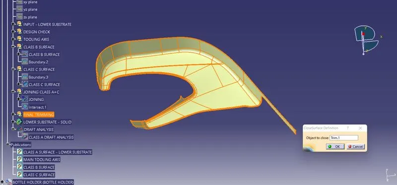
By using the close surface definition the part surface are selected to make them into solid part from the part workbench.
DRAFT ANALYSIS:
The Draft Analysis has been performed on the Fianl component created as a closed body using the part design Closed Surface Feature. For Plastic component the Minimum angle required for the daft to be 3 degrees.
The Direction compass are to be selected and placed it on the Main Tooling Axis line and the comass are been locked using the lock feature in the direction.
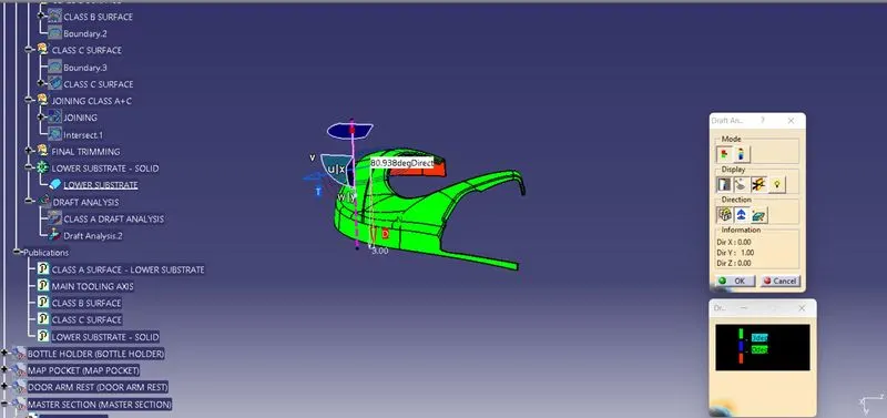
In the Display window the clour code varients are been selected, to know the range of the draft in the Class A surface. In the Display Window the colour varient shows,
- For 3 degeree - Green Colour Varient (Positive)
- For 0 degeree - Blue colour varient.
- For Negative degeree- Red colour Varient.
By Using the pointer feature in the Display the draft are been analysed for each individual points. The points perpendicular to the toling axis are displayed as 90 Degeree Direction and the Rib faces are analysed as 80.098 degeree angle.
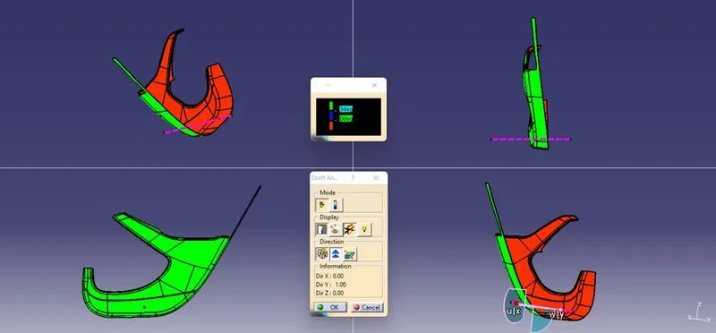
The draft Analysis are been performed in both the core and cavity side of Solid Body. The Green colour Implies the draft angle are in the positive region. if The draft angle are been inverted the colour of the surface are implied as Blue colour.
CREATING 3 -D SOLID PART - MAP POCKET - CLOSED SURFACE FEATURE
CLASS 'A' SURFACE:
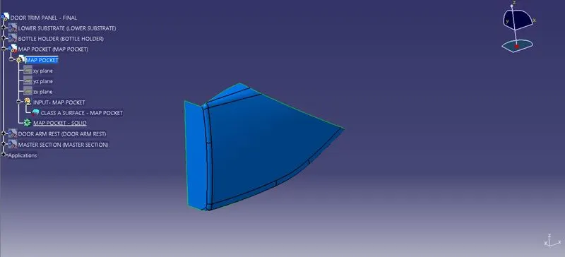
DESIGN CHECK:
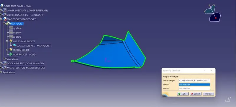
The Class A Surface are Checked Visually by using the Join Feature or by using the boundary feature the Class A surface are selceted and Disassembled the Surface to check the surface are created without the gaps. The Class A Surface should be created without the boundary Gaps. By using the Join Definition with the Merging distance of 0.001 mm the Class A surface are Joined Together to check the connectivity.
PUBLISHING THE CLASS A SURFACE:
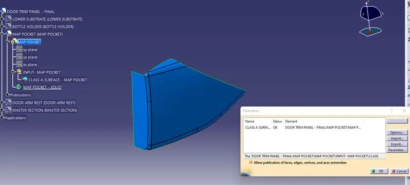
By using the Publication option the Class A Surface are Published. The Publication is used to retrive the Class A surface in the easier way to use from the Structured Tree Implementation.
CREATING TOOLING AXIS:
The Tooling for the Class A Surface are Created in the direction in which the parts are getting Ejected from the Tool. The Tooling Axis which defines the core and cavity pulls apart from the Tooling Direction.
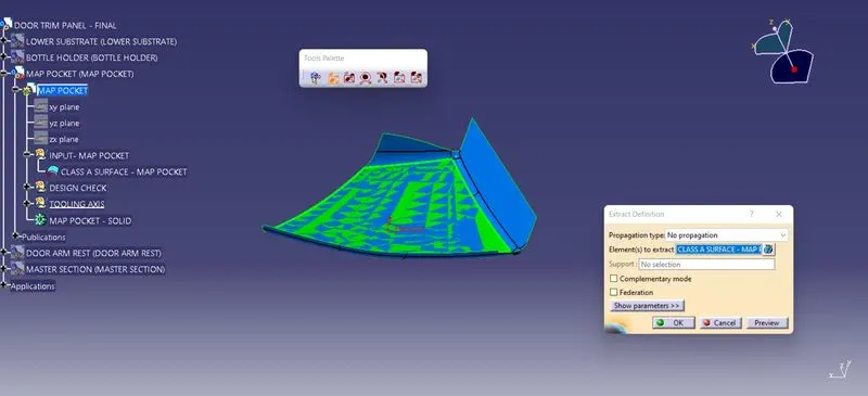
By using the Extract feature definition, along the x,y,z Co-ordinate System the surfaces (Surfaces are likely to see visually) are selected and extracted .
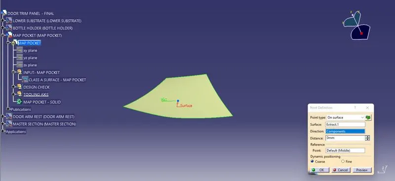
By using the Point Definition, The point has been created on surface midpoint along Y- DIrection.
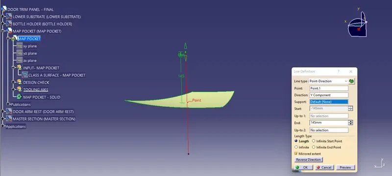
The Main Tooling Axis has been created using the line definition feature. From the line type point direction, Point has been selected and direction along Y component are selected to define the line.
MATERIAL MODES:
For the Draft Analysis, the material modes are Selected from the Shading Type.
DRAFT ANAYSIS:
For a Class A Surface, The Draft analysis are to be performed in order to meeting the requirement of the draft angle to the required Tooling Axis. For Plastic component the Minimum angle required for the draft to be 3 degrees.
The Direction compass are to be selected and placed it on the Main Tooling Axis line and the comass are been locked using the lock feature in the direction.
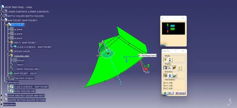
In the Display window the clour code varients are been selected, to know the range of the draft in the Class A surface. In the Display Window the colour varient shows,
- For 3 degeree - Green Colour Varient (Positive)
- For 0 degeree - Red colour varient.
- For Negative degeree- Blue colour Varient.
By Using the Running pointer feature in the Display the draft are been analysed for each individual points. The points perpendicular to the tolling axis are displayed as 90 Degeree Direction and other faces are analysed as 81.965 degere angle.
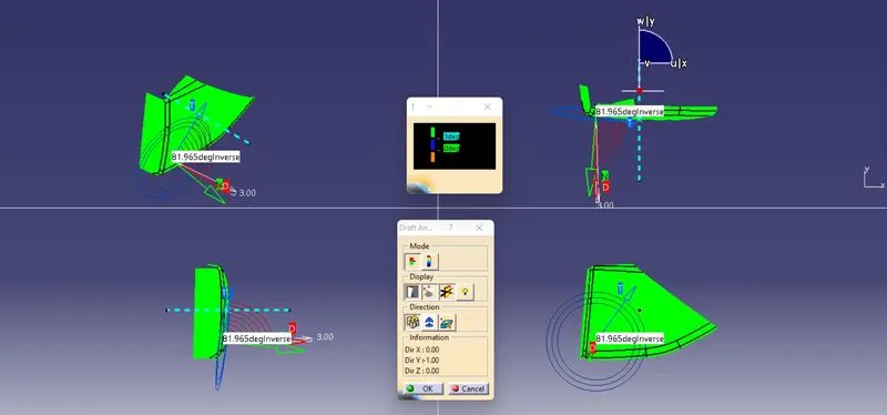
The draft Analysis are been performed in both the core and cavity side of Class A Surface. The Green colour Implies the draft angle are in the positive region. if The draft angle are been inverted the colour of the surface are implied as Blue colour.
CREATION OF CLASS 'B' SURFACE:
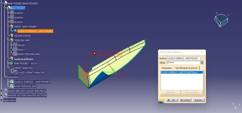
By using the Class A Surface the Class B Surface are created by offsetting to the respective length to the respective direction. By using the offset surface definition the class A Surface are been offsetted to the length of 2.5 mm to the respective direction.
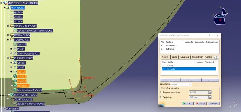
By using the Spline and Multi section feature definition the Splines are created tangent to the relative surfaces and using Multi section Surfaces the guides and sections are been selected and surfaces are formed.
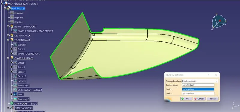
By using the Join feature the Class B surfaces and Multi section surfaces are been Joined Together. The Class B Surface are Checked Visually by using the Join Feature or by using the boundary feature the Class B surface are selceted and Disassembled the Surface to check the surface are created without the gaps and also to check the connectivity.
CREATING CLASS 'C' SURFACE:
To make the Class C Surface, the Boundaries are been Extracted from the Class A Surface. The outer Boundary, are been extracted using the Bundary feature/ Extract definitions.
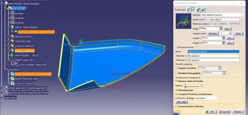
By using the Sweep surface Creation definition, The respective profile type are been selected and subtype with reference surface are been selected. In that the Guide curve are selected as the Boundary in the Class A Surface, and reference surface are selected and the Class C Surface are been created to the respective length.
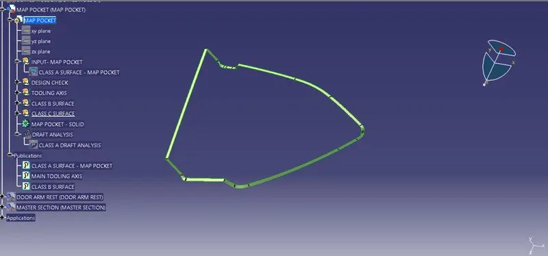
By using the Join definition feature the created Class C Surfaces are been Joined together, and also by using the Extrapolation and Trimming feature the edges are been exttapolated and trimmed together to form the class C Surfaces.
The Class C Surfaces are been created by using the sweep feature and also the Direction along the Tooling direction and the reference with the surface and guide curve are been selected to form the Class C Surfaces.
JOINING THE CLASS A AND CLASS C SURFACES:
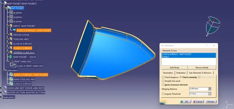
By using the Join feature the Class A and Class C Surface are Joined Together with the Merging Distance of 0.001 mm.
FINAL TRIMMING:
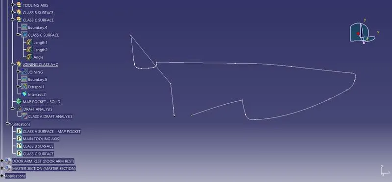
By using the Intersection feature the First element and second element are been selected to check the intersection between the created class B and Joined Class (A+C). The Unmatched surafaces are Extrapolated in the Class B surfaces.
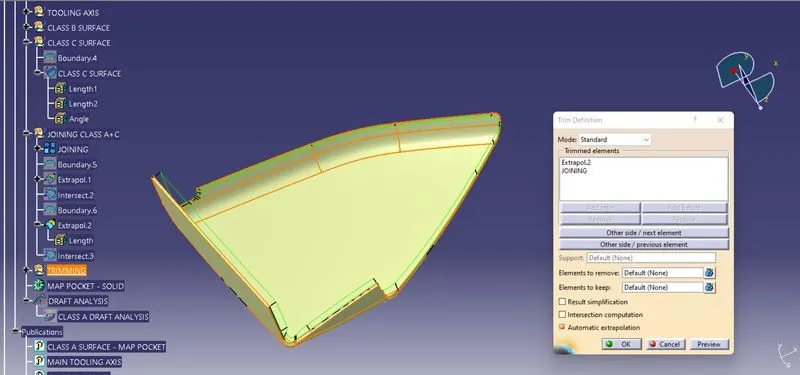
The Final Trimming Has been performed on the Class B and Joined Class A and C surfaces. The Trimming has been performed.
CLOSED SURFACE:
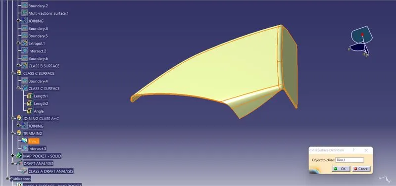
By using the close surface definition the part surface are selected to make them into solid part from the part workbench.
DRAFT ANALYSIS:
The Draft Analysis has been performed on the Fianl component created as a closed body using the part design Closed Surface Feature. For Plastic component the Minimum angle required for the daft to be 3 degrees.
The Direction compass are to be selected and placed it on the Main Tooling Axis line and the comass are been locked using the lock feature in the direction.
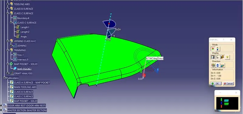
In the Display window the clour code varients are been selected, to know the range of the draft in the Class A surface. In the Display Window the colour varient shows,
- For 3 degeree - Green Colour Varient (Positive)
- For 0 degeree - Blue colour varient.
- For Negative degeree- Red colour Varient.
By Using the pointer feature in the Display the draft are been analysed for each individual points. The points perpendicular to the toling axis are displayed as 90 Degeree Direction and the Rib faces are analysed as 80.098 degeree angle.
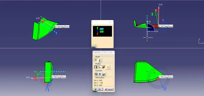
The draft Analysis are been performed in both the core and cavity side of Solid Body. The Green colour Implies the draft angle are in the positive region. if The draft angle are been inverted the colour of the surface are implied as Blue colour.
CREATING 3 -D SOLID PART - BOTTLE HOLDER - CLOSED SURFACE FEATURE
CLASS 'A' SURFACE:
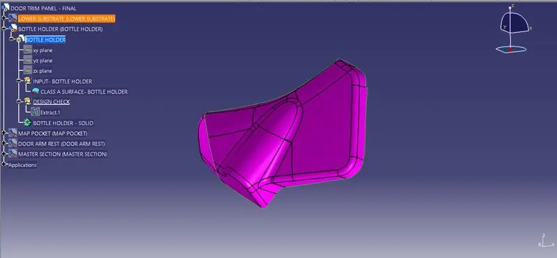
DESIGN CHECK:
The Class A Surface are Checked Visually by using the Join Feature or by using the boundary feature the Class A surface are selceted and Disassembled the Surface to check the surface are created without the gaps. The Class A Surface should be created without the boundary Gaps. By using the Join Definition with the Merging distance of 0.001 mm the Class A surface are Joined Together to check the connectivity.
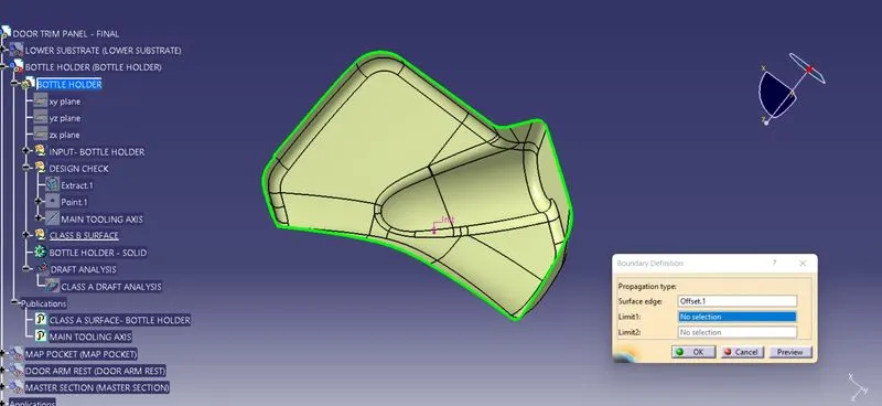
PUBLISHING THE CLASS A SURFACE:
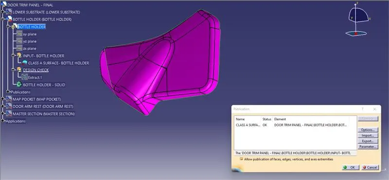
By using the Publication option the Class A Surface are Published. The Publication is used to retrive the Class A surface in the easier way to use from the Structured Tree Implementation.
CREATING TOOLING AXIS:
The Tooling for the Class A Surface are Created in the direction in which the parts are getting Ejected from the Tool. The Tooling Axis which defines the core and cavity pulls apart from the Tooling Direction.
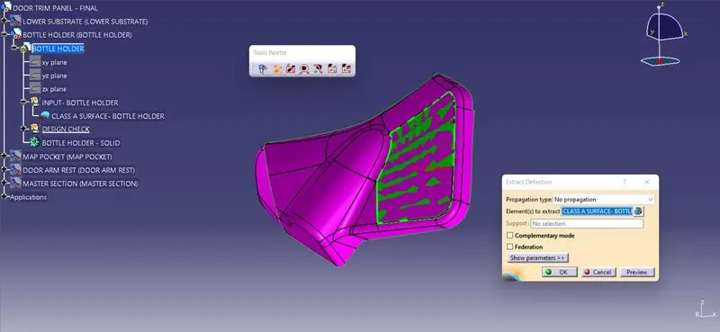
By using the Extract feature definition, along the x,y,z Co-ordinate System the surfaces (Surfaces are likely to see visually) are selected and extracted .
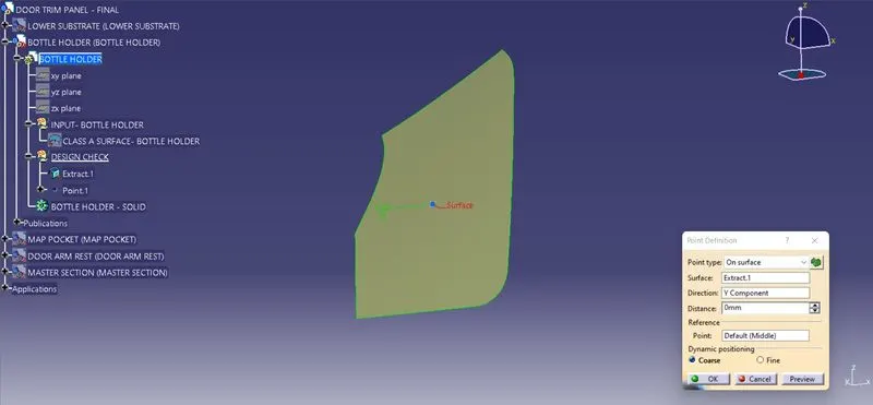
By using the Point Definition, The point has been created on surface midpoint along Y- DIrection.
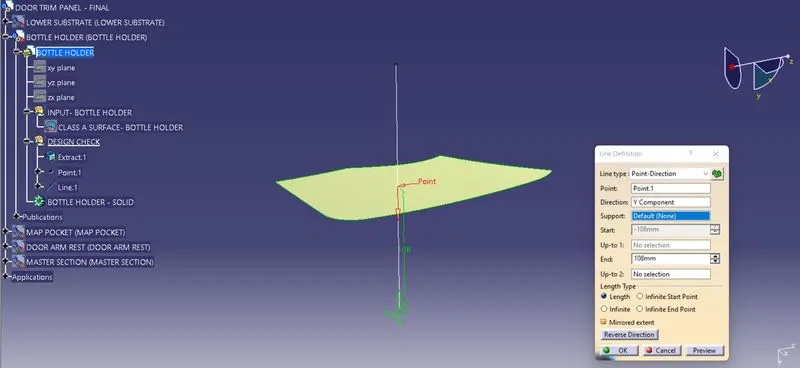
The Main Tooling Axis has been created using the line definition feature. From the line type point direction, Point has been selected and direction along Y component are selected to define the line.
MATERIAL MODES:
For the Draft Analysis, the material modes are Selected from the Shading Type.
DRAFT ANAYSIS:
For a Class A Surface, The Draft analysis are to be performed in order to meeting te requirement of the draft angle to the required Tooling Axis. For Plastic component the Minimum angle required for the draft to be 3 degrees.
The Direction compass are to be selected and placed it on the Main Tooling Axis line and the comass are been locked using the lock feature in the direction.
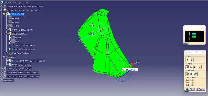
In the Display window the clour code varients are been selected, to know the range of the draft in the Class A surface. In the Display Window the colour varient shows,
- For 3 degeree - Green Colour Varient (Positive)
- For 0 degeree - Red colour varient.
- For Negative degeree- Blue colour Varient.
By Using the Running pointer feature in the Display the draft are been analysed for each individual points. The points perpendicular to the tolling axis are displayed as 90 Degeree Direction and other faces are analysed as 73.484 degeree angle.
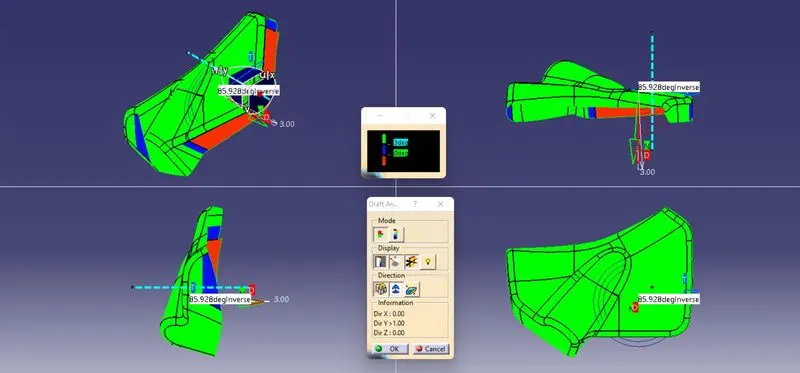
The draft Analysis are been performed in both the core and cavity side of Class A Surface. The Green colour Implies the draft angle are in the positive region. if The draft angle are been inverted the colour of the surface are implied as Blue colour.
CREATION OF CLASS 'B' SURFACE:
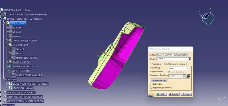
By using the Class A Surface the Class B Surface are created by offsetting to the respective length to the respective direction. By using the offset surface definition the class A Surface are been offsetted to the length of 2.5 mm to the respective direction.
By using the Join feature the Class B surfaces and Multi section surfaces are been Joined Together. The Class B Surface are Checked Visually by using the Join Feature or by using the boundary feature the Class B surface are selceted and Disassembled the Surface to check the surface are created without the gaps and also to check the connectivity.
CREATING CLASS 'C' SURFACE:
To make the Class C Surface, the Boundaries are been Extracted from the Class A Surface. The outer Boundary, are been extracted using the Bundary feature/ Extract definitions.
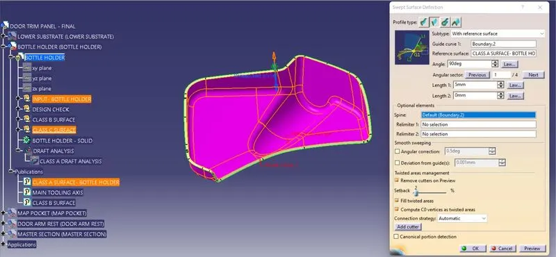
By using the Sweep surface Creation definition, The respective profile type are been selected and subtype with reference surface are been selected. In that the Guide curve are selected as the Boundary in the Class A Surface, and reference surface are selected and the Class C Surface are been created to the respective length.
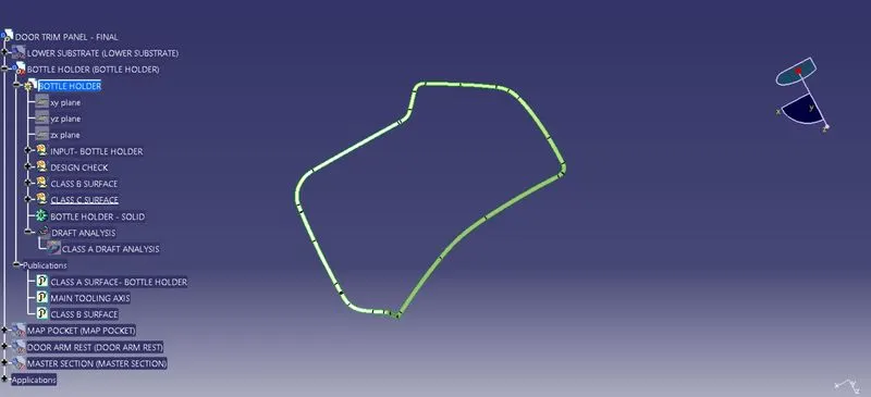
By using the Join definition feature the created Class C Surfaces are been Joined together, and also by using the Extrapolation and Trimming feature the edges are been exttapolated and trimmed together to form the class C Surfaces.
The Class C Surfaces are been created by using the sweep feature and also the Direction along the Tooling direction and the reference with the surface and guide curve are been selected to form the Class C Surfaces.
JOINING THE CLASS A AND CLASS C SURFACES:
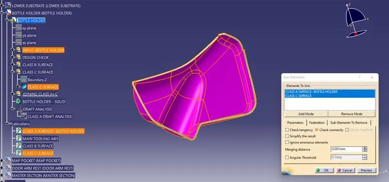
By using the Join feature the Class A and Class C Surface are Joined Together with the Merging Distance of 0.001 mm.
FINAL TRIMMING:
By using the Intersection feature the First element and second element are been selected to check the intersection between the created class B and Joined Class (A+C). The Unmatched surafaces are Extrapolated in the Class B surfaces.
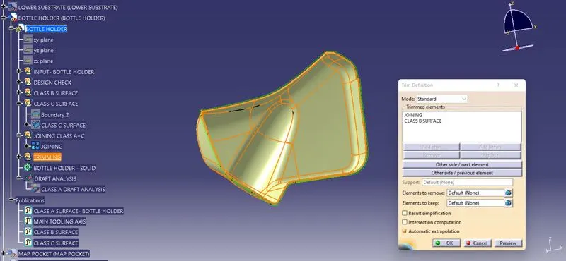
The Final Trimming Has been performed on the Class B and Joined Class A and C surfaces. The Trimming has been performed.
CLOSED SURFACE:
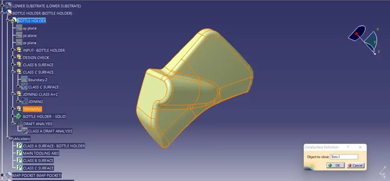
By using the close surface definition the part surface are selected to make them into solid part from the part workbench.
DRAFT ANALYSIS:
The Draft Analysis has been performed on the Fianl component created as a closed body using the part design Closed Surface Feature. For Plastic component the Minimum angle required for the daft to be 3 degrees.
The Direction compass are to be selected and placed it on the Main Tooling Axis line and the comass are been locked using the lock feature in the direction.
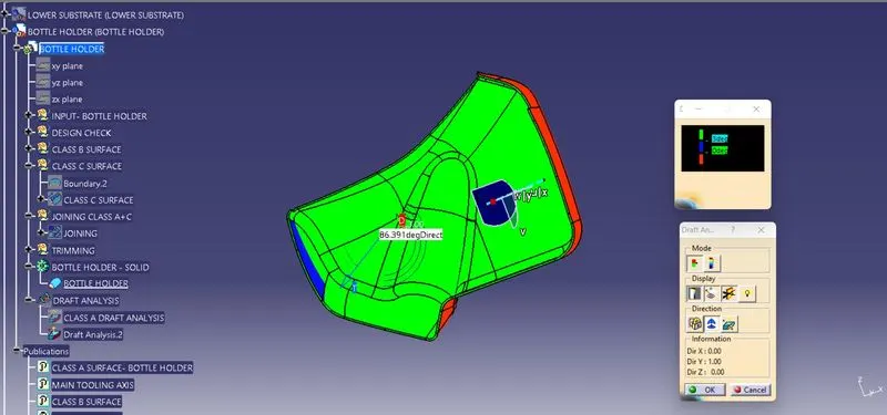
In the Display window the clour code varients are been selected, to know the range of the draft in the Class A surface. In the Display Window the colour varient shows,
- For 3 degeree - Green Colour Varient (Positive)
- For 0 degeree - Blue colour varient.
- For Negative degeree- Red colour Varient.
By Using the pointer feature in the Display the draft are been analysed for each individual points. The points perpendicular to the toling axis are displayed as 90 Degeree Direction and the Rib faces are analysed as 80.098 degeree angle.
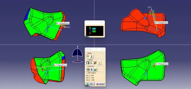
The draft Analysis are been performed in both the core and cavity side of Solid Body. The Green colour Implies the draft angle are in the positive region. if The draft angle are been inverted the colour of the surface are implied as Blue colour.
CREATING 3 -D SOLID PART - DOOR ARM REST - CLOSED SURFACE FEATURE
CLASS 'A' SURFACE:
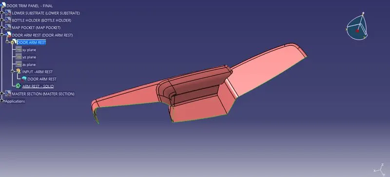
DESIGN CHECK:
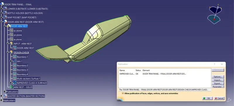
The Class A Surface are Checked Visually by using the Join Feature or by using the boundary feature the Class A surface are selceted and Disassembled the Surface to check the surface are created without the gaps. The Class A Surface should be created without the boundary Gaps. By using the Join Definition with the Merging distance of 0.001 mm the Class A surface are Joined Together to check the connectivity.
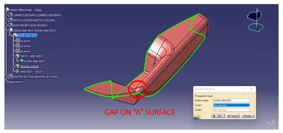
During the Design check on class A surface Founded a Gap on the Arm Rest Surface. The Class Surface are to be Improved without Design Gaps.
CREATING TOOLING AXIS:
The Tooling for the Class A Surface are Created in the direction in which the parts are getting Ejected from the Tool. The Tooling Axis which defines the core and cavity pulls apart from the Tooling Direction.
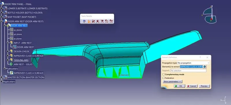
By using the Extract feature definition, along the x,y,z Co-ordinate System the surfaces (Surfaces are likely to see visually) are selected and extracted .
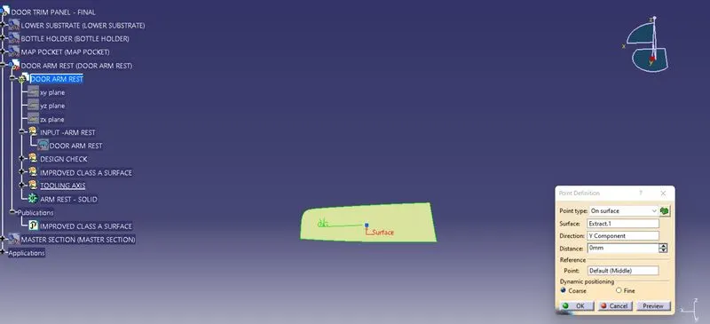
By using the Point Definition, The point has been created on surface midpoint along Y- DIrection.
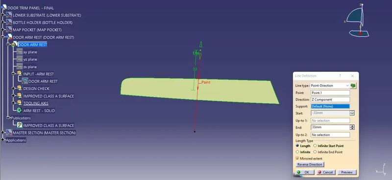
The Main Tooling Axis has been created using the line definition feature. From the line type point direction, Point has been selected and direction along Y component are selected to define the line.
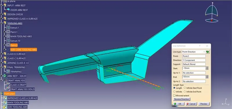
The Side Core Tooling Axis has been created using the line definition feature. From the line type point direction, Point has been selected and direction along plane are selected to define the line.
MATERIAL MODES:
For the Draft Analysis, the material modes are Selected from the Shading Type.
DRAFT ANAYSIS:
For a Class A Surface, The Draft analysis are to be performed in order to meeting te requirement of the draft angle to the required Tooling Axis. For Plastic component the Minimum angle required for the draft to be 3 degrees.
The Direction compass are to be selected and placed it on the Main Tooling Axis line and the comass are been locked using the lock feature in the direction.
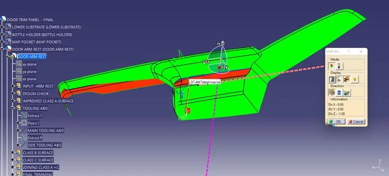
In the Display window the clour code varients are been selected, to know the range of the draft in the Class A surface. In the Display Window the colour varient shows,
- For 3 degeree - Green Colour Varient (Positive)
- For 0 degeree - Red colour varient.
- For Negative degeree- Blue colour Varient.
The Side core Tooling axis Is to Created to clear the draft on the Undercutted surfaces. By Using the Running pointer feature in the Display the draft are been analysed for each individual points. The points perpendicular to the tolling axis are displayed as 90 Degeree Direction and other faces are analysed as 37.745 degere angle.
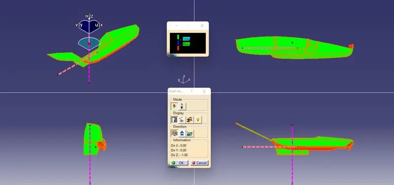
The draft Analysis are been performed in both the core and cavity side of Class A Surface.
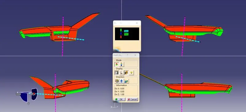
The Green colour Implies the draft angle are in the positive region. if The draft angle are been inverted the colour of the surface are implied as Blue colour.
CREATION OF CLASS 'B' SURFACE:
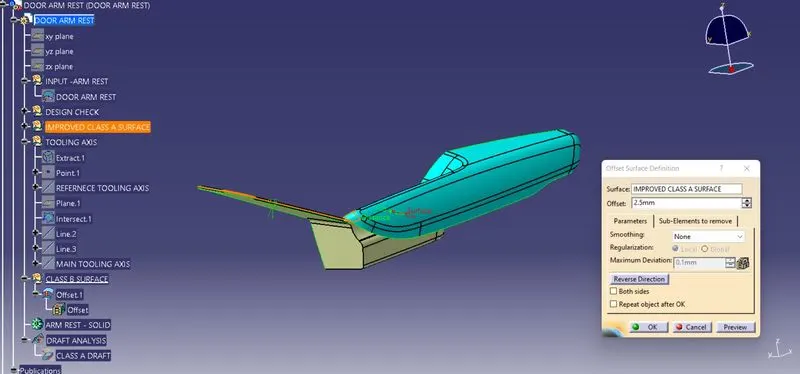
By using the Class A Surface the Class B Surface are created by offsetting to the respective length to the respective direction. By using the offset surface definition the class A Surface are been offsetted to the length of 2.5 mm to the respective direction.
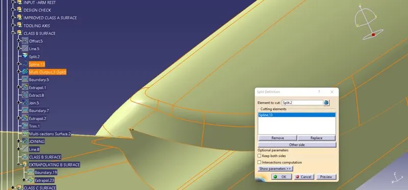
After Offsetting the Class B surface, the pathes are been cleared using the line and split features to create a proper class B Surfaces.
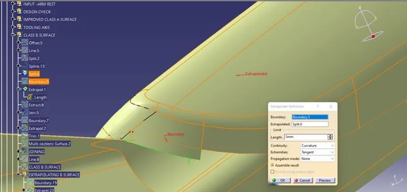
By using the Extrapolate feature the Extracted surfaces are been extrapolated by selcting the boundaries and also the extrpolands. The continuty for the extrapolation are selected as curvature and propogation mode are been selected as Point. By selecting the features the boundaries are been extrapolated to the respective length provided.
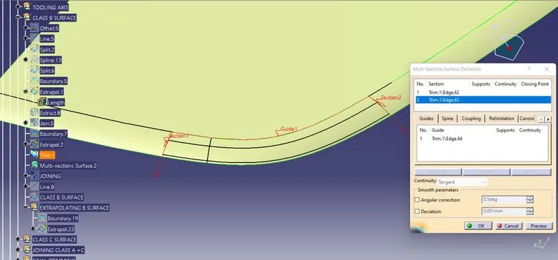
By using the Spline and Multi section feature definition the Splines are created tangent to the relative surfaces and using Multi section Surfaces the guides and sections are been selected and surfaces are formed.
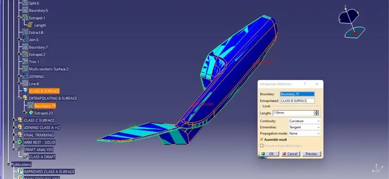
By using the Join feature the Class B surfaces and Multi section surfaces are been Joined Together. The Class B Surface are Checked Visually by using the Join Feature or by using the boundary feature the Class B surface are selceted and Disassembled the Surface to check the surface are created without the gaps and also to check the connectivity.
CREATING CLASS 'C' SURFACE:
To make the Class C Surface, the Boundaries are been Extracted from the Class A Surface. The outer Boundary, are been extracted using the Bundary feature/ Extract definitions.
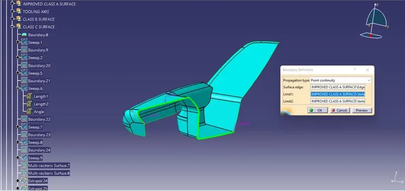
By using the Boundary definition the Certain areas are been selected as a boundary using Limits (1&2).
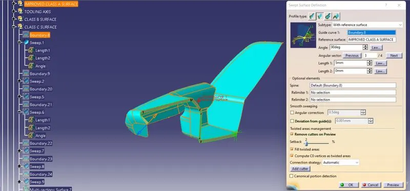
By using the Sweep surface Creation definition, The respective profile type are been selected and subtype with reference surface are been selected. In that the Guide curve are selected as the Boundary in the Class A Surface, and reference surface are selected and the Class C Surface are been created to the respective length.
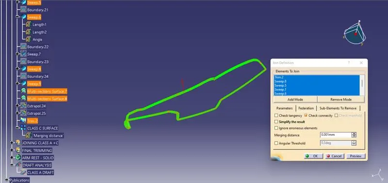
By using the Join definition feature the created Class C Surfaces are been Joined together, and also by using the Extrapolation and Trimming feature the edges are been exttapolated and trimmed together to form the class C Surfaces.
The Class C Surfaces are been created by using the sweep feature and also the Direction along the Tooling direction and the reference with the surface and guide curve are been selected to form the Class C Surfaces.
JOINING THE CLASS A AND CLASS C SURFACES:
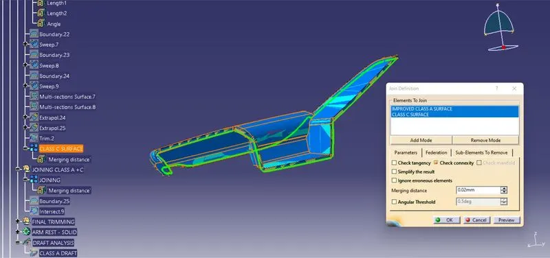
By using the Join feature the Class A and Class C Surface are Joined Together with the Merging Distance of 0.001 mm.
FINAL TRIMMING:
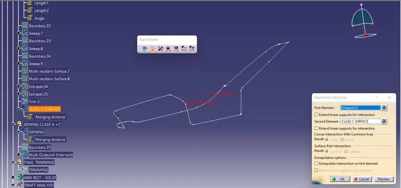
By using the Intersection feature the First element and second element are been selected to check the intersection between the created class B and Joined Class (A+C). The Unmatched surafaces are Extrapolated in the Class B surfaces.
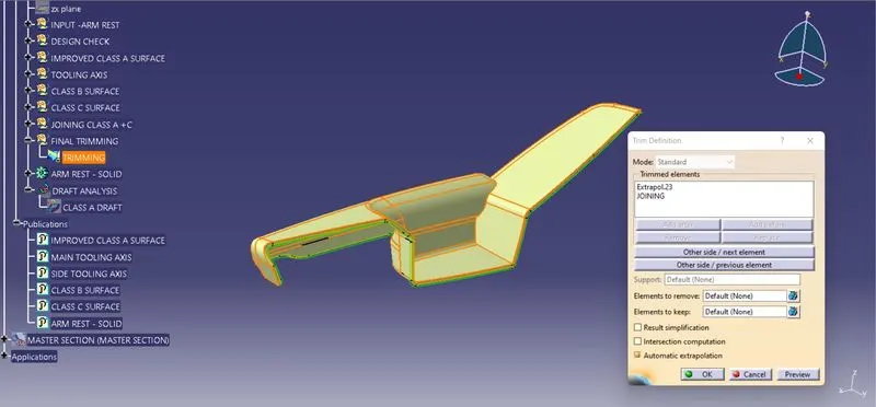
The Final Trimming Has been performed on the Class B and Joined Class A and C surfaces. The Trimming has been performed.
CLOSED SURFACE:
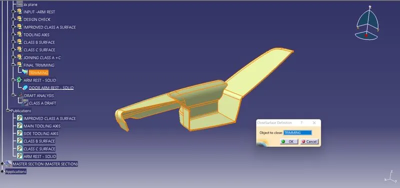
By using the close surface definition the part surface are selected to make them into solid part from the part workbench.
DRAFT ANALYSIS:
The Draft Analysis has been performed on the Fianl component created as a closed body using the part design Closed Surface Feature. For Plastic component the Minimum angle required for the daft to be 3 degrees.
The Direction compass are to be selected and placed it on the Main Tooling Axis line and the comass are been locked using the lock feature in the direction.
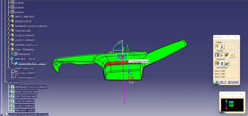
In the Display window the clour code varients are been selected, to know the range of the draft in the Class A surface. In the Display Window the colour varient shows,
- For 3 degeree - Green Colour Varient (Positive)
- For 0 degeree - Blue colour varient.
- For Negative degeree- Red colour Varient.
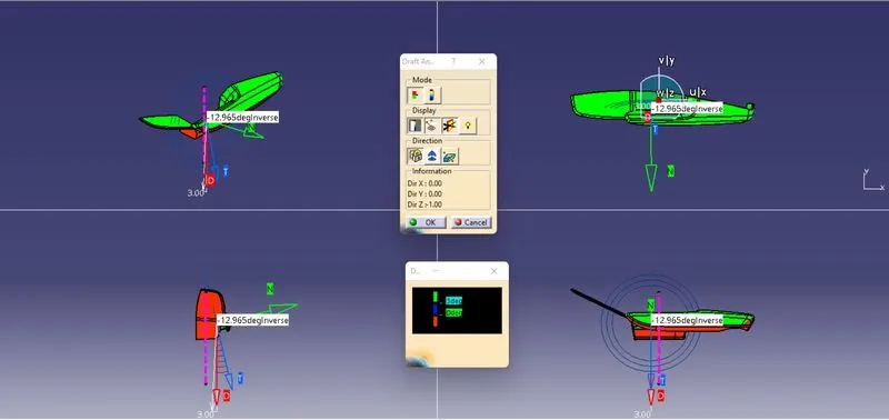
By Using the pointer feature in the Display the draft are been analysed for each individual points. The points perpendicular to the toling axis are displayed as 90 Degeree Direction and the Rib faces are analysed as 12.965 degeree angle.
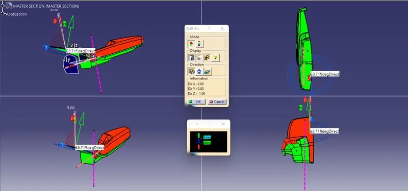
The draft Analysis are been performed in both the core and cavity side of Solid Body. The Green colour Implies the draft angle are in the positive region. if The draft angle are been inverted the colour of the surface are implied as Blue colour.
CREATING "B" SURFACE ATTACHMENT FEATURE DESIGN USING MASTER SECION
HEAT STAKE DESIGN:
Heat staking also known as thermoplastic staking is the process of joining two Similar/dissimilar materials together. In heat staking use local heating and cooling to raise the temperature of plastic components and allow plastic reforming to be carried out.
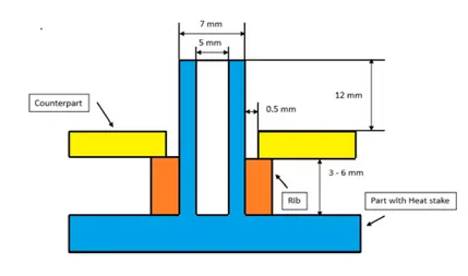
MEASUREMENT:
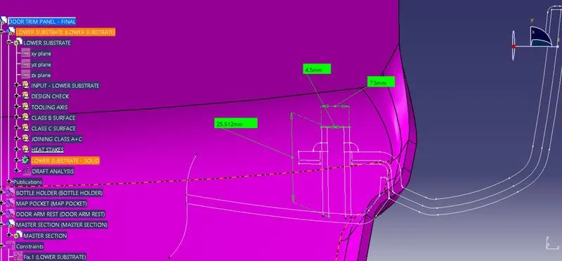
CONSTRUCTION OF HEAT STAKES:
By using the Master section the Inner Dia, Outer Dia and Length of the Heat stakes are been measured.
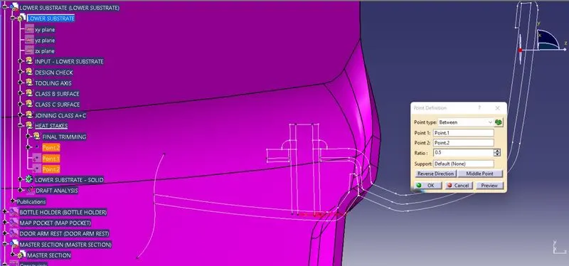
By using the point definition feature the Points are created between Two points to make the center point @ the heat stakes.
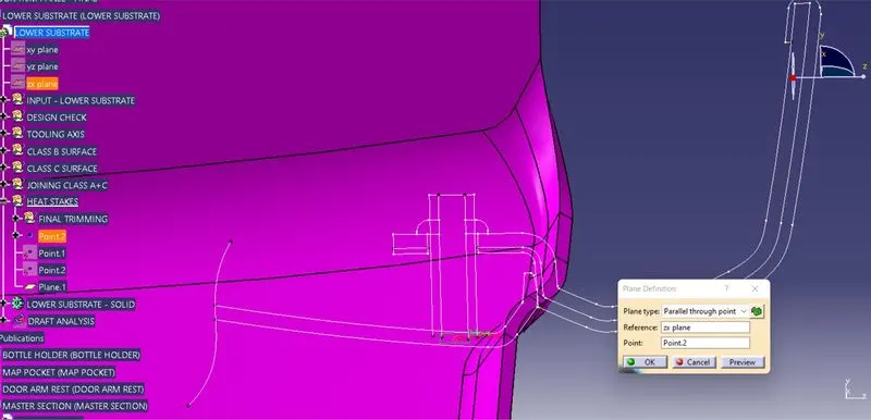
By using the plane definition feature the Respective planes are been created @ the point reference. By using the plane and the Projection point, Positioned sketch are been created to sketch the profile of the heat stake with respective ID and OD.
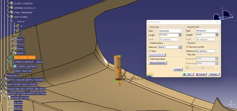
By using the Pad definition the 2 - D sketches are been extruded and the first and second limit are been definied to the respective length to the respective direction.
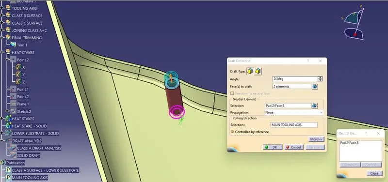
By using the draft definition the faces are been selected to draft and the pulling dircetion are been selected as a Main tooling axis also the neutral element to draft are been selected.
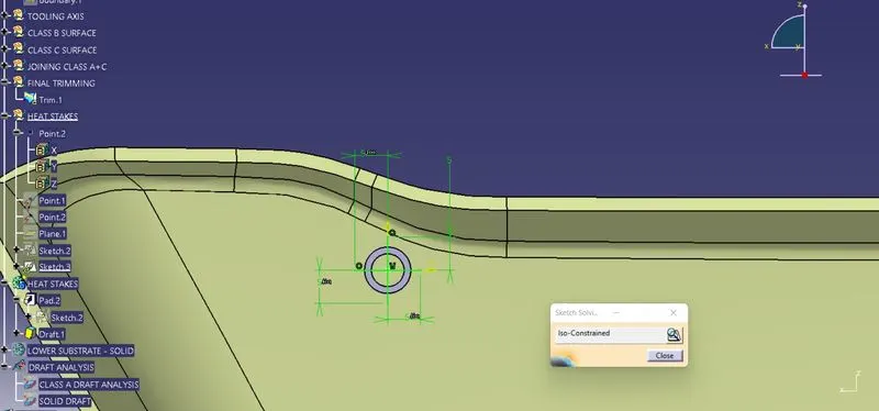
For the Support for the Heat stake Bosses the Supporting Ribs are been added to the screw side faces. For that the supporting Rib sketch are been drawn and by using the pad definition the 2 D sketch are been extruded to the respective lengths.
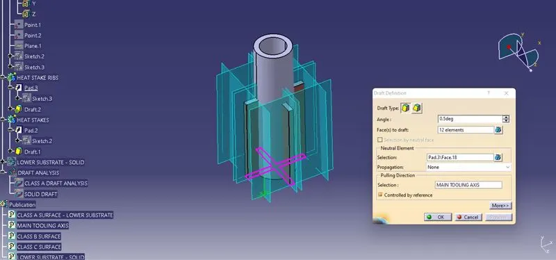
By using the draft definition the faces are been selected to draft and the pulling dircetion are been selected as a Main tooling axis also the neutral element to draft are been selected.
The Boolean operation Union Trim are been performed on the created ribs and the faces to remove are been selected and the Screw Bosses with the supporting Ribs are been formed in the solid part on the Class B surface.
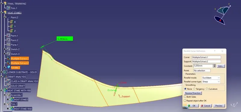
By using the parallel curve definition the edges are been extracted and parallel curves are been created @ the respective distance from the origin curve.
The Heat stakes with the supporting Rib profiles are been selected and using the translate feature the another heat stakes are been created to the respective lengths.
CREATING 4 WAY & 2 WAY LOCATORS ON CLASS "B" SURFACE:
CALCULATION FOR THE RIB DESIGN:
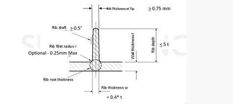
As per the design rules the Locators are been created, The Solid part for the Lower Substrate are been created with the thickness of 2.5 mm.
(1). RIB LENGTH = `5*2.5 mm` ` = 12.5 mm`
(2). RIB THICKNESS = `0.4*2.5 mm``=1.00 mm`
(3). RIB FILLET RADII = `0.25 mm`
(4). RIB DRAFT = `0.5 deg`
(5). RIN THICK @ TIP = `0.75 mm`
By using the positioned sketch the point and plane are been selected and the locator lines are been drawn and the sketches are been Iso - constrained using the repective geometrical and dimensional constraints.
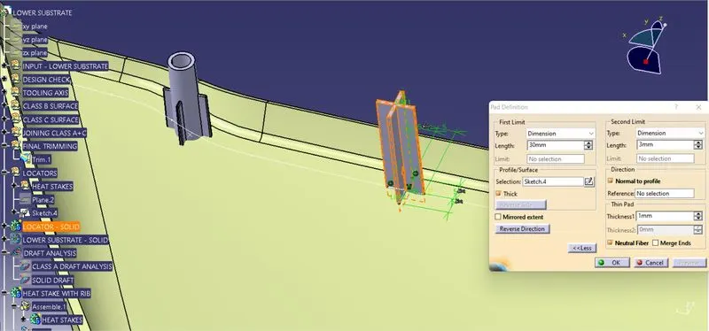
By using the Pad definition the 2 - D sketches are been extruded to the thick and the first and second limit are been defined to the respective lengt to the respective direction.
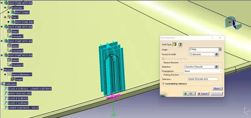
By using the drfat definition the faces are been selected to draft and the pulling dircetion are been selected as a Main tooling axis also the neutral element to draft are been selected.
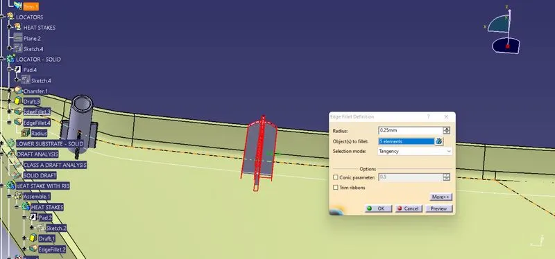
By using the champfer and the edge fillet definition the respective values are provided as per the design rules @ fillet radiiis 0.25 mm and also by using the Boolean opeartion Union Trim the locators are been trimmed by selecting the remove faces and added with the main part body.
CALCULATION FOR THE DOG HOUSE DESIGN:
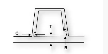
As per the design rules the Dog House are been created, The Solid part for the Door Trim are been created with the thickness of 2.5 mm. For the Door Trim the Calculation are as follows,
(1). PART WALL THICK (T) = `2.5 mm`
(2). Intersection Surface (C) = `0.4*2.5 mm``=1.00 mm`
(3). Height Of B = `3 mm`
(4). OUTER DRAFT = `1.5 deg`
(5). INNER DRAFT = `0.5 deg`
CONSTRUCTION OF DOG HOUSE:
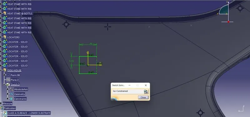
By using the positioned sketch the plane are been selected and by using A Positioned Sketch the line has been created is a sketch that has its origin location or orientation defined with construction geometry. As the construction geometry changes the sketch position or orientation will change accordingly.
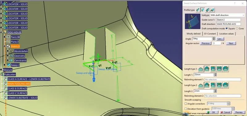
By using the sweep feature the created sketchs are been extruded to the respective length to the respective directions and by using the line the Top surfaces are been closed and Trimmed together with the sweeped surfaces. By using the Thicken feature the created surfaces are been Thickned to 2.5 mm with reference to the master section.
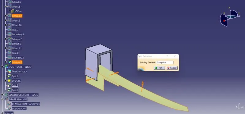
By using the split definition the trimmed surfaces are splitted into the Dog House to form the Intersection @ the Class B Surfaces.
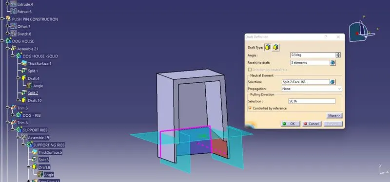
By using the Draft definition the faces to draft are been selected and neutral faces are been selected to draft along the pulling direction as side core Axis.
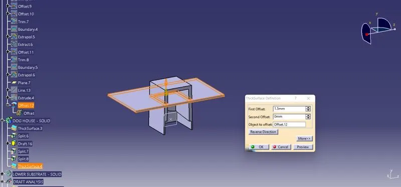
By using the Extracted faces on Top surfaces the surfaces are been offsetted to the respective distances to form the supporting Ribs on the Dog Houses. By using the Thicken feature the surfaces are been Thickned to the respective distance trough the offsets.
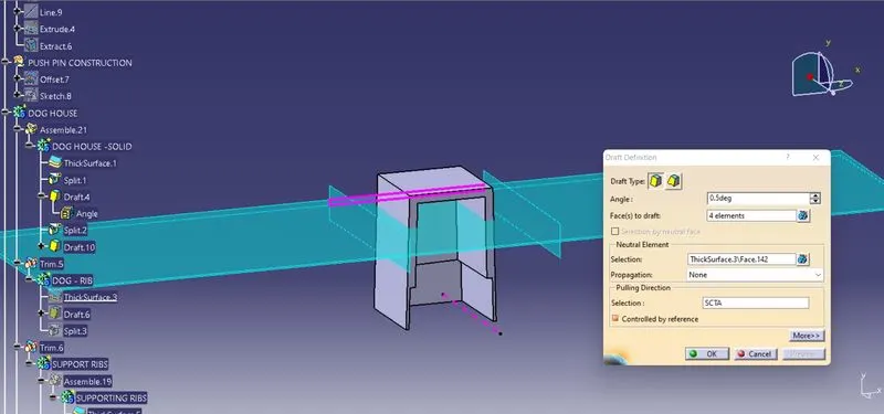
A Draft has been provided on the Created Ribs by using the drfat definition feature @ 0.5 degerees with neutral elements and pulling direction as side core axis.
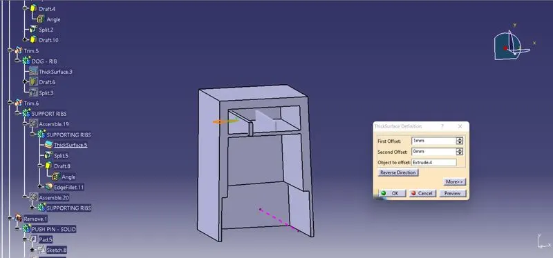
By using the Line, extruded and Union Trim Feature the Supporting ribs on the Dog Houses are been created.
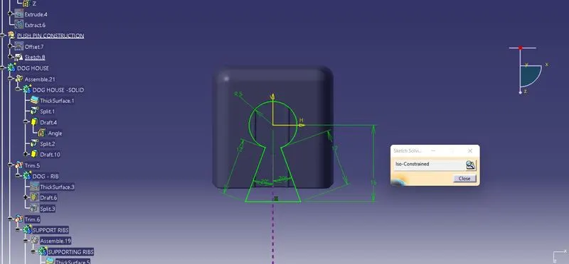
The Push Pin Slot are been sketched using the Positioned sketch and Iso constrained using the Geometrical and Dimensional Constraints.
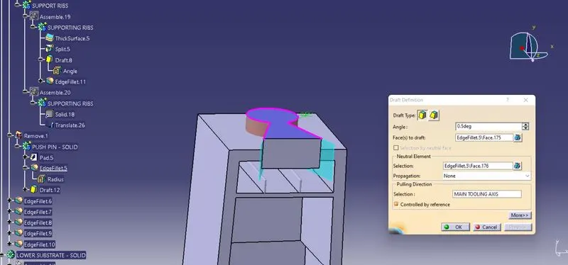
By using the Pad / Pocket features the created 2D sketches are been extruded to the respective directions with required drafts. By using te Boolean Operation Remove feature the extruded pin slots are been pocked on the dog House Top faces.By using the Edge fillet definition the edges are been filleted to the respective values.
DRAFT ANALYSIS:
The Draft Analysis has been performed on the Fianl component created as a closed body using the part design Closed Surface Feature. For Plastic component the Minimum angle required for the daft to be 3 degrees.
The Direction compass are to be selected and placed it on the Main Tooling Axis line and the comass are been locked using the lock feature in te direction.
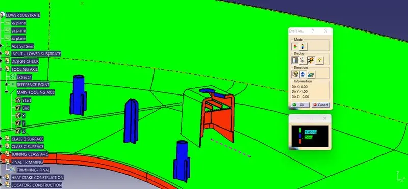
In the Display window the clour code varients are been selected, to know the range of the draft in the Class A surface. In the Display Window the colour varient shows,
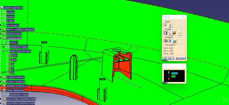
- For 3 degeree - Green Colour Varient (Positive)
- For 0 degeree - Blue colour varient.
- For Negative degeree- Red colour Varient.
By using the Side Core Axis the compass are been placed on the Axis to analyze draft on 0.5 deg on Ribs and suporting faces which are clearing on the side core Tooling Axis.
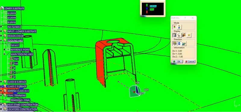
By Using the pointer feature in the Display the draft are been analysed for each individual points. The points perpendicular to the toling axis are displayed as 90 Degeree Direction and the Rib faces are analysed as 0.5 degeree angle.
The drafting are been performed in both the core and cavity side of Class A Surface. The Green colour Implies the draft angle are in the positive region. if The draft angle are been inverted the colour of the surface are implied as Blue colour.
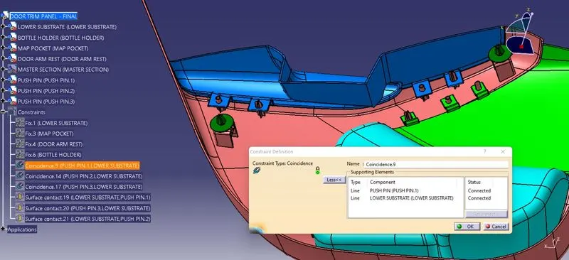
In the Createed Dog House on the Push pin slot the push pin/ clip are mounted uisn the coincide constraint to meet on the respective Dog Houses.
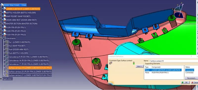
By using the surface contact constraint the faces are been selected to make surface contact on the respective Dog Houses.
CREATING THE FLANGES AND COUNTER PART:
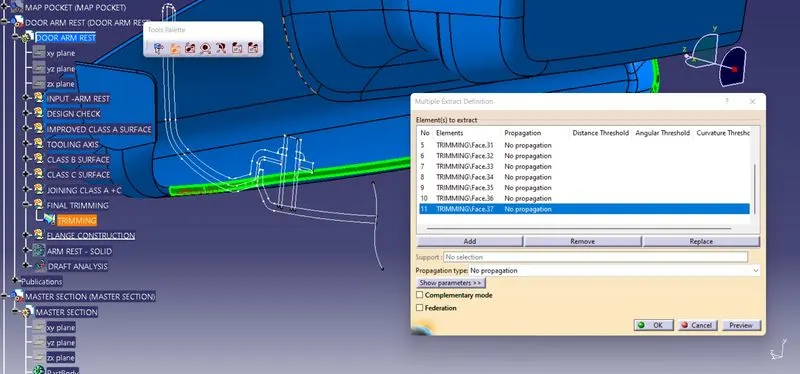
For Creating a Flanges on the Respective parts, Final trimmed surfaces are been selected in which the Class "C" Surfaces are been Selceted by using Multiple Extract feature.
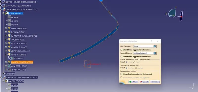
By using the point definition the points are been created between two points in the Heat stake Master section,and by selecting the respective plane through the point the plane are created. By using the Intersection feature the plane and the Extracted Class C surfaces are been selected and intersection are formed.
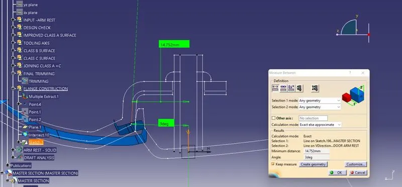
With reference to the Master section The angle from the line of intersection are been measured and created a line as same per Master section.
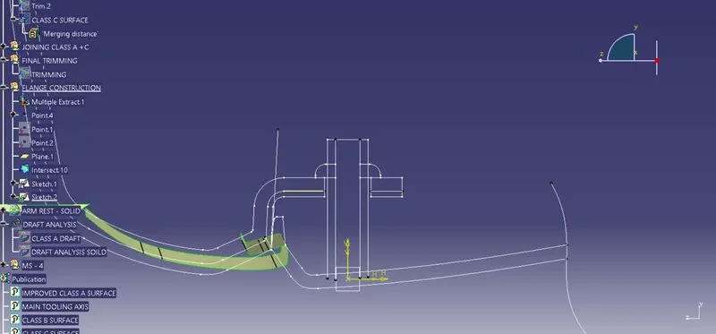
By using the 3 D projection feature the Flat line are been selected and Isolated to break a relationship betwen the Master section and the Parts.
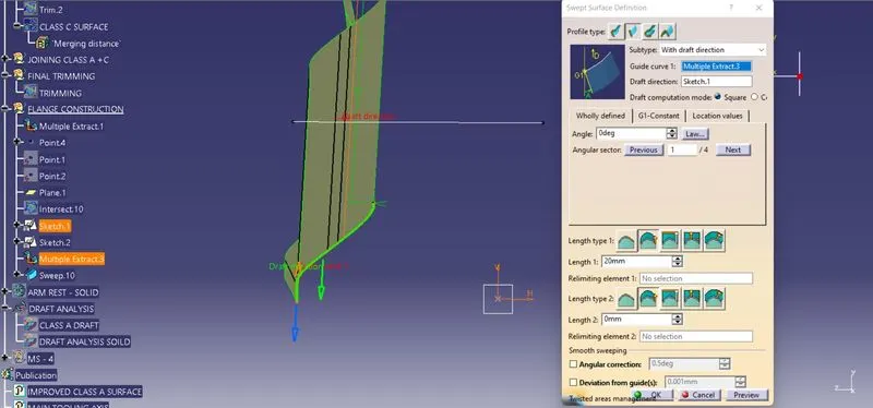
By using the sweep definition the Guide curve and the profiles are been selected to the direction of swwep to the respective lengths.
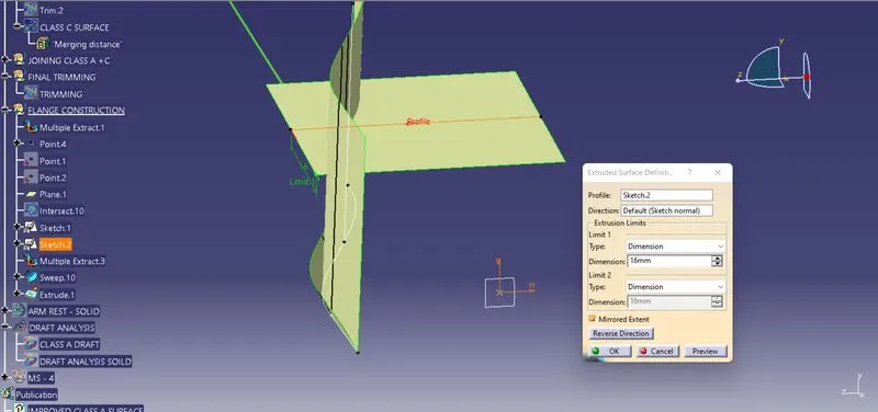
By using the Extrude feature the Flat line are been extruded to the respective direction to the respective length.
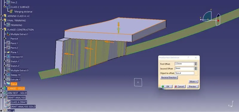
By using the Thicken feature the Trimmed surfaces are been Thickned to the offset of 2.5 mm.
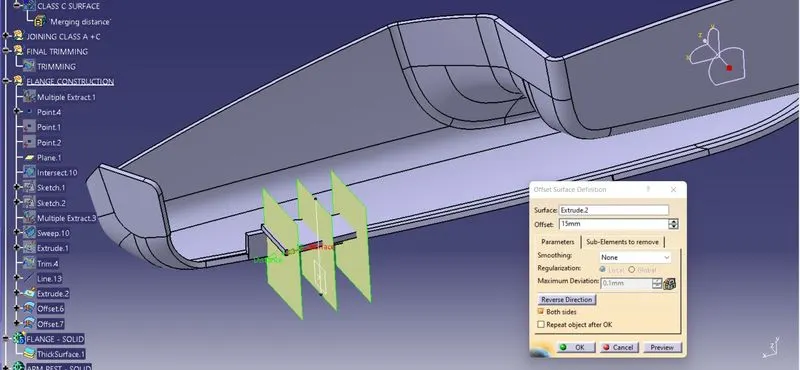
By using the line and extrude feature the surfaces are created perpendicular to the flange and offsetted to the respective lengths on both sides to split and make a flange on Door Arm Rest.
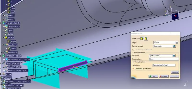
By using the Draft defintion feature the faces to draft are been selected and Neutral element are also selected to create a draft@ 0.5 deg along the pulling direction as side core axis.
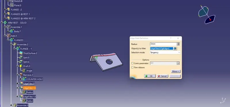
By using te fillet definition feature the Fillets are provided based on the Master section radii measured.
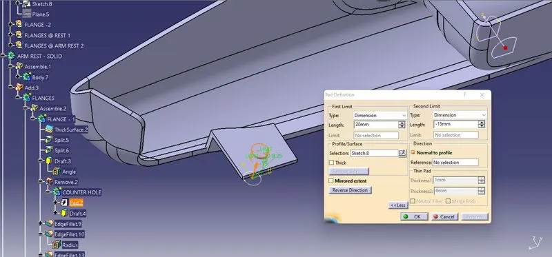
The counter part for the flanges are created by creating a sketch on the flange and by using the pad definition feature the 2D sketch are been paded to the respective length to the respective direction/pocket operation has also been done to make the counter part.
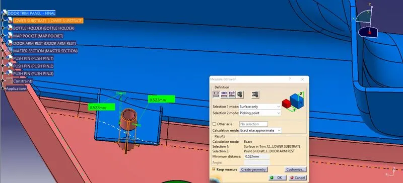
After creating the counter Hole on the flanges the clearence between the counter hole and the Heat stake/locators are based on the design rules @ 0.5 mm clearence.
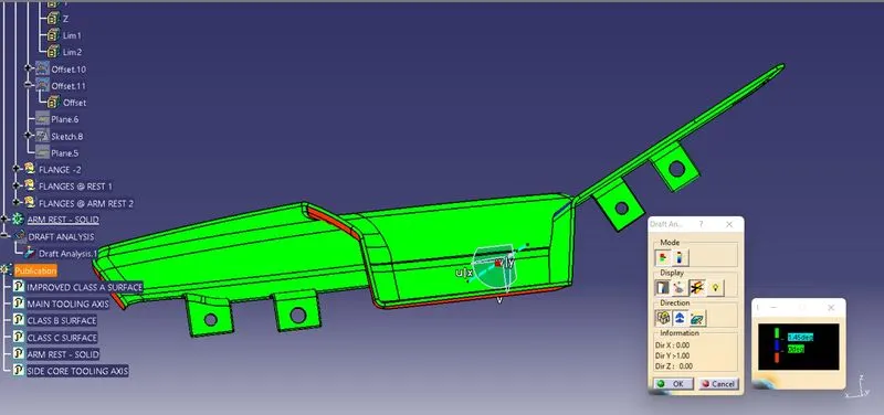
As same as the flanges are been created on the Door Arm rest part and respective counter holes are also provided to fit on the respective Locators and Heat stakes and draft analysis are also performed to clear as per the design rules.
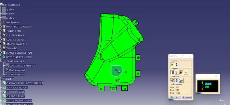
As same as the flanges are been created on the Bottle Holder part and respective counter holes are also provided to fit on the respective Locators and Heat stakes and draft analysis are also performed to clear as per the design rules.
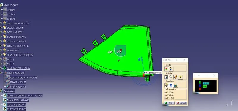
As same as the flanges are been created on the Map Pocket part and respective counter holes are also provided to fit on the respective Locators and Heat stakes and draft analysis are also performed to clear as per the design rules.
PARTING LINE CREATION:
PARTING LINE:
The plastic parting line is to allow the two mold halves to separate so that the molded part can be ejected by the ejector. The position of the parting line flash has a significant impact on the appearance of the molded part and its structural integrity. Unqualified parting lines will result in flash on the product after injection Molding. Secondary operations to remove parting line flash will result in higher labour costs and affect the aesthetics of the product.
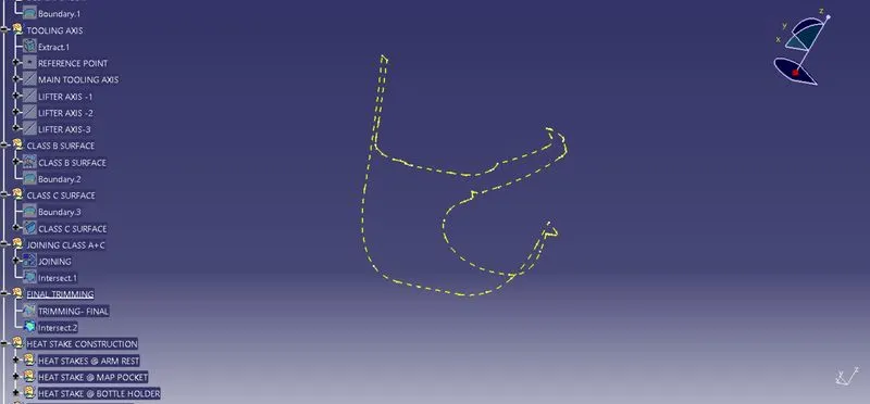
The parting line for the Lower Substarte are created by the intersection of class B surfaces and the Joining of class A and Class C surfaces.
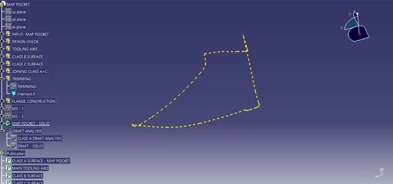
The parting line for the Map Pocket are created by the intersection of class B surfaces and the Joining of class A and Class C surfaces.
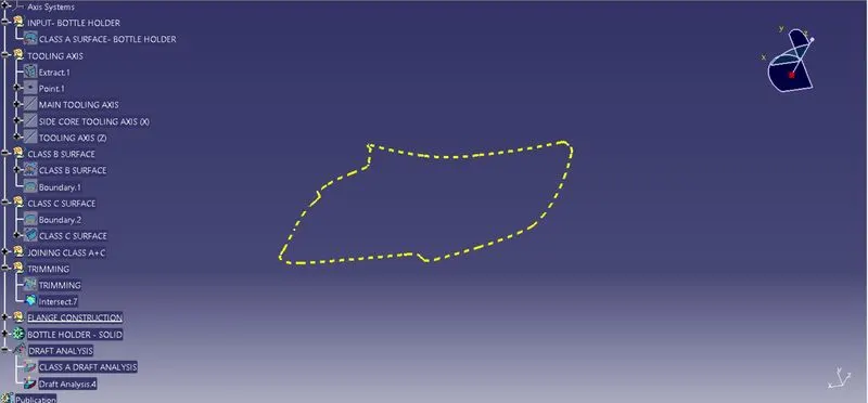
The parting line for the Bottle Holder are created by the intersection of class B surfaces and the Joining of class A and Class C surfaces.
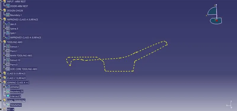
The parting line for the Door Arm Rest are created by the intersection of class B surfaces and the Joining of class A and Class C surfaces.
EXPANDED TREE STRUCTURE:
In CATIA the sketches and the surface operations are been defined using the Geometrical sets. By using the profiles like line, circle, hexagon, polygon, arc the 2 -D sketches are been created with reference to the Geometrical sets. According to the selection of plane from the possitioned sketch the 2-D sketch has drawn with the referene plane.
The surface opeartions like Extrude, extract, trim, split, edge fillets, surface untrim, sweep, smooth curves, extrapolating, Boundary and Fills are deined using te respective geometrical sets.
ASSEMBLY PRODUCT AND ORIENTATIONS:
ISOMETRIC VIEW, FRONT VIEW, SIDE VIEW AND BOTTOM VIEW:
CONCLUSION:
- The Door Trim Panel Plastic Part Component using the Class 'A' surface (Lower Substrate, Map Pocket, Bottle Holder and Door Arm Rest) are Created.
- The Tooling axis and side core axis for a class 'A' Surface, which meeting the requirement of the draft angle are analysed and performed.
- The solid model from the surface are created by using the Closed Surface Feature.
- The Attachement feature 4 - Way Locators, Heat Stakes, Dog House and Flanges on the created Class B Surface are been created as an attachment features.
- The detailed report which explains the Draft analysis and Tooling Axis cration and colour scale varient are explained.
- The Class A, B and C surfaces are Published using the publication option.
- The expanded Tree Structure for the Geometrical Sets are explored .
- The expanded tree structure for part design are explored.
- The 3D part Model with various orientations are attached.