Week 8 - Challenge 4 - Bumper
BUMPER - CLOSED SURFACE FEATURE
AIM:
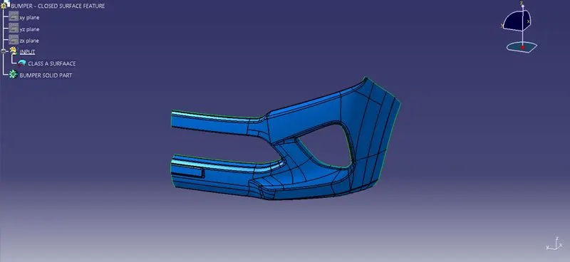
To create a Bumper Plastic Component using a Class 'A' Surface and by using the Closed Surface Feature to create a solid part from the surface.
OBJECTIVE:
- To Create a Plastic Component using the Class 'A' surface.
- To create a Tooling axis for a class 'A' Surface, which meeting the requirement of the draft angle and to analyse the solid model.
- To create a solid model from the surface using the Closed Surface Feature.
- To create a report which explains the Draft analysis and Tooling Axis cration - Bi secting Method and colour scale varient.
- To attach the screenshots of the expanded Tree Structure for the Geometrical Sets .
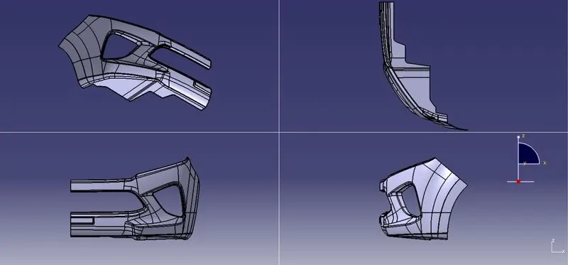
- To attach the screenshots of the 3D Part Model in different orientations.
PUBLICATION:
- Class 'A' Surface.
- Tooling Axis.
- Class 'B' Surface.
- Class 'C' Surface.
- Bumper Solid Part.
INTRODUCTION:
TOOLING DIRECTION:
The Tooling Direction is the direction that the mold pulls apart. The mold is built in two separate pieces,
- A Cavity side and
- The Core side.
The Core pulls apart from the Cavity and that's the Dyeline or the Tooling Direction. The direction in which the mold or core and cavity opens is the tooling axis.
FEATURES OF TOOL:
- Cavity half – The cavity half is the side of a tool that does not move. It is typically attached to the side of the molding machine.
- Core half – The side of the tool that opens and closes with the mold machine against the cavity half. It opens when removing the part from the tool.
- Cooling lines – Channels that allow coolant to flow throughout the tool and control the cooling of the plastic part.
- Ejector system – Pins on the core half of the tool that helps push the cooled part out after molding.
- Runner – A flow path for the plastic resin allowing the press to inject material directly into the part cavity.
- Side actions – Moving pieces within the part cavity added to allow for undercuts.
CATIA 3-D SURFACE SOLID PART MODEL - CLOSED SURFACE FEATURE
CLASS 'A' SURFACE:
DESIGN CHECK:
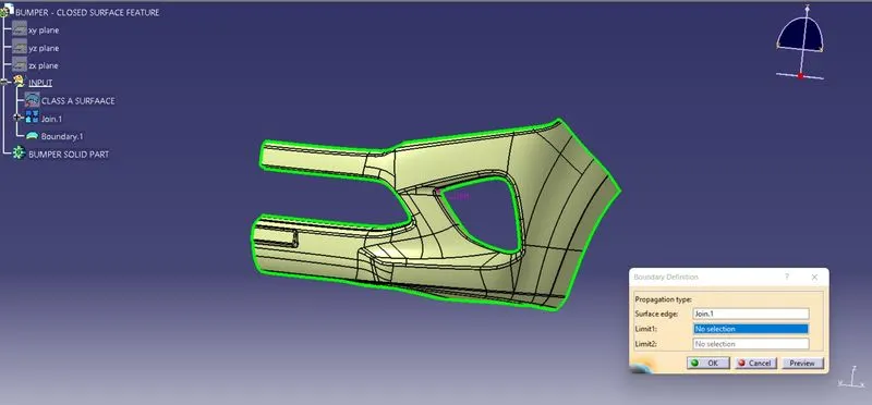
The Class A Surface are Checked Visually by using the Join Feature or by using the boundary feature the Class A surface are selceted and Disassembled the Surface to check the surface are created without the gaps.
The Class A Surface should be created without the boundary Gaps. By using the Join Definition with the Merging distance of 0.001 mm the Class A surface are Joined Together to check the connectivity.
PUBLISHING THE CLASS A SURFACE:
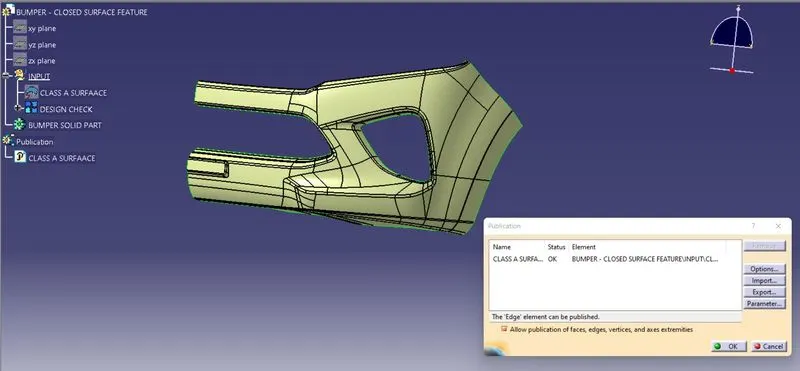
By using the Publication option the Class A Surface are Published. The Publication is used to retrive the Class A surface in the easier way to use from the Structured Tree Implementation.
CREATING TOOLING AXIS:
The Tooling for the Class A Surface are Created in the direction in which the parts are getting Ejected from the Tool. The Tooling Axis which defines the core and cavity pulls apart from the Tooling Direction.
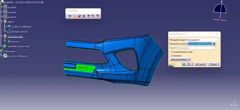
By uisng the EXtract feature definition the flat surface are selected and extracted wit the propogation type as No propogation.
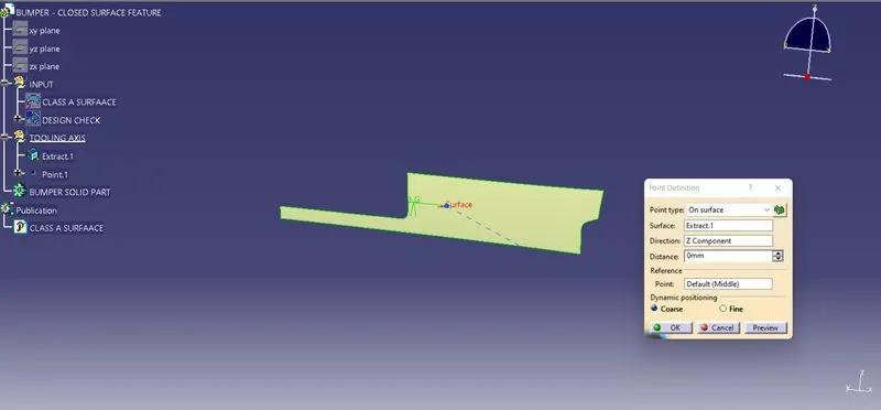
By using the Point Definition, The point has been created on the surface midpoint by selecting the point type as On Surface.
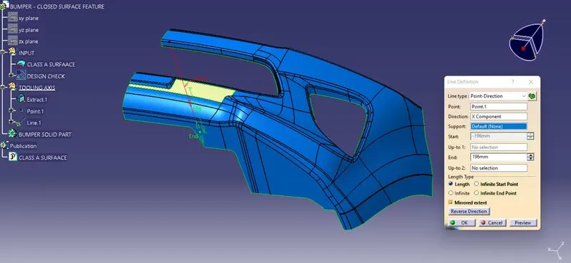
The Tooling Axis has been created using the line definition feature. From the line type point direction, Point has been selected and direction along x component are selected to define the line.
MATERIAL MODES:
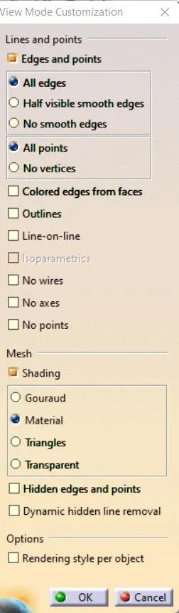
For the Draft Analysis, the material modes are Selected from the Shading Type.
DRAFT ANAYSIS:
For a Class A Surface, The Draft analysis are to be performed in order to meeting te requirement of the draft angle to the required Tooling Axis. For Plastic component the Minimum angle required for the daft to be 3 degrees.
The Direction compass are to be selected and placed it on the Main Tooling Axis line and the comass are been locked using the lock feature in te direction.
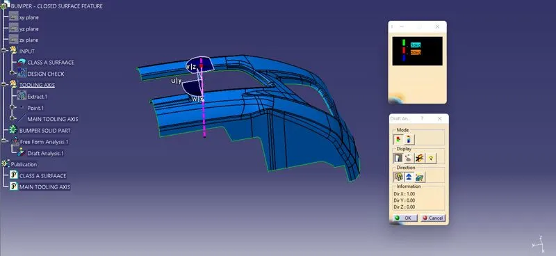
In the Display window the clour code varients are been selected, to know the range of the draft in the Class A surface. In the Display Window the colour varient shows,
- For 3 degeree - Green Colour Varient (Positive)
- For 0 degeree - Red colour varient.
- For Negative degeree- Blue colour Varient.
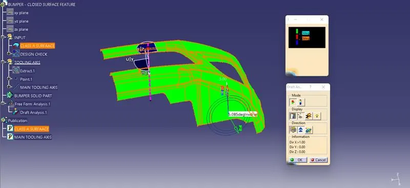
By Using the pointer feature in the Display the draft are been analysed for each individual points. The points perpendicular to the toling axis are displayed as 90 Degeree Direction and the Rib faces are analysed as 5.085 degeree angle.
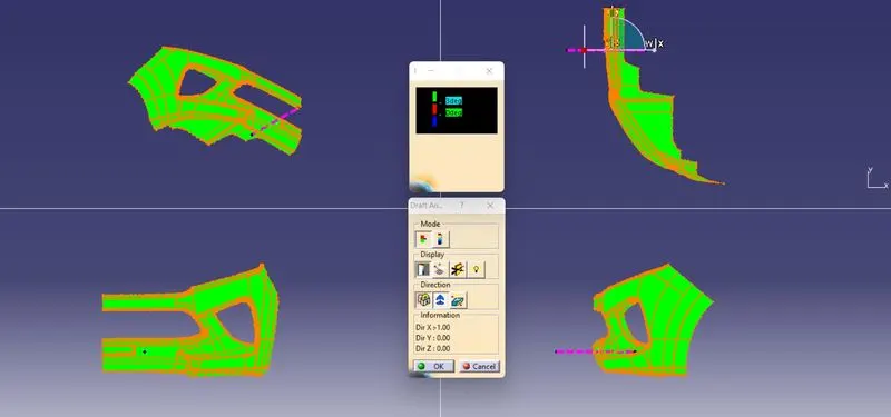
The drafting are been performed in both the core and cavity side of Class A Surface. The Green colour Implies the draft angle are in the positive region. if The draft angle are been inverted the colour of the surface are imled as Blue colour.
CREATION OF CLASS 'B' SURFACE:
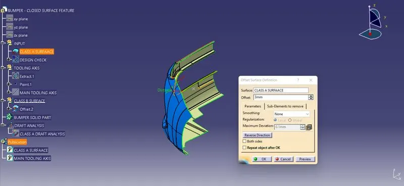
By using the Class A Surface the Class B Surface are created by offsetting to the respective length to the respective direction. By using the offset surface definition the class A Surface are been offsetted to the length of 3 mm from the direction towards downward.
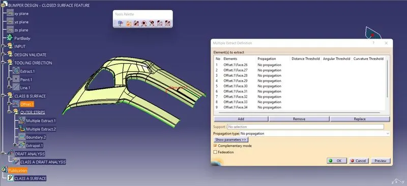
By using the Multiple extract definition, in the complementary modes the areas t be removed are been seleceted. By using the complementry mode in the Multiple extract definition the Sub - elements the patial fillets and the areas are been removed.
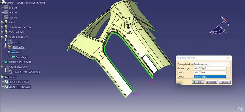
By using the Boundary feature the outer strip are been selected in order to extraploate the surfaces.
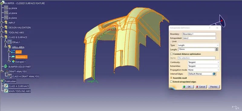
By using the Extrapolate feature the boundary surfaces are been extrapolated by selcting the boundaries and also the extrpolands. The continuty for the extrapolation are selected as curvature and propogation mode are been selected as point continuity. By selecting the features the boundaries are been extrapolated to the respective length provided.
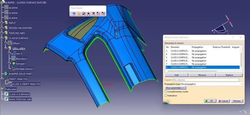
By using the Multiple Extract feature the elements are been selected from the class A Surface, using Multiple extract and offseted to the respective direction @ 3 mm.
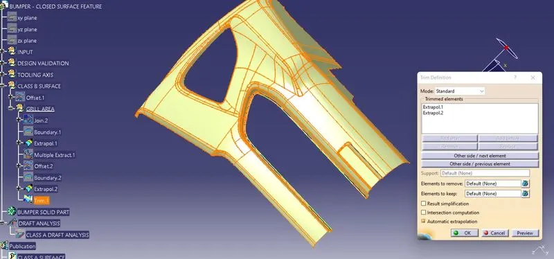
By using the Trim definition feature the extrapolated surfaces are been selected and trimmed with each other to form the surface as Class A Surfaces.
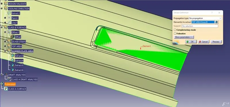
By using the extract definition surfaces are selected in the Number plate area to form the class B surface from the class A Surface.
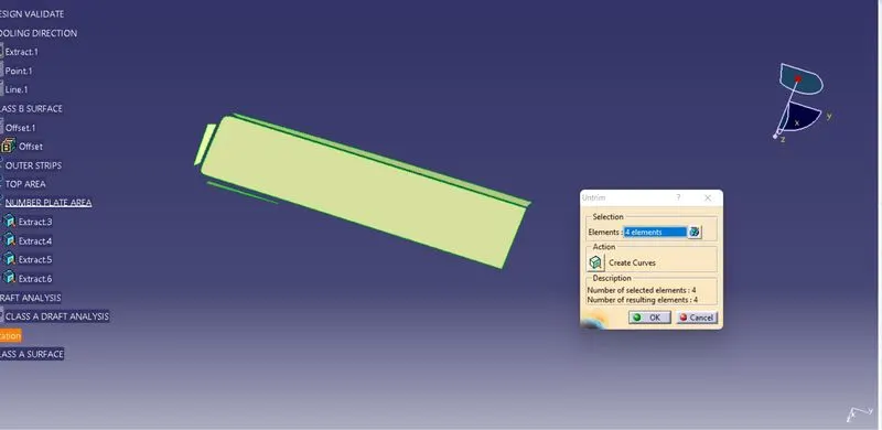
By using the untrim definition the extracted surfaces are been untrimmed using the untrim definition.
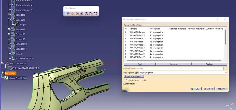
By using the Multiple extract definition, in the complementary modes the areas t be removed are been seleceted. By using the complementry mode in the Multiple extract definition the Sub - elements the patial fillets and the areas are been removed.
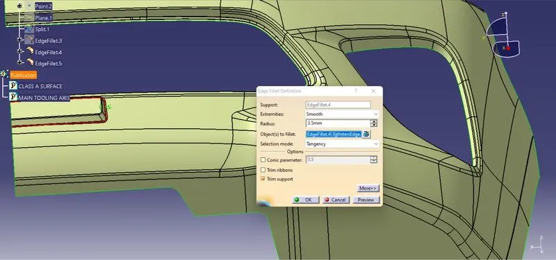
By uisng the edge fillet definition the edges are been selected and filets are been performed on the edge surfaces.
CREATING CLASS 'C' SURFACE:
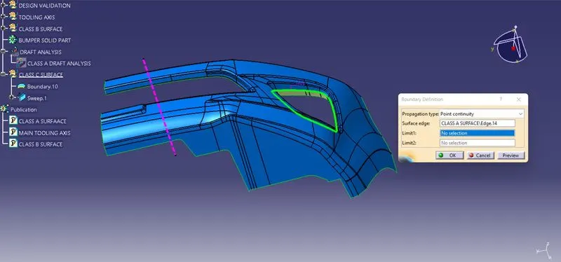
To make the Class C Surface, the Boundaries are been Extracted from the Class A Surface. The Lightning area Boundary, are been extracted using the Bundary feature/ EXtract definitions.

By using the Sweep surface Creation definition, The respective profile type are been selected and subtype with draft direction are been selected. In that the Guide curve are selected as the. Boundary in the Class A Surface, and draft direction are selected as Tooling Direction with the draft angle of 3 degree are perforemed and the creation of Class C Surface.
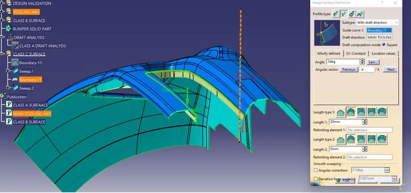
By using the Sweep surface Creation definition, The respective profile type are been selected and subtype with draft direction are been selected. In that the Guide curve are selected as the. Boundary in the Class A Surface, and draft direction are selected as Tooling Direction with the draft angle of 3 degree are perforemed and the creation of Class C Surface.
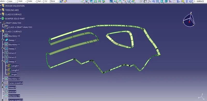
The Class C Surfaces are been created by using the sweep feature and also the Direction along the Tooling direction and the reference with the surface and guide curve are been selected to form the Class C Surfaces.
JOINING CLASS A AND CLASS C:
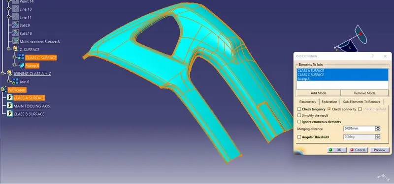
By using the Join feature the Class A and Class C Surface are Joined Together with the Merging Distance of 0.001 mm.
FINAL TRIMMING:
The Final Trimming Has been performed on the Class B and Joined Class A and C surfaces. The Trimming has been performed.
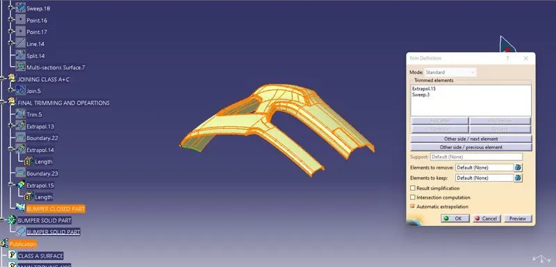
CLOSED SURFACE:
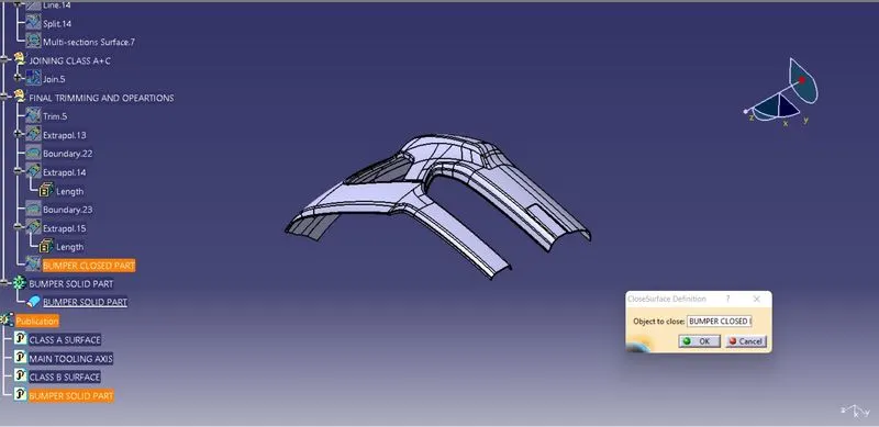
By using the close surface definition the part surface are selected to make them into solid part from the part workbench.
DRAFT ANALYSIS:
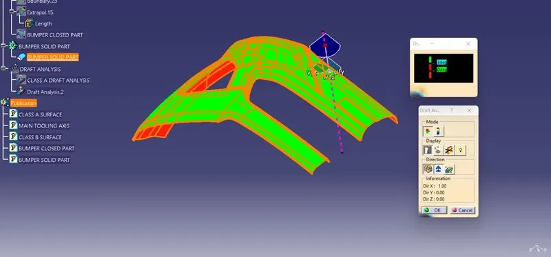
The Draft Analysis has been performed on the Fianl component created as a closed body using the part design Closed Surface Feature. For Plastic component the Minimum angle required for the daft to be 3 degrees.
The Direction compass are to be selected and placed it on the Main Tooling Axis line and the comass are been locked using the lock feature in the direction.
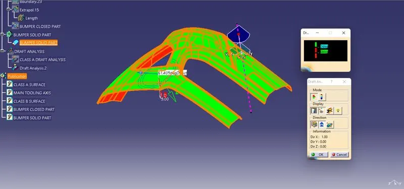
In the Display window the clour code varients are been selected, to know the range of the draft in the Class A surface. In the Display Window the colour varient shows,
- For 3 degeree - Green Colour Varient (Positive)
- For 0 degeree - Red colour varient.
- For Negative degeree- Blue colour Varient.
By Using the pointer feature in the Display the draft are been analysed for each individual points. The points perpendicular to the toling axis are displayed as 90 Degeree Direction and the Rib faces are analysed as 61.409 degeree angle.
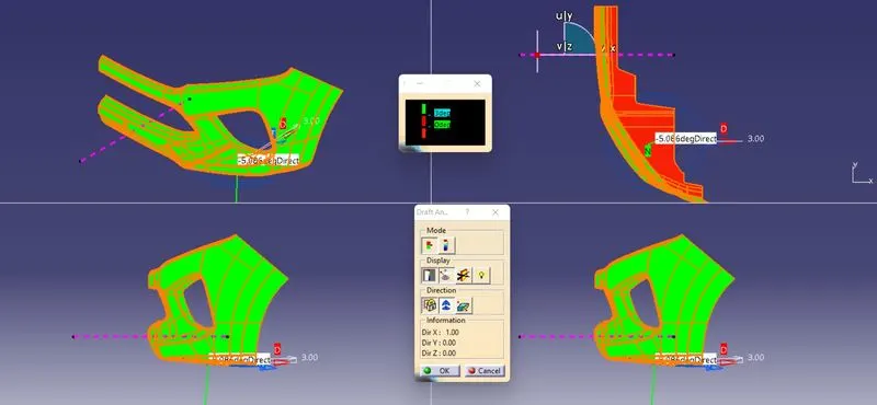
The drafting are been performed in both the core and cavity side of Class A Surface. The Green colour Implies the draft angle are in the positive region. if The draft angle are been inverted the colour of the surface are imled as Blue colour.
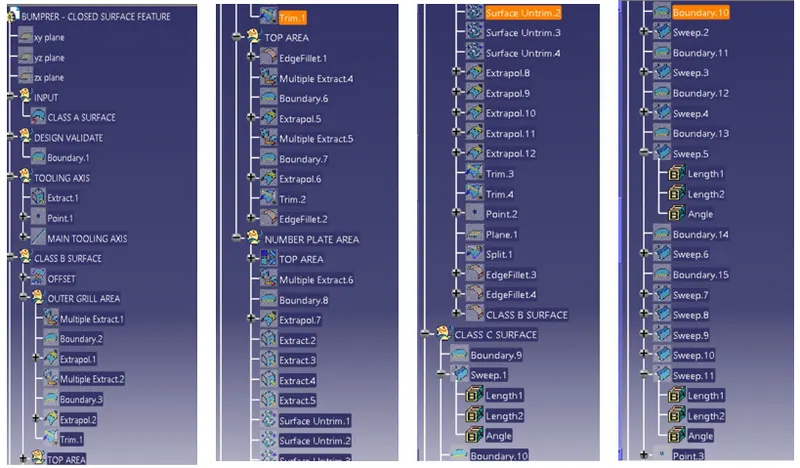
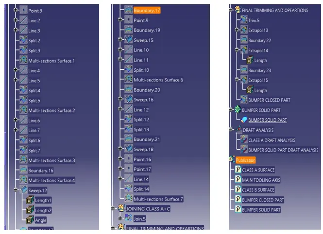
EXPANDED TREE STRUCTURE:
In CATIA the sketches and te surface operations are been defined using the Geometrical sets. By using the profiles like line, circle, hexagon, polygon, arc the 2 -D sketches are been created with reference to the Geometrical sets. According to the selection of plane from the possitioned sketch the 2-D sketch has drawn with the referene plane.
The surface opeartions like Extrude, extract, trim, split, edge fillets, surface untrim, sweep, smooth curves, extrapolating, Boundary and Fills are deined using te respective geometrical sets.
PUBLICATIONS:
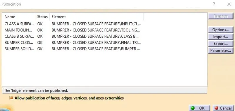
The Class A,B,C and the main Tooling Axis are been publised using the publication option. The Bumper solid part are also published usin publication option.
3 DIMENSION PART AND ORIENTATIONS:
ISOMETRIC VIEW, FRONT VIEW, SIDE VIEW AND BOTTOM VIEW:
CONCLUSION:
- The Bumper Plastic Part Component using the Class 'A' surface are Created.
- The Tooling axis for a class 'A' Surface, which meeting the requirement of the draft angle are analysed and perfrmed.
- The solid model from the surface are created by using the Closed Surface Feature.
- The detailed report which explains the Draft analysis and Tooling Axis cration and colour scale varient are explained.
- The Class A, B and C surfaces are Published using the publication option.
- The expanded Tree Structure for the Geometrical Sets are explored .
- The expanded tree structure for part design are explored.
- The 3D part Model with various orientations are attached.