Hood design-Week 2
HOOD ASSEMBLY DESIGN
AIM:
To design a Hood assemly, Body In White (BIW) component from a Outer Panel, Striker and Hinge Models provided, by considering the Master section for the Nominal Thickness of a component for the creation of Inner Panel.
OBJECTIVE:
- To Create a BIW Component of Hood Panel Assembly using the Inputs Provided.
- To Design Hood Outer Panel, Inner Panel and the necessary reinforcements by considering the Master Sections.
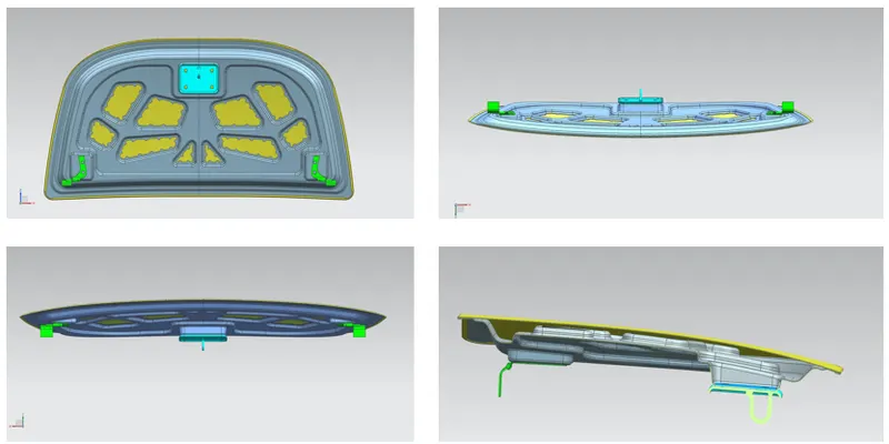
- To create an Assembly of Hood Inner Panel, Outer Panel, Latch, Hinge and the Reinforcements.
- To create a detailed report about the Hood Design by explanation about hood and its components, Latch Trajectory, Mastic Data, Emboss Definitions.
- To Explain about the Manufacturing process, Deep-Drawing, Hemming.
HOOD THICKNESS:
- Outer Panel Thickness `= 0.75mm`
- Inner Panel Thickness `= 0.75mm`
- Reinforcement Thickness `= 1.5mm`
INTRODUCTION:
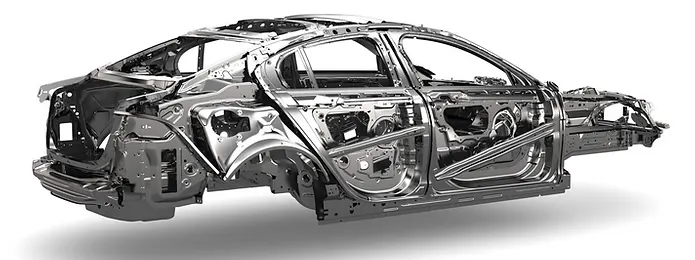
BODY IN WHITE (BIW):
In the Automotive Industry BIW (Body in White) is the common terminology used to mention the car sheet metal welded structure (body shell). Sub-assemblies like Under body, Body side Left Hand Side/ Right Hand Side, Front End, Roof etc. gets welded together by various metal joining process like resistance spot welding, Laser welding, MIG welding to make welded metal shell (Without Door, Trunk-lid / Tailgate) , Fender, Hood) called Body in White. Automotive car shell made before painting is called Body in White.
HOOD:
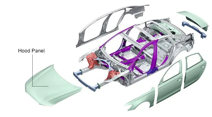
Hood is a main component of front portion of a car, hinged cover that rests over the engine bay of a front-engine vehicle. It is an opening body panel that covers the engine in front engine vehicle. It consist of an outer panel and inner panel. The inner panel provides the strength while the outer panel functions as the metal cover. It is an access panel to the engine compartment to enable maintenance of power train, drive belts, battery, fluid levels and lamp units.
DESIGN CONSIDERATIONS FOR HOOD:
HOOD OPENING ANGLE:
Hood opening angle is different for different regions/countries. It is decided by the average height of the human in that particular country. Head clearance zone is the clearance such that when the hood is in fully open condition it does not hurt the head of the person that is standing next to the hood .This is controlled by the opening angle of the hood .Some region may have people with average height of 5.5 feet and another region may have people with average height of 6 feet .
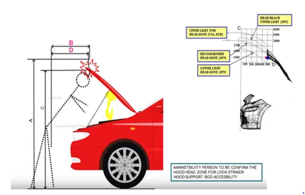
The human comfort factor for automobile design is first consideration. It is a method to safeguard and protect space for the human user and necessary components that make up the vehicle being designed. All safety regulations are ensured during this process.So deciding the right opening angle for the hood is an important criteria.
HOOD STAY:
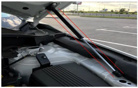
A hood stay is an device which is used to keep the hood in an open position. There are two types of hood stays,
(1). SUPPORT ROD
(2). GAS STAY
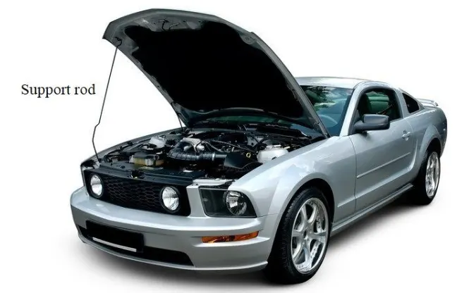
(1). SUPPORT ROD:
Support Rod is a simple metallic rod. It is not usually made linear to increase rigidity of rod but the length from line connecting support rod retaining point with retain point on body side to maximum bending point should be less than 35mm to ensure the strength of support rod. It should have sufficient clearance with other engine components to avoid rattling noise.
(2). GAS STAY:
Gas Stay is a device used for supporting the engine hood of a vehicle in its open position by means of an actuator which is activated by gas. In case of gas stay only initial force is required to open the hood then it automatically opens at desired angle with the extension of pneumatic piston in cylinder of gas stay assembly.
PEDASTRIAN SAFETY:
The most important safety requirement is regarding the frontal collision. It should withstand in high collision forces as well as it should divert the forces in outward direction so intensity of collision forces would be reduced to cabin side of car.
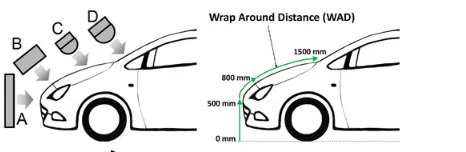
The head impact test assessment results mainly depend on the hood structure, whereas the leg impact tests results are highly influenced by components adjacent to the hood. Because the focus of these communications is on the hood design concept, the results presented in this study are limited to the head impact test results.
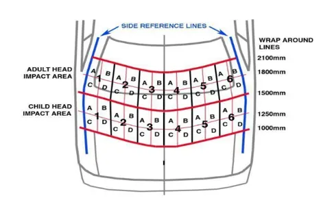
Wrap around Distance (WAD):- It is the geometrically traced distance from the contact point with the Ground Reference Plane, vertically below the front face of the bumper, to any point on the vehicle front structure.
Besides functioning as an engine compartment cover, the hood of modern vehicles can also help manage the impact energy of a pedestrian’s head in a vehicle-pedestrian impact. However, a hood’s ability to absorb impact energy may be impeded by the proximity of the hood to components packaged inside the engine compartment, i.e., by its under hood clearance.
MANUFACTURING PROCESSES:
The most important design consideration of any component is manufacturing aspect. In sheet metal, the component is manufactured by press tool dies. The Press tool is stamping which includes cutting operations like shearing, piercing etc. and forming operations like bending, Deep drawing, hemming etc.
DEEP DRAWING:
The deep drawing is used to manufacture a product with seamless, complex shapes. This is tool related manufacturing process where the metal is stretched or extended between two tool halves to create prospective shape.
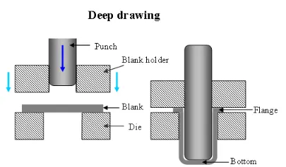
The process involves a punch with a round comer and a die with a large radius. The punch-die clearance is slightly larger than the thickness of the sheet metal to be deep drawn. As the load applied through the punch, the sheet metal is forced to flow radially and sink into the die cavity to form a cup. The process is best suitable for complex shaped problems. Deep drawing is one of the most widely used processes in sheet metal forming. Apart from its use in many other sectors, it is applied in the automotive industry for the manufacturing of car body parts.
BLANKING AND PIERCING:
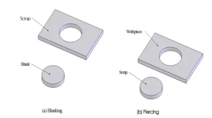
Blanking and piercing are the shearing processes in which a punch and die are used to produce parts from coil or sheet stock. The blanking produces the outside features of the component, while piercing produces internal holes or shapes.
EMBOSSING:
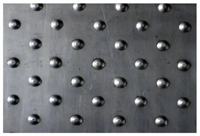
Sheet metal embossing is a stamping process for producing raised or sunken designs or relief in sheet metal. This process can be made by means of matched male and female roller dies, or by passing sheet or a strip of metal between rolls of the desired pattern.
HEMMING PROCESS:
Hemming is the technology used in the automotive industry to join inner and outer closure panels together. It is the process of bending/folding the flange of the outer panel over the inner one. The accuracy of the operation affects significantly the appearance of the car's outer surfaces, and is therefore a critical factor in the final quality of a finished vehicle. Hemming is performed in order to achieve a better final geometry in the vehicle's part and add resistance and rigidity to the part. Also, to allow a safe handling of the part.
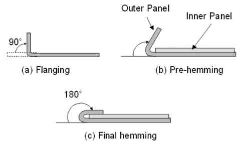
The panels which are visible outside are joined with the inner panels or supports with the help of the hemming process. Hemming is comes into for outer panels because thermal joining processes leave the residual marks which are acceptable on the aesthetic surfaces.
ROLL HEMMING:
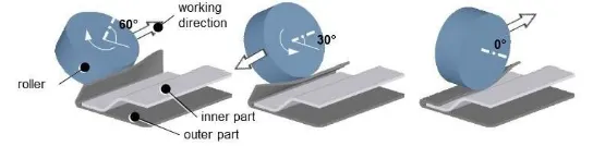
Roll hemming is carried out incrementally with a hemming roller. Roll hemming is very flexible to use and tool costs are significantly lower as compared to those of conventional die hemming. However, the cycle times are much higher since the hemming is realized using a hemming roller which follows a defined path. Roll hemming operation can also be divided into several pre-hemming and final hemming process steps.
COMPONENTS IN HOOD ASSEMBLY:
- Hood Outer Panel
- Hood Inner Panel
- Stricker
- Hinge
- Latch & Reinforcements
HOOD OUTER PANEL:
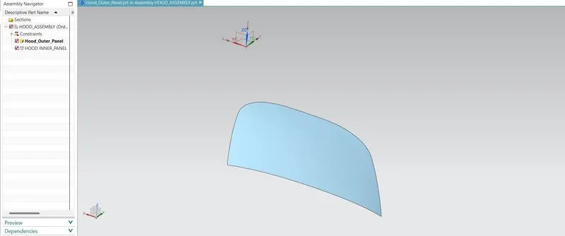
The outer panel has the aesthetic look to it but on its own is very weak and not capable of handling force during impact.The Hood Assembly is created inwhic the Skin data for the outer panel are been imported to create a Hood design as per the requirement.
HOOD INNER PANEL:
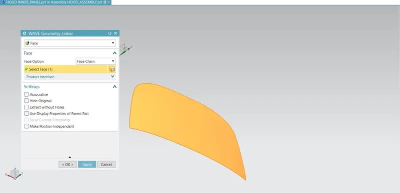
By using the wae geometry linker the Inner panel are been craeted in the Assembly of hood in which the faces of the outer pannel are been selected to create the ood inner panels.
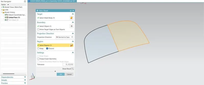
By using the trim sheet command the Inner panel are been spitted into the cross section by halves through which the Inner pannels are been offeseted as per the master section.
MASTER SECTION:
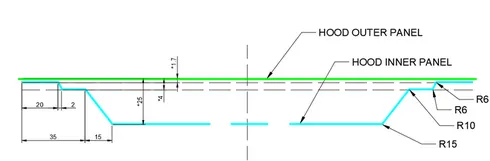
By Reference to the Master section the Inner pannel splited sheet are offsetted to the respective distance and Radius are provided accordingly.
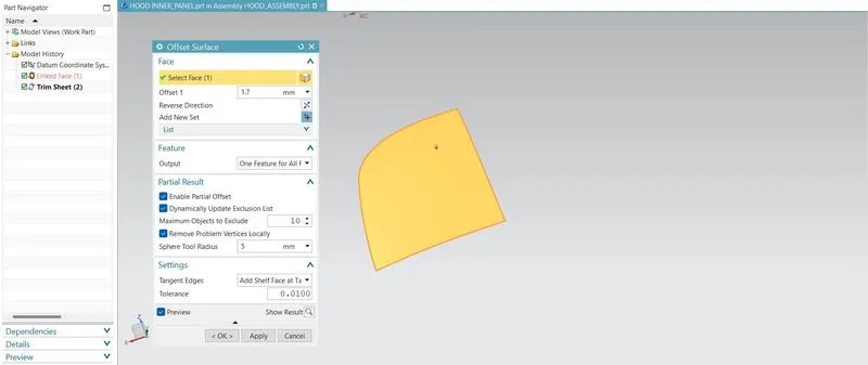
By using the offset command the Inner pannel are been offsetted to the respective distance @ 1.7 mm downward.
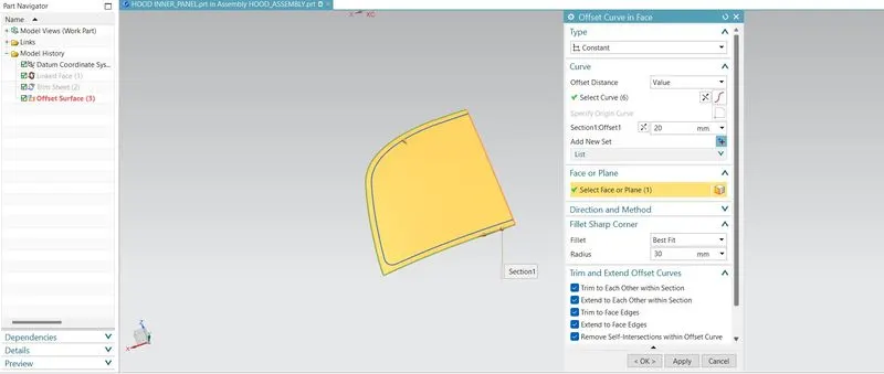
The face on curve aommand are used to select the edge faces of the ofsetted sheet to make the First flages as per the Master section provided and created.
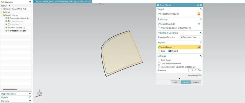
By usin the Trim sheet command the faces to be target are been selected and bouindary sre selected to trimm the sheet from the respective region. All the flages are created and offseted asper the master section.
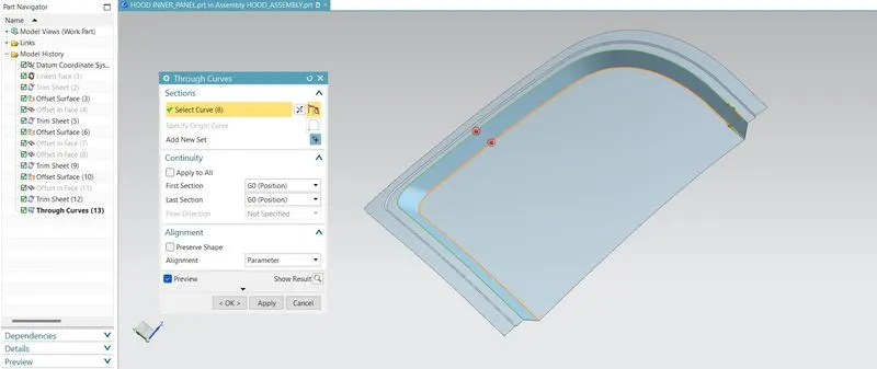
The through curve command are used to create a surfaces connecting the two edges of the sheet.
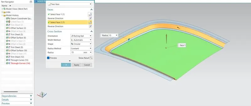
The edges of the created sheets are been filleted as per the Master section to create a fillet on the two faces by selectin each faces filets are been created.
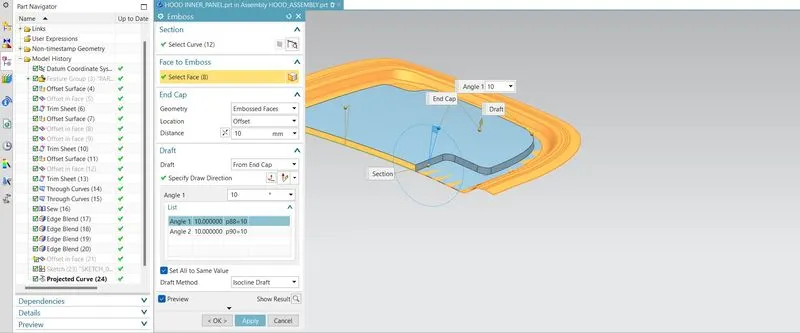
By using the sketch feature the 2 -D sketches are been drawn and projected on the surface to create Embossing on the Surface offsetted at the respective length.
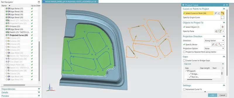
The second layer of the Sketches are been drawn and projected onto the sheet embossed to create the 2 nd layer Emboss on the surface @ respective length.
MASTIC DATA'S:
Mastic sealants used between the outer and inner panel. Mastic sealants are the rubber like elastic compound which connects the outer and inner panels of car hood at specified points. Mastic sealants are used in the region between the inner and outer panel because other joining process like welding or riveting are not good for car aesthetic design. It also helps in improving NVH (Noise, vibration, and harshness) characteristics.
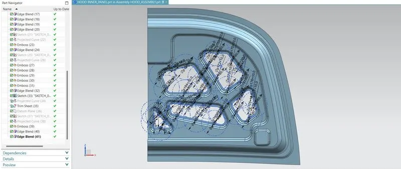
After the creation of the Emboss on the Surface the seets are been trimmed based on the boundary and region are selected to trimm off the sheets. The Masteic data points are creted on the Trimmed off sheets. Mastic sealant points are effective around a circular region of 80mm diameter.
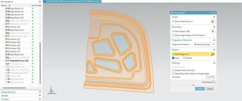
By uisng the trimm sheet command the Mastic data are been created in the Inner panel of the Hood surface. The created mastic sealents are between the inner and outer pannle joining @ between 5 mm distance.
HINGE EMBOSS CREATETION:
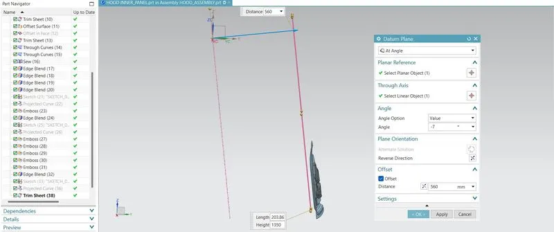
By using the datum plane command the datum plane are been created @ an angle @ Negative angle of -7 deg. and offseteed at the certain distance to craete a parallel plane on the dataums.
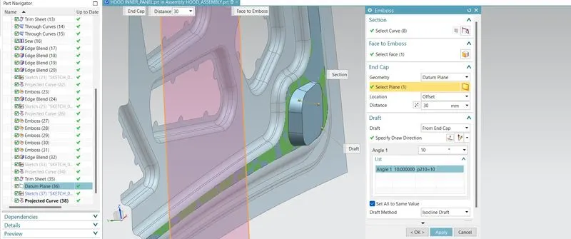
With respect to the datum plane the Hinge embosses are been created and offsetted to the respective distance to craete the Hinges on the Inner panel and uismg the edge blend feature the facses are been filleted @ respective fillet radii.
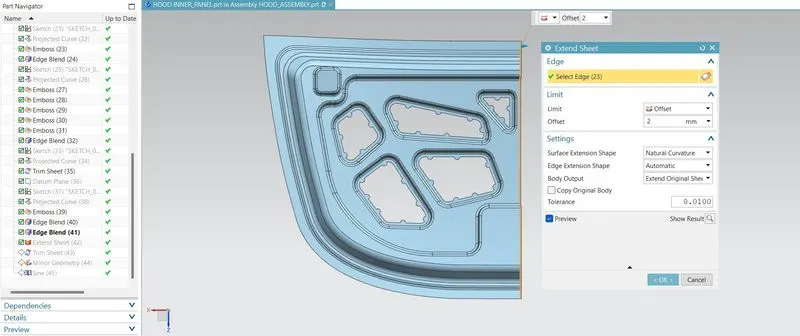
By using the Extenf sheet command the sheets are been extended to the Minimum distance and trimmed to the respective plane accordingly.
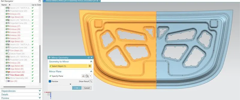
After Trimming the Sheets, by using the Mirror Geometry command the seets are been Miirorsuing the Plane definition repsctively.
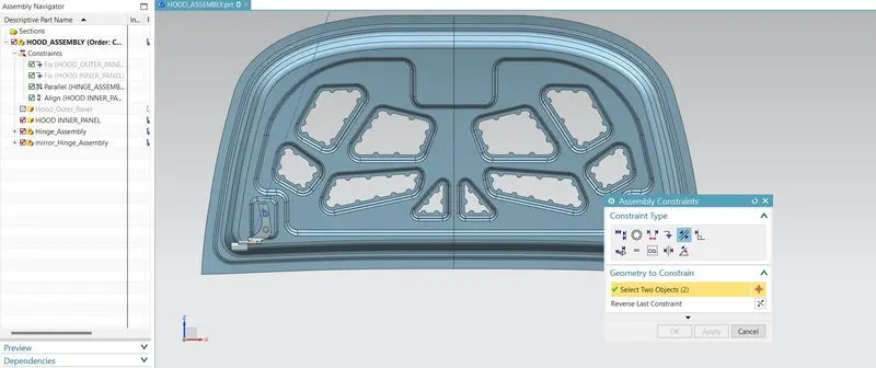
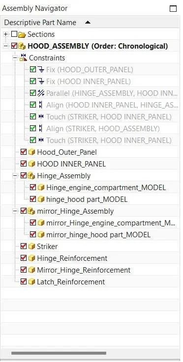
In the Assembly, the repective constraints are been provided to fix te Hinges on the axis to rotate in the Inner panel. The Touch and Align constraints are been used to Fix the inge assembly on the Inner panel.
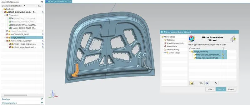
By using the Mirror assembly command the inges are been Mirrored with respect to the plane definition.
CREATING LATCH TRAJECTORY:
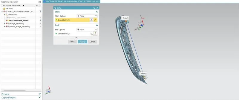
With the Hinge axis the Inner panel are rotaed along the axis og the Hinges provided. The points are created on the Hinges and line are been created between the two points throug whic the latch are rotated.
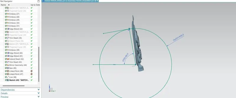
By using the angular constarints te tangential line has been drawn thriug whic the stricker are been move dalong the hinge axis of rotation.
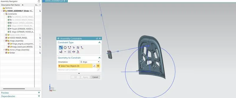
The Align constraint are bben provided onto the stricker and the Inner panel created and Touch constraint are been provided to create the relationship between the Inner panel to the Stricker created.
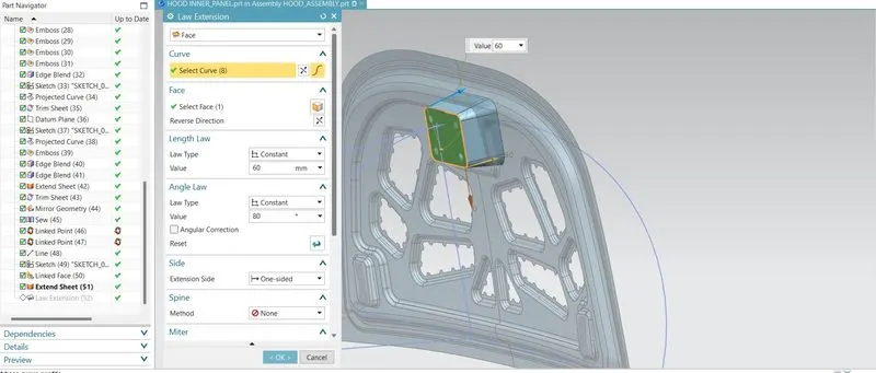
By uisng the Law extension the stricker faces are been extended and using the trim and extend command the faces are been trimmed off and @ the respective draft angle.

By using the Ticken command the Inner and Outer pannel are been Tickened as per the requirements @ 0.75 mm to the respective direction.
REINFORCEMENT ON HINGE AND STRICKER:
Reinforcement are provided mainly in hinge and latch region. When hinge and latch assemblies are attached to inner panel, strength of that area reduces locally so we add some additional material to increase the strength of the area locally. Thickness of reinforcement material is provided according to the design requirements. In this project, 1.5mm thickness has been given to both latch and hinge reinforcement.
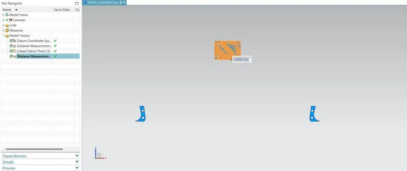
Based on the Design Requirement the inge and the Latch Reinforcements are been created at the thickness of 1.5 mm.
HEMMIMG:
DESIGN DATA:
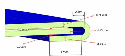
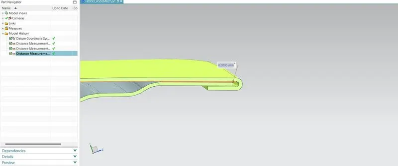
Based on the Design requirement, The hemming processes has been done on the Inner and Outer panel and gap between the Ineer and Outer panel are created @ 0.2 mm.
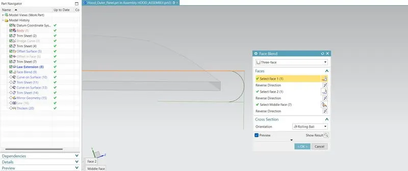
The Outer panel Sheet are been offseteed to the distance of 2.65mm downward and by using the Law extension the offsetted faces are been extended to the distance perpendicular to the Outer panel surface. By using the Three face blend the faces are been selected and created a Hemming to join the outer and inner panels.
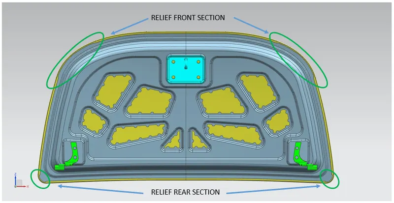
FRONT AND REAR RELIEF:
A bend relief prevents tears from occurring where there is a transition between bends or between a bend and a flat surface. They are a great way to ensure a clean looking part that is free from deformation, burrs, and sharp points where the bend edges terminate. This is doubly important if part is subject to vibration or flexion as the tears and cracks created by unrelieved bends will tend to propagate rapidly. Ultimately, well-designed bend reliefs create a part that is stronger, more stable, and attractive.
ADVANTAGES OF USING RELIEFS:
- Prevents tearing and deformation of your part caused by a press brake. No tears means the part that’s safer to hold, easier to manufacture, more durable, and will yield a better looking, customer-friendly part when manufacturing is complete
- Separates bent and unbent elements of your part. Isolating the bent portion of your part makes it more durable and attractive
- Ensures forming accuracy. Bend reliefs give the press brake operator some wiggle room with tool placement. Erring on the side of caution by using a wide bend relief will go far to make the press brake operator’s job easier, safer, and more accurate. This can translate to cost savings, particularly when you move to higher volume production, as forming setup and run time will be reduced.
TREE STRUCTURE:
HOOD DESIGN FINAL ASSEMBLY:
CONCLUSION:
- The BIW Component of Hood Panel Assembly are been craeted.
- The Hood Outer Panel, Inner Panel and the necessary reinforcements by considering the Master Sections are been created.
- An Assembly of Hood Inner Panel, Outer Panel, Latch, Hinge and the Reinforcements are been performed and Assembly are been created.
- A detailed report about the Hood Design by explanation about hood and its components, Latch Trajectory, Mastic Data, Emboss Definitions are explained.
- The Manufacturing process, Deep-Drawing, Hemming, are been explained in detail.
- The Hood Assembly files and also the Step files are been attached.