MODELLING OF ALL-TERRIAN VEHICLE
MODELLING OF ALL-TERRIAN VEHICLE
AIM:
To Carry out a system-level simulation modelling of an all-terrain vehicle and to validate the effect of parameter's affecting closed and open loop system's in All-Terrian Vehicle.
OBJECTIVE:
- To prepare a technical report explaining the model properties
- To model the ATV with CVT Model
- To model the ATV with CVT model with Dashboard
- To model the ATV with CVT model with Look up table
- To model the ATV with CVT model with Look up table and with Dashboard.
- To Validate the effect of parameters and CVT ratio in All-Terrian Vehicle.
INTRODUCTION:
ALL-TERRIAN VECHILE (ATV):
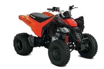
An all-terrain vehicle (ATV) is defined as a motorized off-highway vehicle designed to travel on four low-pressure or non-pneumatic tires, having a seat designed to be straddled by the operator and handlebars for steering control. ATVs are subdivided into two types as designated by the manufacturer,
Type I :- ATVs are intended by the manufacturer for use by a single operator and no passenger.
Type II:- ATVs are intended by the manufacturer for use by an operator and a passenger, and are equipped with a designated seating position behind the operator.
IMPORTANT COMPONENTS OF ALL TERRIAN VECICLES:
- VEHICLE BODY:
The vehicle body of ATV or also known as the ATV frame is like a foundation that attached to the axles and holds the engine of the ATV. It is crucial to have a good design of vehicle body that will it gives the ATV better traction for the driver especially diving in corners at high speeds. The ATV vehicle body has to be rigid enough to withstand the strains it might experience such as weight of the drivers. Depending on the conditions of the track, a dry track will require a stiffer vehicle body; whereas a wet track will require a more flexible vehicle body. Therefore, there a vehicle body are designed to have removal stiffening bars on the rear, front, and side of the ATV that can be removed or added depending on the track conditions.
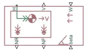
The block accounts for body mass, aerodynamic drag, road incline, and weight distribution between axles due to acceleration and road profile, optionally include pitch and suspension dynamics. The vehicle does not move vertically relative to the ground. The vehicle can also have a center of gravity (CG) that is at or below the plane of travel.
- SUSPENSION SYSTEM:
Suspension system is a broad term for any automobile system that allows each wheel on the same axle to move vertically independently of the others. "Independent" refers to the motion or path of movement of the wheels or suspension. The anti-roll bar ties the left and right suspension spring rates together but does not tie their motion together. Most modern vehicles have independent front suspension. Many vehicles also have an independent rear suspension. Some early independent systems used swing axle but modern systems use Chapman or Macpherson Struts, trilling arm, multilink or Wishbone. Independent suspension typically offers better race quality and handling characteristics, due to lower unsprung weight and the ability of each wheel to address the road undisturbed by activities of the other wheel on the vehicle.
- ENGINE:
Typical ATV will have two-stroke and four-stroke engines to choose from. Power is transmitted from the engine to the axle. Engine mounting is of flexible type. Any ATV engine can be mounted on the ATV, irrespective of its size and power. The flexible mounting consists of a metal tray directly attached to the Vehicle body on which the engine is mounted. Since the tray is directly attached to the vechicle body, the engine load is evenly distributed. The position of the tray can be changed by adjusting the nut bolt mechanism present in it.
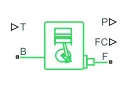
The Generic Engine block represents a general internal combustion engine. This block is a suitable generic engine for spark-ignition and diesel. Speed-power and speed-torque parameterizations are provided.
A throttle physical signal input specifies the normalized engine torque. Optional dynamic parameters include crankshaft inertia and response time lag. A physical signal port outputs the engine fuel consumption rate based on the fuel consumption model that you choose. Optional speed and redline controllers prevent engine stall and enable cruise control
- CONTINUOUSLY VARIABLE TRANSMISSION (CVT):
A continuously variable transmission (CVT) is an automatic transmission that can change seamlessly through a continuous range of gear ratios. This contrasts with other transmissions that provide a limited number of gear ratios in fixed steps.
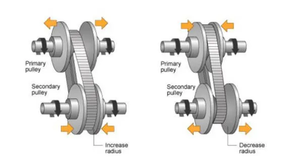
CVT uses two pulleys having variable diameters that help the transmission achieve infinite gear ratios. It tends to makes Over ride and Speed Reduction. The flow of power from the engine to wheels is continuous and uninterrupted. With no mechanical gears & shafts, the speed transition is smooth while accelerating or de-accelerating.
The most common type of CVT uses a V-Belt which runs between two variable-diameter pulleys. The pulleys consist of two cone-shaped halves that move together and apart. The V-belt runs between these two halves, so the effective diameter of the pulley is dependent on the distance between the two halves of the pulley. The V-shaped cross-section of the belt causes it to ride higher on one pulley and lower on the other; therefore, the gear ratio is adjusted by moving the two sheaves of one pulley closer together and the two sheaves of the other pulley farther apart.

The Variable Ratio Transmission block represents a gearbox that dynamically transfers motion and torque between the two connected driveshaft axes, the base and the follower. The port r represents the input signal.
- TIRES:
ATV has specific tires for dry or wet track so that drivers can have maximum performances and grips from the tires. Slick and wet tires are two main types tires used in karting. A slick tire does not have grooves on the tire. Slick tire is used when the track is dry. On the other hand, wet tires which are grooved are used in order to have more grips when the track is slippery. Hence, for track conditions that are in wet conditions, wet tire will be employed.

The Tire (Magic Formula) block models a tire with longitudinal behavior given by the Magic Formula, an empirical equation based on four fitting coefficients. The block can model tire dynamics under constant or variable pavement conditions.
- BRAKES:
The vehicle must be equipped with a braking system that is operated by a single control. Hydraulically actuated disc brakes are the most commonly used form of brake for motor vehicles. A hydraulic brake is an arrangement of braking mechanism which uses brake fluids, typically containing glyclo ethers, to transfer pressure from the controlling mechanism to the braking mechanism. The common arrangement of brake consist of brake pedal or lever, actuating rod, a master cylinder assembly and brake caliper assembly.

The Double-Shoe Brake block represents a frictional brake with two pivoted rigid shoes that press against a rotating drum to produce a braking action. The rigid shoes sit inside or outside the rotating drum in a diametrically opposed configuration. A positive actuating force causes the rigid shoes to press against the rotating drum. Viscous and contact friction between the drum and the rigid shoe surfaces cause the rotating drum to decelerate.
Double-shoe brakes provide high braking torque with small actuator deflections in applications that include motor vehicles and some heavy machinery. The model employs a simple parameterization with readily accessible brake geometry and friction parameter
- STREERING SYSTEM:
The steering system is designed to withstand the stress of the vehicle through any type of possible condition at the time of driving. The purpose of the steering system is to provide directional control of the vehicle with minimum input. Steering system must be controlled by a steering wheel which a continuous rim not incorporating any reflex angles in its basic shape.
PHYSICAL BLOCKS USED IN MODELLING OF ALL TERRIAN VEHICLE WITH CVT:
- Signal Builder - The Signal Builder block allows to create interchangeable groups of piecewise linear signal sources and use them in a model. In the Signal Builder window, create signals and define the output waveforms. In the signal builder the Brake input signal and Throttle input signals are created
- Simulink to PS converter - The simulink signals are converted into physical signals by using Simulink -PS converter.
- PS to Simulink Converter - Convert physical signal into Simulink output signal.
- Solver Configuration - The Solver Configuration block specifies the solver parameters that the model needs before begin simulation. Each topologically distinct Simscape block diagram requires exactly one Solver Configuration block to be connected to it.
- Goto - The Goto block passes its input to its corresponding From blocks. The input can be a real- or complex-valued signal or vector of any data type. From and Goto blocks allow you to pass a signal from one block to another without actually connecting them.
- From - The From block accepts a signal from a corresponding Goto block, then passes it as output. The data type of the output is the same as that of the input from the Goto block. From and Goto blocks allow you to pass a signal from one block to another without actually connecting them.
- Mechanical Rotational Reference - The Mechanical Rotational Reference block represents a reference point, or frame, for all mechanical rotational ports. All rotational ports that are rigidly clamped to the frame (ground) must be connected to a Mechanical Rotational Reference block.
- Ideal Rotational Motion Sensor - The Ideal Rotational Motion Sensor block represents an rotational motion sensor, that is, a device that converts an across variable measured between two mechanical rotational nodes into a control signal proportional to angular velocity or angle.
- Simple Gear - The Simple Gear block represents a gearbox that constrains the connected driveline axes of the base gear, B, and the follower gear, F, to co rotate with a fixed ratio that specify. Simple gear of base and follower wheels with adjustable gear ratio, friction losses, and triggered faults.
- PS Terminator - The PS Terminator block to cap physical signal output ports that do not connect to other blocks. Unlike conserving ports in physical modeling output ports, unconnected physical signal output ports do not generate warnings. However, a PS Terminator block for clarity, to indicate that the signal was not inadvertently left unconnected.
- Rotational Free End - The Rotational Free End block represents a mechanical rotational port that rotates freely, without torque. This block is used to terminate mechanical rotational ports on other blocks that want to leave unconnected.
- Connection Port - The Connection Port block transfers a physical connection or signal across subsystem boundaries.
- Inport blocks - Inport blocks link signals from outside a system into the system.
- Outport blocks - Outport blocks link signals from a system to a destination outside of the system. They can connect signals flowing from a subsystem to other parts of the model. They can also supply external outputs at the top level of a model hierarchy.
- The Step block - The Step block provides a step between two definable levels at a specified time. If the simulation time is less than the Step time parameter value, the block's output is the Initial value parameter value. For simulation time greater than or equal to the Step time, the output is the Final value parameter value.
- Constant block - The Constant block generates a real or complex constant value signal. This block to provide a constant signal input.
- PS Lookup Table (1D) - The PS Lookup Table (1D) block computes an approximation to function for a given data vectors. Both the input and the output are physical signals. The block generates output based on the input values using the selected interpolation and extrapolation methods.
- Knob block - The Knob block tunes the value of the connected block parameter to during simulation. When, connected the Knob block to a Gain block in model and adjust its value during simulation. Also, modify the range of the Knob block's scale to fit your data. The Knob block with other Dashboard blocks to create an interactive dashboard to control the model.
- Scope - Scope block display time domain signals, the scope displays simulation results for attached input signals.
CASE STUDIES:
The case studies includes Open loop and closed loop systems;
OPEN LOOP STUDY,
STUDY 1: MODELLING OF ALL-TERRIAN VEHICLE WITH CVT MODEL
STUDY 2: MODELLING OF ALL-TERRIAN VEHICLE WITH CVT MODEL WITH DASHBOARD
CLOSED LOOP STUDY,
STUDY 3: MODELLING OF ALL-TERRIAN VEHICLE WITH CVT MODEL LOOKUP TABLE
STUDY 4: MODELLING OF ALL-TERRIAN VEHICLE WITH CVT MODEL LOOKUP TABLE WITH DASHBOARD
GRABIT:
GRABIT Extracts data points from an image file. GRABIT starts a GUI program for extracting data from an image file. Multiple data sets can be extracted from a single image file, and the data is saved as an n-by-2 matrix variable in the workspace. It can also be renamed and saved as a MAT file.
EXTRACTING DATA POINT:
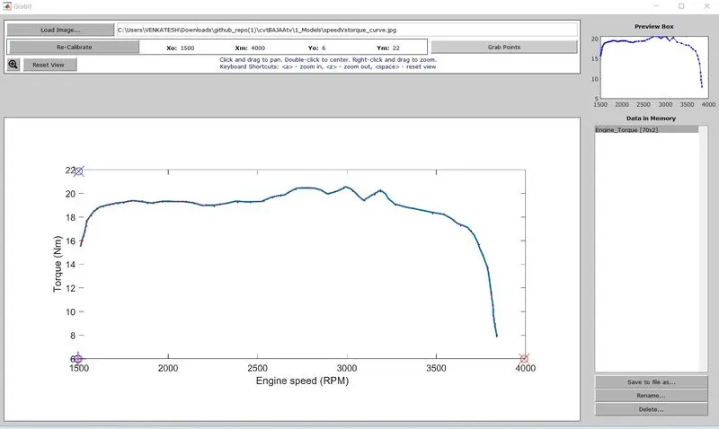
STEPS TAKEEN TO EXTRACT DATA POINTS FROM IMAGE:
- Load the Engine Torque-Speed curve into the GUI
- Calibrate axes dimensions. The X-Co-ordinate Minimum and Maximum values are been selected and Y- Co-ordinate Maximum and minimum values are selected.
- Grab points by clicking on points in the plots.
- Multiple data sets will remain in memory so long as the GUI is open. Variables can be renamed, saved to file, or edited in Array Editor.
- The data's are saved as from x-axis as Engine speedvector and y- axis as Torquevector.
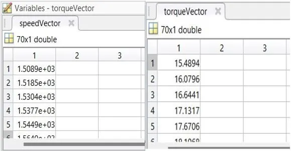
- The data points are extracted and saved as speed and torque vectors. The Extracted data points are then been used to feed in engine parameters.
OPEN LOOP SYSTEM:
STUDY 1: MODELLING OF ALL-TERRIAN VEHICLE WITH CVT MODEL:
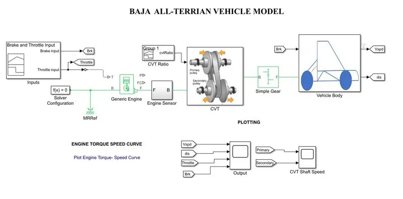
PROCESS FLOW EXPLANATIONS IN ALL-TERRIAN VEHICLE WITH CVT MODEL:
- SIGNAL BUILDER:
The input signals of brake and throttle inputs are assigned in the signal builder. Then the signals from the builder are conveted into physical siganl with the application of simulink to ps converter and feeded into engine system.
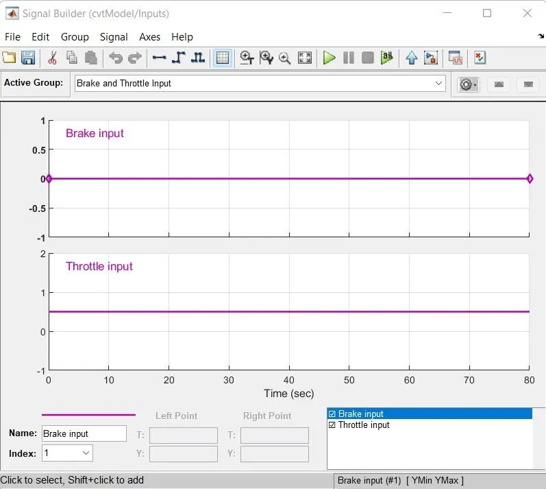
- The brake inputs are assigned as constant 0 throughout time of 80 seconds.
- Then the Throttle inputs are assigned as 0.5 throughout time of 80 seconds.
- In order to feed the throttle input into the Generic engine. And also the brake inputs are applied to the vehicle body.
2. GENERIC ENGINE:
- In the engine block the models are parameterized as tabulated torque data and the Extracted data's speed vector and torque vector are feeded from the base workspace.
- Then the engine are initialzed with initial velocity of 1750 rpm and with inertia.
- The Throttle constant input signal is feeded into the engine where the outputs of crankshaft are measured with the rotational motion sensor's
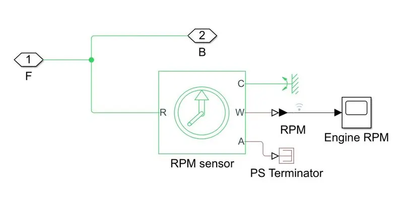
- The engine RPM from the crankshaft is measures as angular velocity and the angular position are terminmated using ps terminator block.
3. CVT RATIO:
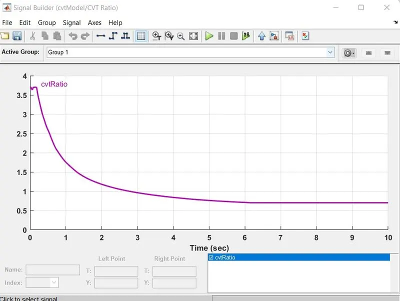
- The CVT ratio are provided with the time series data wit MAT file are imported into the signal builder to create signlas.
- Then the assigned signals are feeded into the Variable ratio transmission block where the gear ratio are changing accordingly based on the speed of the vehicle.
4. TRANSMISSION SUBSYSTEM:
- The output shaft from the engine are connected with the inertia where the rotational velocity of 2500 rpm and also subjected to mass m1.
- Then the base shaft is connected with the CVT block from which the shaftes are subjected to transmission stiffeness and the damping rate.
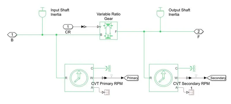
- The CVT ratio signals are assigned by the signal builder are feeded into the r port. Based upon the effect of parameters the base shaft with angular velocities are transmitted into the output shaft which are also subjected into inertia with mass m2.
- The angular velocities of input and output shaftes (primary and secondary pulley's) are measured with rotational motion sensor.
- The angular positions are terminated with ps terminator block.
- The secondary pulley (output) shaft is connected with the simple gear system for the speed reduction with the gear ratio of 10.
- From which the speed output from the crankshaft are normalized based upon CVT ratio and speed are reduced in the simple gear system. The follower shaft are then connected wit the vehicle body.
5. VEHICLE BODY:
- The Vehicle body block accounts for body mass, aerodynamic drag, road incline, and weight distribution between axles due to acceleration and road profile, optionally include pitch and suspension dynamics.
- The output shaft from the simple gear are subjected to inertia.
- The mass of the vehicle is subjected to 250 kg and number of wheels per axle are assigned.
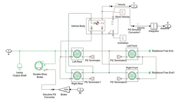
- The resulting traction motion developed by the tires are connected with the port H.
- The resultant force developed by the tires are connected with the port NR and NF.
- The brake input assigned with the signal builder are induced into the Double-shoe brake with the gain of 1000
- The resultant velocity of the vehicle are determined and are displayed with the scope block. Also, the distance of the vehicle are obtained with respect to the integration of time.
RESULTS:
- Based on the Throttle and brake input the velocity and distance of the vehicle body are plotted using scope block.
- When the brake are applied at the constant rate and Throttle are applied at constant rate 0.5.
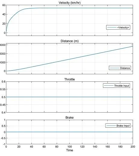
- Initially the Velocity of the vehicle are gradually increased and after certain point the velocity and speed of the vehilce are maintained at the constant.
- As, compared to the CVT secondary pulley are connected to the rear wheel where the plots are similar.
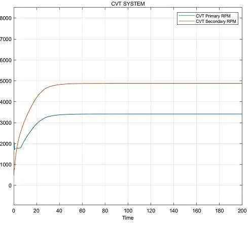
- From the plotting it is obsorved that when accelaration the assigned throttle input are feeded into the generic engine and with the CVT ratio, speed of the vehicle are manupulated and speeds are reduced witht a simple gear system.
OUTPUT OF ALL-TERRIAN VEHICLE WITH CVT MODEL:
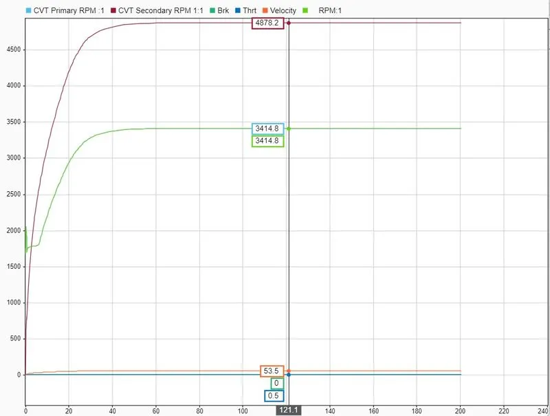
- Initially, the Brake, Throttle inputs are at constant state the engine with the velocity of 1750 rpm.
- Then the gradual increase in the velocity resulting the secondary pulley of the Variable transmission system are connected with the rear wheel of vehicle body
- It is noted that at constant accelarating the brake and throttle constant velocity is obtained after the gradual increase in the velocities with the gear ratio of 10.
STUDY 2: MODELLING OF ALL-TERRIAN VEHICLE WITH CVT AND DASHBOARD:
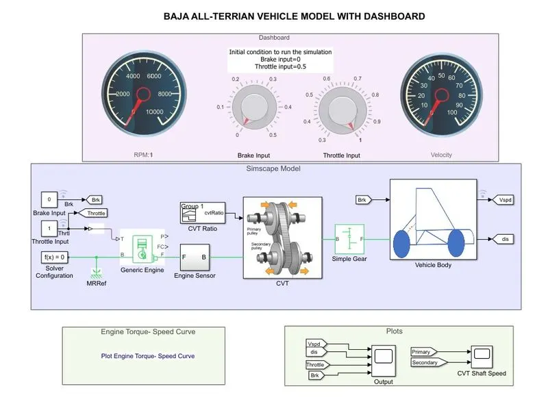
PROCESS FLOW EXPLANATIONS:
- In the model the signals are feeded using the knob which are connected with the constant block. The manual operation from the knob wheel accelarate throttle and brake inputs.
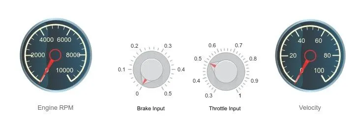
- The initial conditions are applied with the brake input as 0 and with the throttle input as 0.5
- The circular guage is used to monitor the engine rpm and velocity of the vehicle.
- Based upon the accelaration the RPM and velocity of the veicle are tunned.
- Then, throttle inputs are feeded into the generic engine and the speed and torque inputs are extracted using GRABIT and feeded into the engine system.
- The initial velocity of the vehicle are maintained as 1750 rpm with inertia.
- The output shaft from crankshft of engine are connected to motion sensor to measure the rated RPM of the engine with assigned Throttle input.
- The CVT ratio are imported from the MAT file and signals are builded using signal builder and feeded into the variable transmission ratio system.
- The output shaft is subjected to inertia with mass m1 and RPM is measured using rotational motion sensor which are connected to variable ratio transmisison.
- Based on the shaft speed the gear ratio are selected and the stiffness and damping are provided with the base shaft from the engine.
- After the CVT the output shaft are subjected to inertia where the shafts are connected to simple gear system with the gear ratio of 10.
- The ouput follower shaft is connected to the vechile body and are subjected to inertia.
- The resulting traction motion developed by the tires are connected with the port H.
- The resultant force developed by the tires are connected with the port NR and NF.
- The brake input assigned with the signal builder are induced into the Double-shoe brake with the gain of 1000
- The resultant velocity of the vehicle are determined and are displayed with the scope block. Also, the distance of the vehicle are obtained with respect to the integration of time.
RESULTS:
- Based on the Throttle and brake input the velocity and distance of the vehicle body are plotted using scope block.
- When the brake and throttle are applied by the varying time intervel.
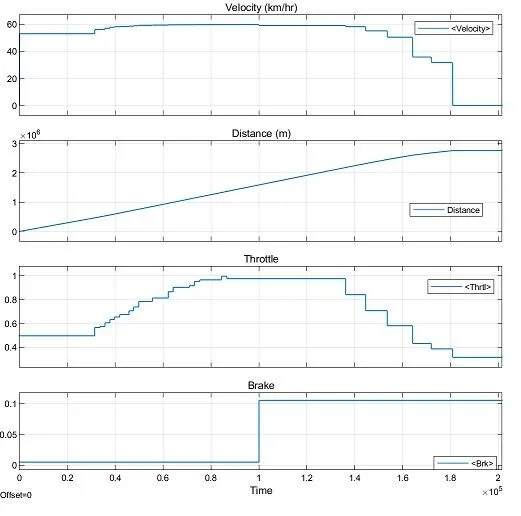
- Initially the Velocity of the vehicle are constant rate at throttle and brake inputs are maintained at same intervels.
- After, the increase in throttle the velocity of the vehicle also gets increasing with respect to time.
- When the brake is applied at a rate from 0 to 0.1 the velocity of the vehicle gets decresed at the point where the throttle at constant rate.
- As, compared to the CVT secondary pulley are connected to the rear wheel where the plots are similar.
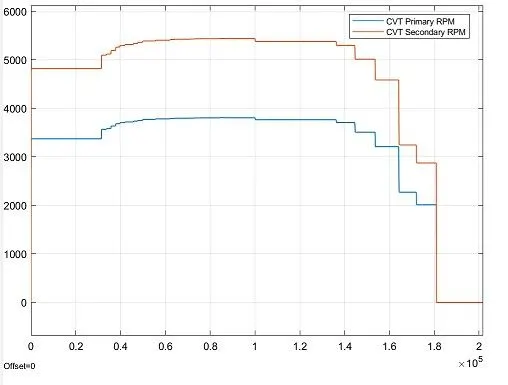
- From the plotting it is obsorved that when accelaration, the varied throttle input are feeded into the generic engine and with the CVT ratio, speed of the vehicle are manupulated and speeds are reduced with a simple gear system.
- In variable ratio gear, the primary and secondary pulley's are subjected to inertia and are varied based on the brake and throttle inputs.
OUTPUT OF ALL-TERRIAN VEHICLE WITH CVT MODEL WITH DASHBOARD:
- The data are inspected using Simscape data inspector. In which the parameters and the inputs are selected.
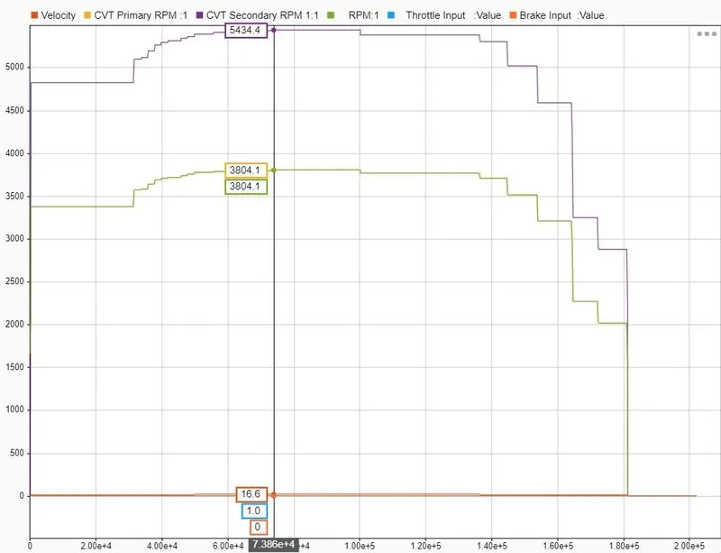
- Initially, the Brake, Throttle inputs are at constant state the engine with the velocity of 1750 rpm.
- Then the gradual increase in the velocity resulting the secondary pulley of the Variable transmission system are connected with the rear wheel of vehicle body
- It is noted that at variable accelaration of the brake and throttle the varied velocity is obtained after the gradual increase in the velocities with the gear ratio of 10.
- When the throttle input are assigned to 1 and brake inputs are assigned to 0. The velocities are varied based on the throttle inputs. It gets increasing when throttle the accelaration increases and decereases when throttle accelaration decreases.
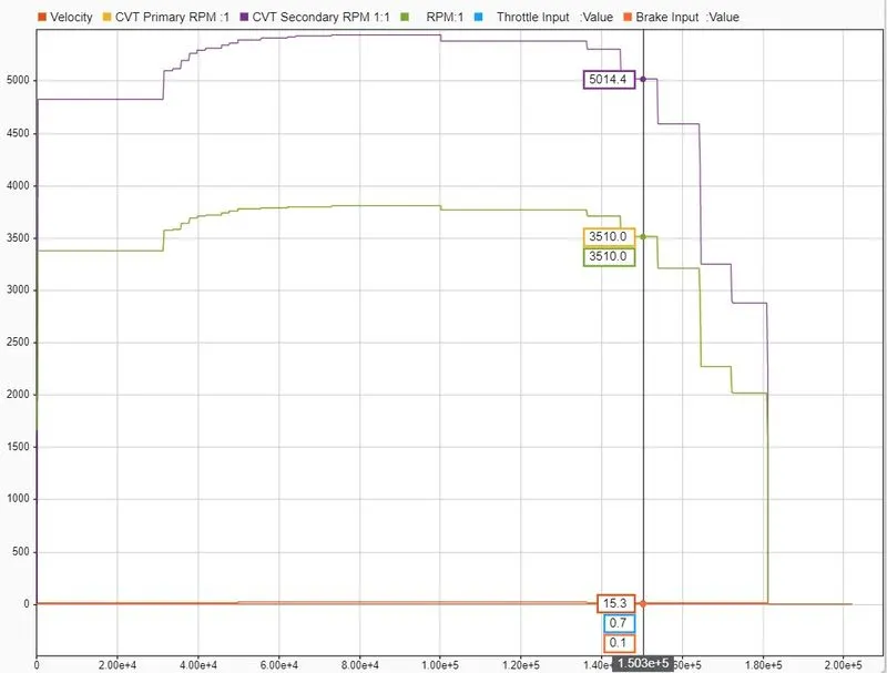
- When the throttle input are Varied from 0.3 to to 1 and brake inputs are assigned to 0.1. The velocities are varied based on the throttle inputs. It gets increasing when throttle accelaration increases and decereases when throttle accelaration decreases.
- The point where the brake is applied the velocity and variable transmission ratio pulley's are varied based on the CVT ratio provided.
CLOSED LOOP SYSTEM:
STUDY 3: MODELLING OF ALL-TERRIAN VEHICLE WITH CVT AND LOOKUP TABLE:
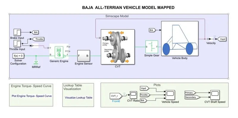
PROCESS FLOW EXPLANATIONS IN ALL-TERRIAN VEHICLE WITH CVT MODEL:
1. INPUT SIGNAL:
- The brake and throttle inputs are assigned using step block.
- The step block are assigned with the step time, initial value and final values.
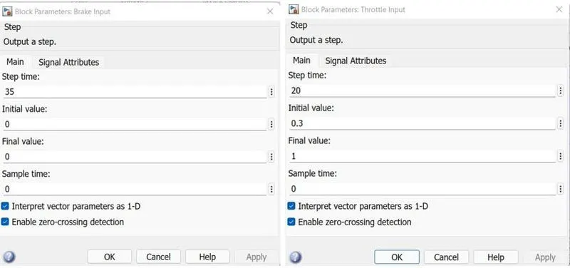
- The Throttle signals are feeded into the generic engine system and the brake input are fedded into the vehicle body.
- The speed and torque inputs are extracted using GRABIT and feeded into the engine system.
- The initial velocity of the vehicle are maintained as 1600 rpm with inertia 5 kg m^2.
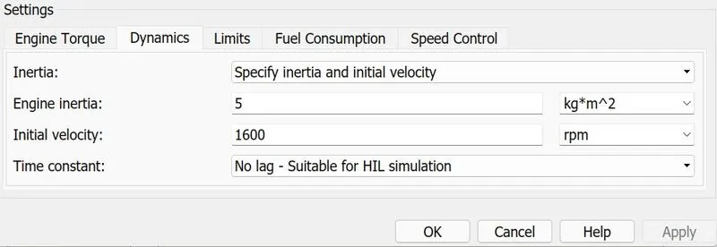
- The output shaft from crankshft of engine are connected to motion sensor to measure the rated RPM of the engine with assigned Throttle input.
- The CVT ratio are assigned from the MAT file and PS 1-D lookup table is used to feed the data's into the variable transmission ratio system.
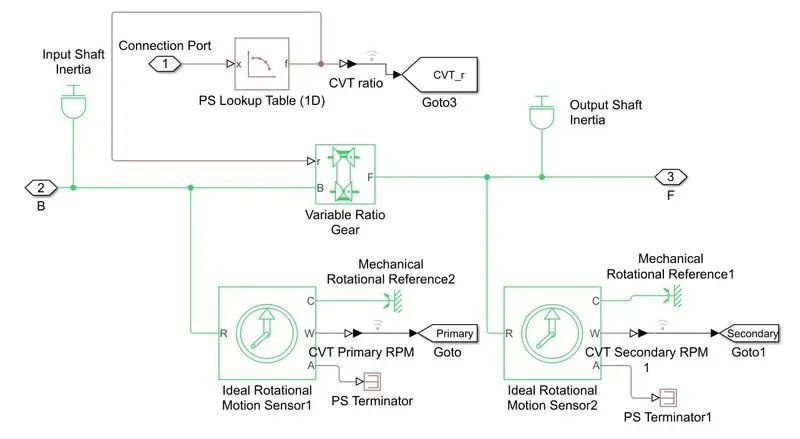
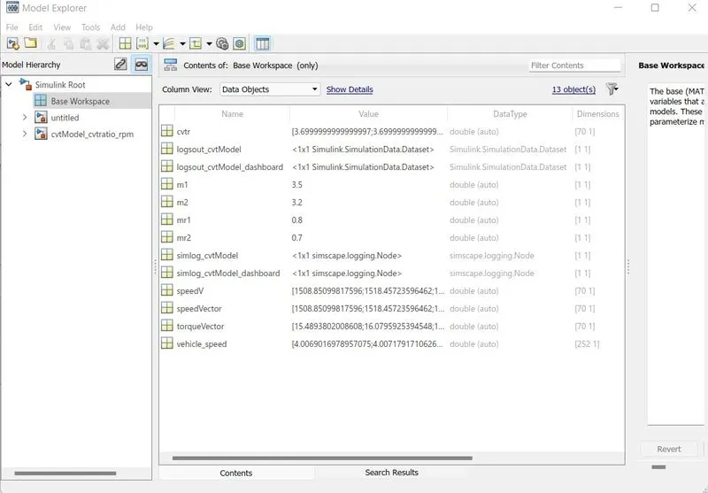
- The CVT ratio and vehicle speed are provided in the MAT data and are imported into the base workspace to initialze the CVT ratio.
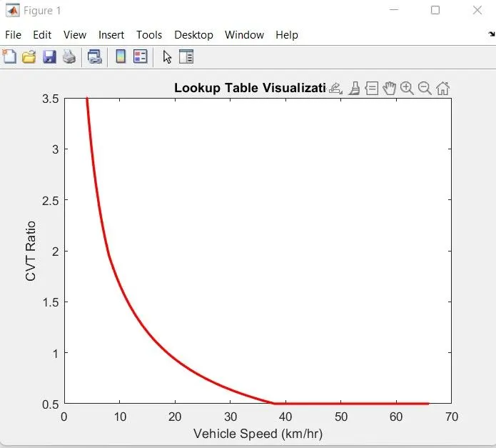
- Based upon the vehicle speed the CVT ratio's are mapped using PS 1-D look up table.
- The output shaft is subjected to inertia with mass m1 and RPM is measured using rotational motion sensor which are connected to variable ratio transmisison.
- Based on the shaft speed the gear ratio are selected and the stiffness and damping are provided with the base shaft from the engine.
- After the CVT the output shaft are subjected to inertia where the shafts are connected to simple gear system with the gear ratio of 12.
- The ouput follower shaft is connected to the vechile body and are subjected to inertia.
- The resulting traction motion developed by the tires are connected with the port H.
- The resultant force developed by the tires are connected with the port NR and NF.
- The brake input assigned with the signal builder are induced into the Double-shoe brake wit the gain of 1000
- The resultant velocity of the vehicle are determined and are displayed with the scope block. Also, the distance of the vehicle are obtained with respect to the integration of time.
RESULTS:
- Based on the Throttle and brake input the velocity and distance of the vehicle body are plotted using scope block.
- When the brake and throttle are assigned by the step block with varying time step.
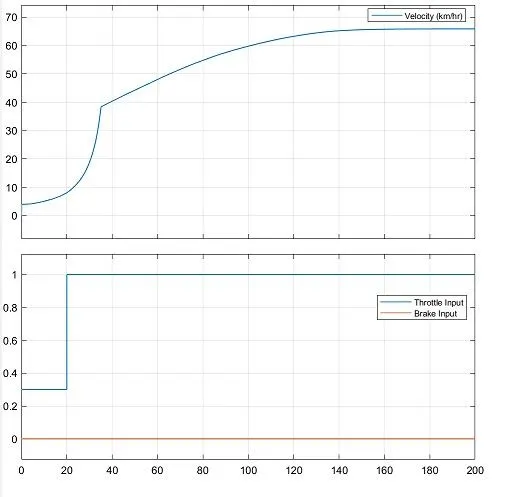
- Initially the Velocity of the vehicle are gradually increased at throttle inputs are constant till 20 seconds and brake inputs are constant throughout.
- After, the increase in throttle the velocity of the vehicle also gets increasing wit respect to time.
- As, compared to the CVT secondary pulley are connected to the rear wheel where the plots are similar.
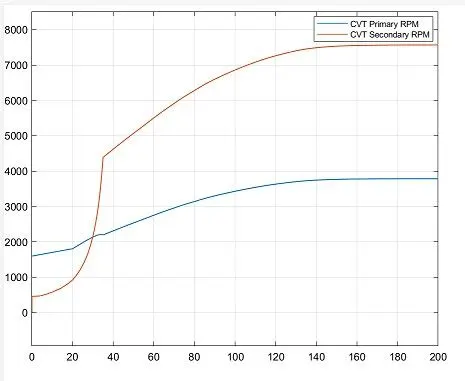
- From the plotting it is obsorved that when accelaration, the varied throttle input are feeded into the generic engine and with mapped CVT ratio based on closed loop system the velocity is mapped CVT ratio and speeds are reduced with a simple gear system.
- In variable ratio gear, the primary and secondary pulley's are subjected to inertia and are varied based on the brake and throttle inputs.
- The CVT ratio's are mapped based on the velocity of the vehicle.
OUTPUT OF ALL-TERRIAN VEHICLE WITH CVT MODEL WITH LOOK UP TABLE:
- The data are inspected using Simscape data inspector. In which the parameters and the inputs are selected.
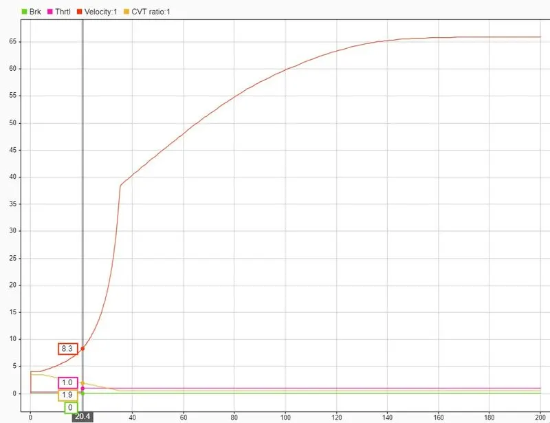
- Initially, the Brake, Throttle inputs are at constant state the engine with the velocity of 1600 rpm.
- Then the gradual increase in the velocity resulting the secondary pulley of the Variable transmission system are connected with the rear wheel of vehicle body
- It is noted that at accelaration of throttle the varied velocity is obtained after the gradual increase in the velocities with the gear ratio of 12.
- The velocities mapped the CVT ratio and that drives the variable transmission ratio system.
- When the throttle input are varied and brake inputs are assigned to 0. The velocities are varied based on the throttle inputs. It gets increasing when throttle are accelaration increases and decereases when throttle accelaration decreases.
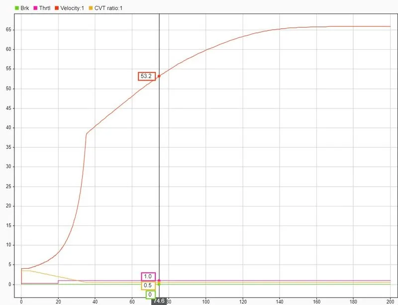
- When the throttle input are Varied and brake inputs are assigned to 0. The velocities are gradually increasing based on the mapped CVT ratio from te velocities. It gets increasing when throttle are accelaration increases and decereases when throttle accelaration decreases.
- The throttle inputs the generic engine and the crankshaft outputs are connected to the variable transmission ratio with inertia and are mapped with CVT ratio based on Vehicle velocity.
- The velocity gets gradual increase when the speed of the vehilce velocity increases gradually and are mapped by the CVT ratio.
STUDY 4: MODELLING OF ALL-TERRIAN VEHICLE WITH CVT AND LOOKUP TABLE WITH DASHBOARD:
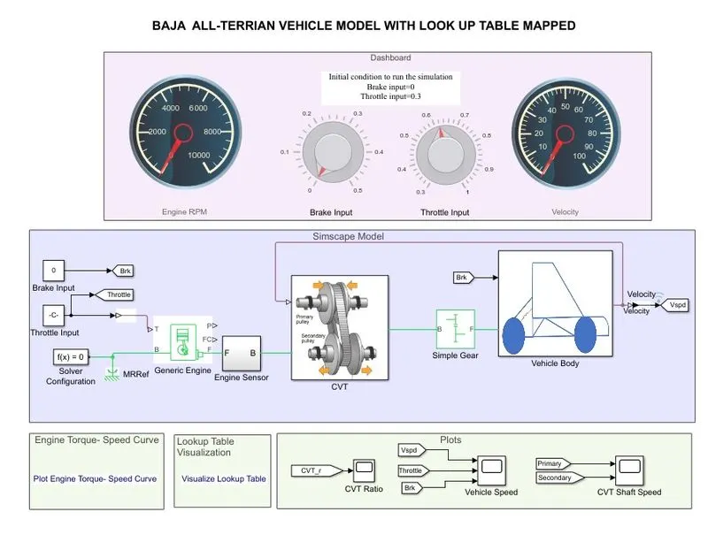
PROCESS FLOW EXPLANATIONS:
- In the model the signals are feeded using the knob which are connected with the constant block. The manual operation from the knob wheel accelarate throttle and brake inputs.
- The initial conditions are applied with the brake input as 0 and with the throttle input as 0.5
- The circular guage is used to monitor the engine rpm and velocity of the vehicle.
- Based upon the accelaration the RPM and velocity of the vehicle are tunned.
- Then, throttle inputs are feeded into the generic engine and the speed and torque inputs are extracted using GRABIT and feeded into the engine system.
- The initial velocity of the vehicle are maintained as 1600 rpm with inertia 5 kg m^2. .
- The output shaft from crankshft of engine are connected to motion sensor to measure the rated RPM of the engine with assigned Throttle input.
- The CVT ratio are assigned from the MAT file and PS 1-D lookup table is used to feed the data's into the variable transmission ratio system.
- The CVT ratio and vehicle speed are provided in the MAT data and are imported into the base workspace to initialize the CVT ratio.
- Based upon the vehicle speed the CVT ratio's are mapped using 1-D look up table.
- The output shaft is subjected to inertia with mass m1 and RPM is measured using rotational motion sensor which are connected to variable ratio transmisison.
- Based on the shaft speed the gear ratio are selected and the stiffness and damping are provided with the base shaft from the engine.
- After the CVT the output shaft are subjected to inertia where the shafts are connected to simple gear system with the gear ratio of 12.
- The ouput follower shaft is connected to the vechile body and are subjected to inertia.
- The resulting traction motion developed by the tires are connected with the port H.
- The resultant force developed by the tires are connected with the port NR and NF.
- The brake input assigned with the signal builder are induced into the Double-shoe brake wit the gain of 1000
- The resultant velocity of the vehicle are determined and are displayed with the scope block. Also, the distance of the vehicle are obtained with respect to the integration of time.
RESULTS:
- Based on the Throttle and brake input the velocity and distance of the vehicle body are plotted using scope block.
- When the brake and throttle are applied by the varying time intervel.
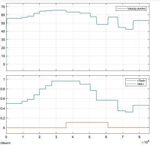
- Initially the Velocity of the vehicle are gradually increased at throttle inputs are constant to certain time intervel and are varied using knob and brake inputs are constant throughout and varied at certain time intervel using knob.
- After, the increase in throttle the velocity of the vehicle also gets increasing with respect to time.
- As, compared to the CVT secondary pulley are connected to the rear wheel where the plots are similar.
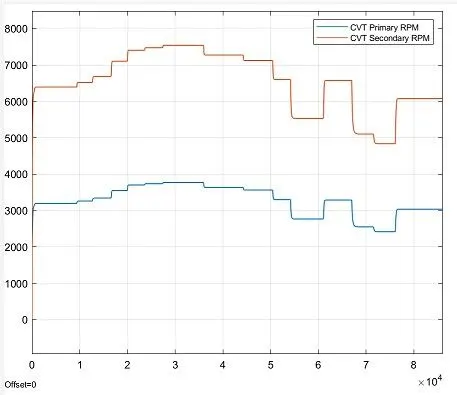
- From the plotting it is obsorved that when accelaration, the varied throttle input are feeded into the generic engine and with mapped CVT ratio based on closed loop system the velocity is mapped CVT ratio and speeds are reduced with a simple gear system.
- In variable ratio gear, the primary and secondary pulley's are subjected to inertia and are varied based on the brake and throttle inputs.
- The CVT ratio's are mapped based on the velocity of the vehicle.
OUTPUT OF ALL-TERRIAN VEHICLE WITH CVT MODEL WITH LOOK UP TABLE AND DASHBOARD:
- The data are inspected using Simscape data inspector. In which the parameters and the inputs are selected.
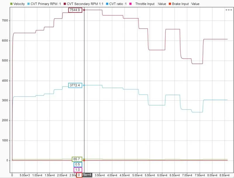
- Initially, the Brake, Throttle inputs are at constant state the engine with the velocity of 1600 rpm.
- Then the gradual increase in the velocity resulting the secondary pulley of the Variable transmission system are connected with the rear wheel of vehicle body
- It is noted that at accelaration of throttle the varied velocity is obtained after the gradual increase in the velocities with the gear ratio of 12.
- The velocities mapped the CVT ratio and that drives the variable transmission ratio system.
- When the throttle input are varied and brake inputs are assigned to 0. The velocities are varied based on the throttle inputs. It gets increasing when throttle are accelaration increases and decereases when throttle accelaration decreases.
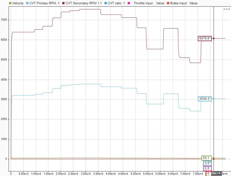
- When the throttle input are Varied and brake inputs are assigned to 0. The velocities are increasing based on the mapped CVT ratio from tHe velocities. It gets increasing when throttle accelaration increases and decereases when throttle accelaration decreases.
- The throttle inputs the generic engine and the crankshaft outputs are connected to the variable transmission ratio with inertia and are mapped with CVT ratio based on Vehicle velocity.
- The velocity gets gradual increase when the speed of the vehilce velocity increases gradually and are mapped by the CVT ratio and decreases accordingly.
CONCLUSION:
- The technical report explaining the model properties are prepared.
- The modelling of open loop and closed loop systems are been carried out.
- The modellling of an ATV with CVT Model carried out.
- The modellling of an ATV with CVT model with Dashboard carried out.
- The modellling of an ATV with CVT model with Look up table carried out.
- The modellling of an ATV with CVT model with Look up table and with Dashboard are carried out.
- The Validation on the effect of parameters and CVT ratio in All-Terrian Vehicle are carried out.
REFERENCES: