Roof Design
ROOF ASSEMBLY DESIGN
AIM:
To Create an Roof Assembly by developing the essential flanges for the outer Roof with Reinforcements and to perform the calculation for the positions of Bow Roofs and perform Draft Analysis.
OBJECTIVE:
- To Create an Assembly for the Roof Outer by developing essential flanges.
- To Create Reinforcements by performing calculations for the position of Bow Roofs.
- To Analyse the draft on the Reinforcements and Roof Outer, Front Roof Rail, Rear Roof Rail, Center Roof rail and Bow Roof Rails.
- To do a curvature study on the Roof.
- To Suggest and Implement the remedies if position of criterion is Not fullfilling.
- To Create a Roof Ditch Area with the tool opening angle of 7 degeree.
- To develop the Reinforcements (Front Roof Rail, Rear Roof Rail, Center Roof rail and Bow Roof Rails) as seperate Parts.
- To Design the Front Roof Rail, Rear Roof Rail, Center Roof rail and Bow Roof Rails by following the Master sections.
JUDGEMENT CONDITIONS:
- Heat Distortion Condition:- value < 2.7
- Snow Load Condition :- Value > 3.1
INTRODUCTION:
BODY IN WHITE (BIW):
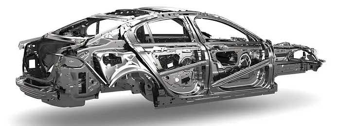
In the Automotive Industry BIW (Body in White) is the common terminology used to mention the car sheet metal welded structure (body shell). Sub-assemblies like Under body, Body side Left Hand Side/ Right Hand Side, Front End, Roof etc. gets welded together by various metal joining process like resistance spot welding, Laser welding, MIG welding to make welded metal shell (Without Door, Trunk-lid / Tailgate) , Fender, Hood) called Body in White. Automotive car shell made before painting is called Body in White.
ROOF:
An automobile roof or car top is the portion of an automobile that presents above the passenger compartment, protecting the vehicle occupants from the sun, wind, rain and other external elements or environment conditions.
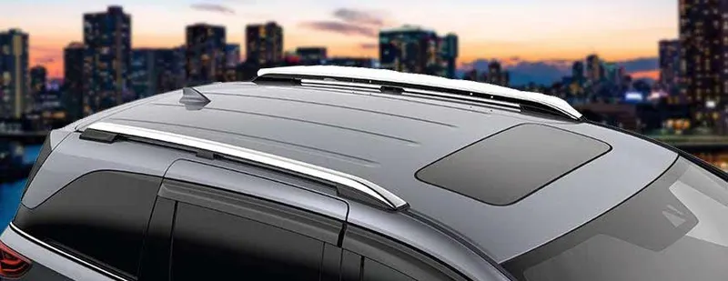
The roof is joined with the pillars (A-Piller, B-Piller, C- Pillers) on all sides, and the roof is reinforced with the front roof rail, rear roof rail, bow roofs and Center Roof Rails. The rails are joined with the roof with the help of mastic sealant and welding process which will not affect the aesthetic look of roof surface.
DIFFERENT TYPES OF ROOFS:
The Roofs are classified into Various types based on the Structural and Requirements,
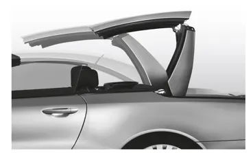
(1). CONVERTABLE ROOF:
The convertible roofs are of a folding construction framework with the actual top made from cloth or other fabric. Other types of convertible roofs include retractable hardtops which are often constructed from metal or plastic and detachable hardtops where a metal or plastic roof is manually removed and often stored in the trunk.
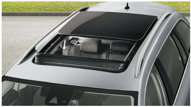
(2). SUN ROOF:
A sunroof is a movable panel that opens to uncover a window in an automobile roof, allowing light and fresh air to enter the passenger compartment. Sunroofs can be manually operated or motor driven, and are available in many shapes, sizes and styles. While the term sunroof is now used generically to describe any glass panel in the roof.
(3). T - TOP ROOFS:
A T-top is an automobile roof with a removable panel on each side of a rigid bar running from the center of one structural bar between pillars to the center of the next structural bar. The panels of a traditional T-top are usually made of auto grade safety glass.
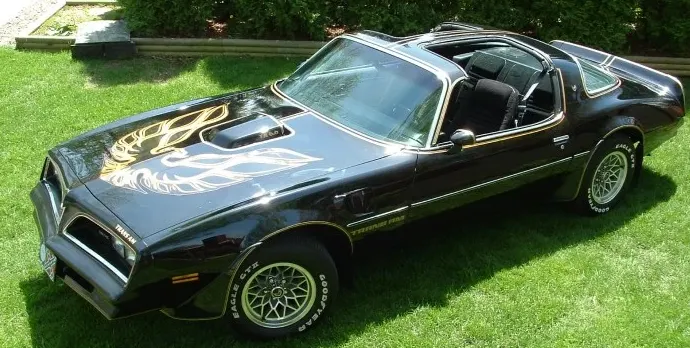
(4). TARGA TOP ROOFS:
Targa top, or targa for short, is a semi-convertible car body style with a removable roof section and a full width roll bar behind the seats.
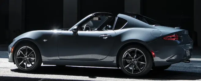
(5). VINYL TOP ROOFS:
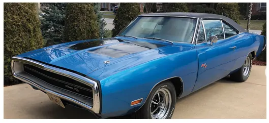
This covering was originally designed to give the appearance of a convertible to models with a fixed roof, but eventually it evolved into a styling statement in its own right. Vinyl roofs were most popular in the American market.
ROOF TEST REGULATIONS AND REQUIREMENTS:
(1) . ROLL OVER TEST:
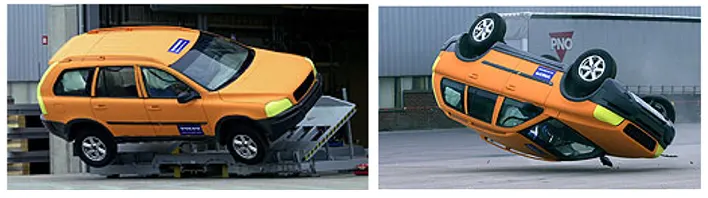
The operation is a simulation of the driver overdoing the vehicle steering, usually happens during emergency situations. The rollover test conducted by NHTSA subjects vehicles to a handling maneuver called a fishhook, which is a term used for a quick left-right turn at speeds ranging from 35 to 50 miles per hour.
(2). ROOF CRUSH TEST:
To measure the roof strength of a vehicle, IIHS has a metal plate pushed against one corner of a vehicle’s roof at a constant speed. The maximum force sustained by the roof before five inches of crush is compared to the vehicle’s weight. From there, IIHS calculates a strength-to-weight ratio.
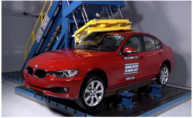
Roof strength evaluations are conducted on a quasi-static test system. The vehicle roof front corner to holds a quasi-static force more than 1.5 times of the unloaded vehicle weight, up to 127mm of displacement. This 1.5 is known as the SWR (strength to weight ratio)of the vehicle.
DESIGN CONSIDERATIONS FOR ROOF:
- Visibility Criteria.
- Head Room Clearence.
- Curvatue Study of Roof.
- Heat Distortion Prediction.
- Snow Load Prediction.
These are the Design considerations, while designing the roof outer, Front Roof Rails, Rear Roof Rails, Bow Roof Rails, Center Roof Rails the considerations are been taken into account.
DIFFERENT MANUFACURING PROCESSES:
The most important design consideration of any component is manufacturing aspect. In sheet metal, the component is manufactured by press tool dies. The Press tool is stamping which includes cutting operations like shearing, piercing etc. and forming operations like bending, Deep drawing, hemming etc.
FORMING PROCESS:
Forming describes the process of transforming the flat metal into another shape by applying force. It is accomplished in one of several ways, depending on the design specifications for the part. With a series of operations, the metal can be altered from a relatively simple shape into a complex one.
DEEP DRAWING:
The deep drawing is used to manufacture a product with seamless, complex shapes. This is tool related manufacturing process where the metal is stretched or extended between two tool halves to create prospective shape.
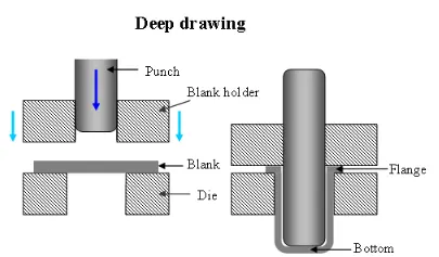
The process involves a punch with a round comer and a die with a large radius. The punch-die clearance is slightly larger than the thickness of the sheet metal to be deep drawn. As the load applied through the punch, the sheet metal is forced to flow radially and sink into the die cavity to form a cup. The process is best suitable for complex shaped problems. Deep drawing is one of the most widely used processes in sheet metal forming. Apart from its use in many other sectors, it is applied in the automotive industry for the manufacturing of car body parts.
BLANKING AND PIERCING:
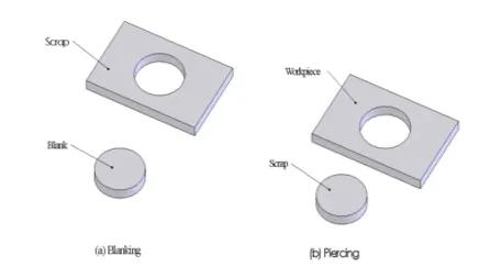
Blanking and piercing are the shearing processes in which a punch and die are used to produce parts from coil or sheet stock. The blanking produces the outside features of the component, while piercing produces internal holes or shapes.
EMBOSSING:
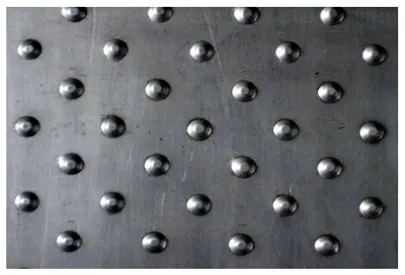
Sheet metal embossing is a stamping process for producing raised or sunken designs or relief in sheet metal. This process can be made by means of matched male and female roller dies, or by passing sheet or a strip of metal between rolls of the desired pattern.
APPLICATIONS OF SHEET METAL STAMPING PROCESS:
- In the stamping process, sheet metal is transformed into complex parts using highly specialized computer-aided drafting and manufacturing programs.
- Sheet metal stamping produces superior, resilient, heavy-duty parts quickly and efficiently.
- The results are so precise, they’re typically more reliable and consistent than manual machining.
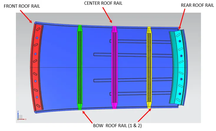
MAIN PARTS OF ROOF DESIGN:
(1). Roof Outer
(2). Front Roof Rail
(3). Center Roof Rail
(4). Bow Roof Rails (1 & 2)
(5). Rear Roof Rails
INPUTS - ROOF STYLING SKIN PART:
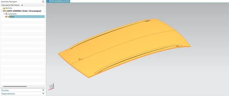
CREATION OF ROOF OUTER:
The Rood Outer is Created by using the given Styling Skin data of the roof, by which the protions are been sectioned and outer roof is created with the opening angle of 7 Degeree.
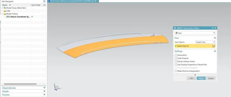
By using the Wave geometry linker the faces are been selected to create a linked face on the activated outer roof.
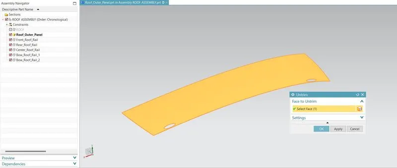
By using the Untrim command, the faces are been selected to Untrim the linked face of outer roofs.
MASTER SECTION:
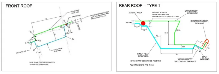
By following the Master section, the outer roof, essential flanges are been created with the ditch area opening angle of 7 degree.
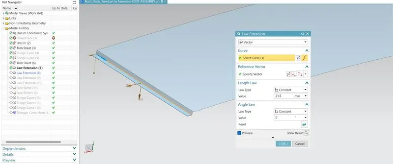
The law extension is used to create the extended sheet at an defined angle of 7 degeree, by selecting the curve and respective directions.
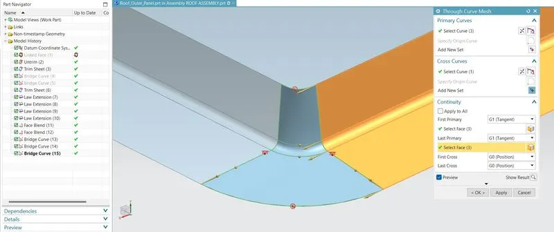
By using the Through curve mesh command, the Tangent curves and the cross curves are been selected to create a continuty between two selected sheets.
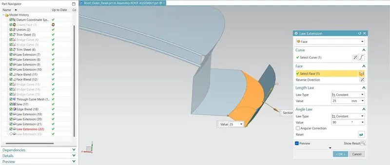
As per the Master section the, Flanges are been created on the outer roof, for the ditch area for welding the roof rails with the outer panels.
DRAFT ANALYSIS:
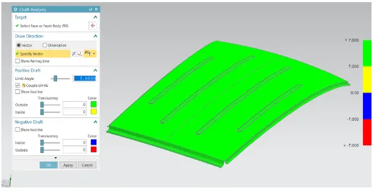
By selecting the respective body faces and the vector the draft analysis has been done on the Outer Roof at 7 degerees.
CREATION OF FRONT ROOF RAILS:
MASTER SECTION:
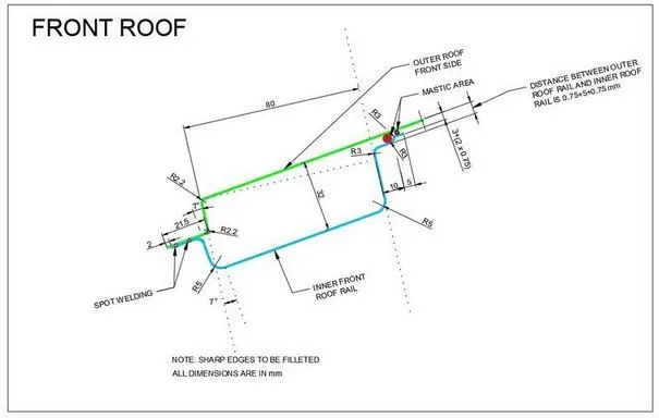
By following the Master section, the Front Roof Rail, essential flanges are been created with the ditch area from the roof outer.
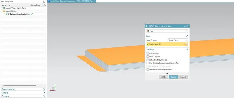
By using the Wave geometry linker, the outer roof linked faces are been selected with the ditch area to create the front roof rails as per the Master Sections.
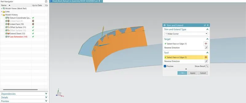
As per the Master section, the lined faces are been offsetted to the respective distance and using the law extension the flanges are been created at an angle and by using the trim and extend feature the sheets are been created as corners.
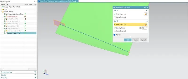
By uisng the Datum plane on curve and the INtersecton curve the line through points are been created and projected on the sheet to create the front roof rails as per Master section required distance of @ 80 mm.
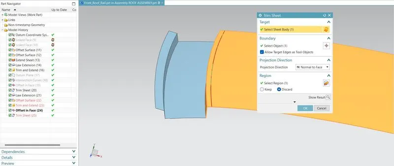
By using tthe trim sheet command the projected curve are been selected as boundary and faces are been selected to trim off the sheets.
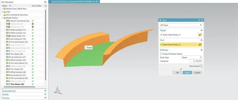
By using the sew and edge blend commands, the disjointed portions are been joined together and edges are been filleted respectively.
DRAFT ANALYSIS:
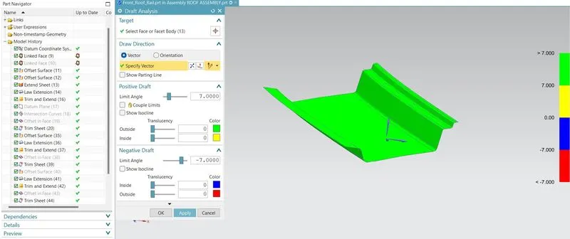
By selecting the respective body faces and the vector the draft analysis has been done on the front roof rail at 7 degerees.
CREATION OF BOW ROOF RAIL - 1:
MASTER SECTION:
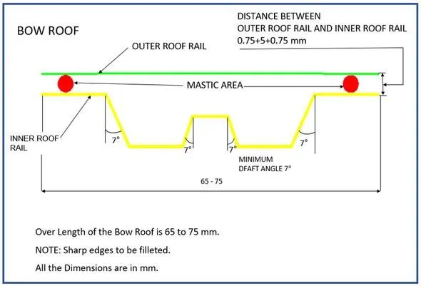
By following the Master section, the Bow Roof Rail -1, essential flanges are been created with the ditch area from the roof outer.
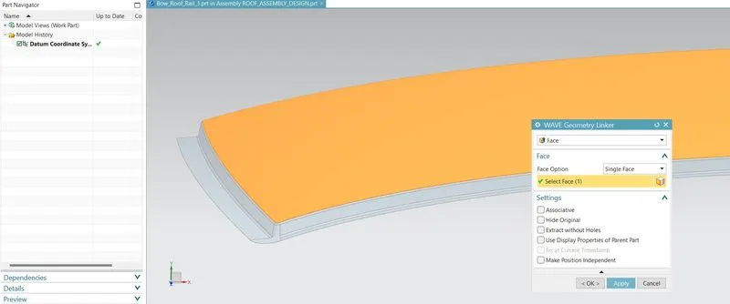
By using the Wave geometry linker, the outer roof linked faces are been selected with the ditch area to create the Bow roof rails as per the Master Sections.
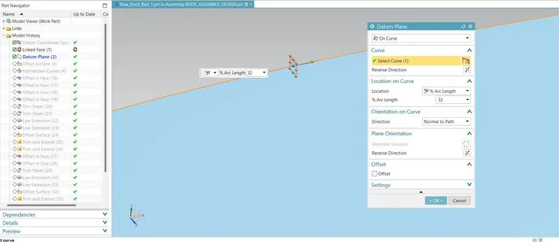
As per the Master section, the linked faces are been offsetted to the respective distance and using datum plane the distance are been created.
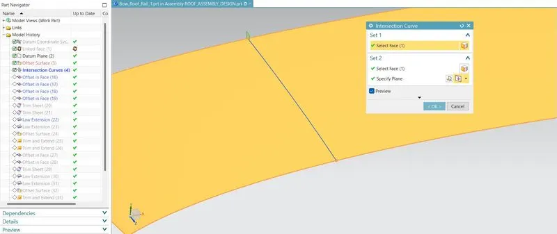
By using the Datum plane on curve and the Intersecton curve the line through points are been created and projected on the sheet to create the Bow roof rails as per Master section required distance.
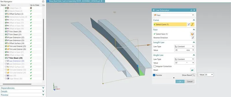
By using tthe trim sheet command the projected curve are been selected as boundary and faces are been selected to trim off the sheets and uisng the law extension command the flanges are been created as per the Master section and fllleted @ the respective edges by 3.75 mm.
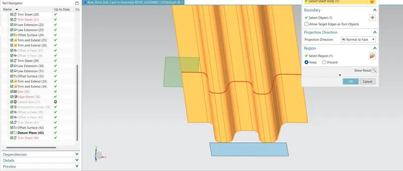
By using Datum plane @ the required length, and uisng the trim sheet command sheets are been trimmed off and using the ditch area from the outer roof are been connected with the Bow roof rails.
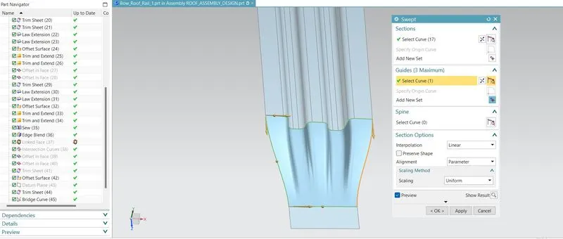
By using the bridge curve command the, faces are been selecetd and using the swept feature the curve and guides are been selected to create a Bow roof rails.
DRAFT ANALYSIS:
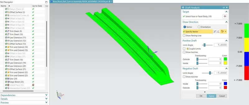
By selecting the respective body faces and the vector the draft analysis has been done on the Bow Roof rails at 7 degerees.
CREATION OF CENTER ROOF RAILS:
MASTER SECTION:
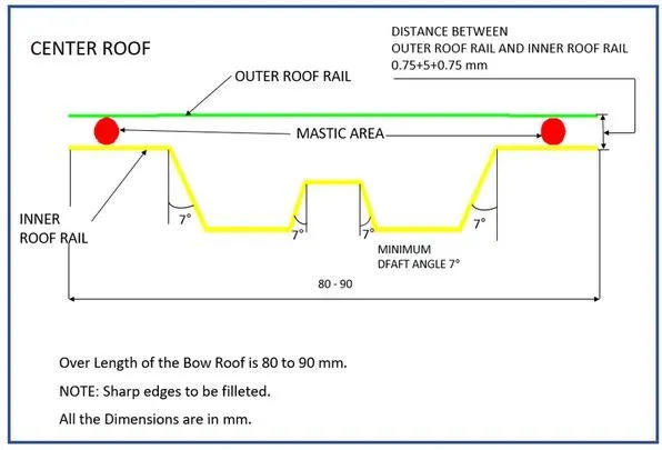
By following the Master section, the Center Roof Rail, essential flanges are been created with the ditch area from the roof outer.
By using the Wave geometry linker, the outer roof linked faces are been selected with the ditch area to create the center roof rails as per the Master Sections.
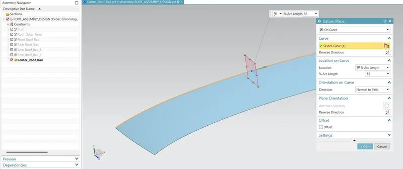
As per the Master section, the linked faces are been offsetted to the respective distance and using datum plane the distance are been created.
By using the Datum plane on curve and the Intersecton curve the line through points are been created and projected on the sheet to create the center roof rails as per Master section required distance.
By using tthe trim sheet command the projected curve are been selected as boundary and faces are been selected to trim off the sheets and using the law extension command the flanges are been created as per the Master section and fllleted @ the respective edges by 3.75 mm.
By using Datum plane @ the required length, and using the trim sheet command sheets are been trimmed off and using the ditch area from the outer roof are been connected with the center roof rails.
By using the bridge curve command the, faces are been selecetd and using the swept feature the curve and guides are been selected to create a Center roof rails.
DRAFT ANALYSIS:
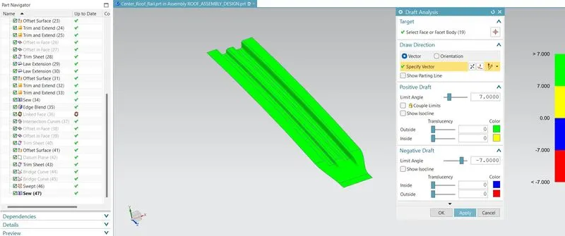
By selecting the respective body faces and the vector the draft analysis has been done on the Center Roof rails at 7 degerees.
CREATION OF BOW ROOF RAIL - 2:
MASTER SECTION:
By following the Master section, the Bow Roof Rail -2, essential flanges are been created with the ditch area from the roof outer.
By using the Wave geometry linker, the outer roof linked faces are been selected with the ditch area to create the Bow roof rails as per the Master Sections.
As per the Master section, the linked faces are been offsetted to the respective distance and using datum plane the distance are been created.
By using the Datum plane on curve and the Intersecton curve the line through points are been created and projected on the sheet to create the Bow roof rails as per Master section required distance.
By using tthe trim sheet command the projected curve are been selected as boundary and faces are been selected to trim off the sheets and uisng the law extension command the flanges are been created as per the Master section and fllleted @ the respective edges by 3.75 mm.
By using Datum plane @ the required length, and uisng the trim sheet command sheets are been trimmedoff and using the ditch area from the outer roof are been connected with the Bow roof rails.
By using the bridge curve command the, faces are been selecetd and using the swept feature the curve and guides are been selected to create a Bow roof rails.
DRAFT ANALYSIS:
By selecting the respective body faces and the vector the draft analysis has been done on the Bow Roof rails at 7 degerees.
CREATION OF REAR ROOF RAILS:
MASTER SECTION:
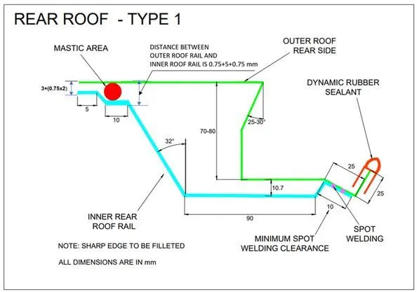
By following the Master section, the Rear Roof Rail, essential flanges are been created with the ditch area from the roof outer.
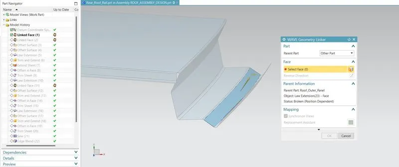
By using the Wave geometry linker, the outer roof linked faces are been selected to create the Rear roof rails as per the Master Sections.
The linked faces are been offsetted to the respective distance and using datum plane the distance are been created.
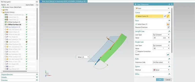
By using the law extension @ respective angles, the flanges are been cretaed as per the Master section and respective distances. The faces from the outer roof are been selected as linked geometry and used as a offseted sheets to create a Rear roof rails.
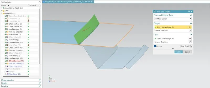
By using the trim ad extend command the flanges are been created as per the Master section and fllleted @ the respective edges by 3.75 mm.
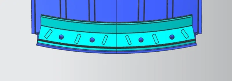
MIRRORING ROOF AND REINFORCEMENTS:
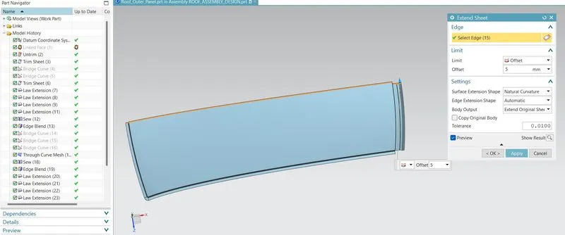
By using the Extend sheet command the Outer roof, Front Roof Rail, Center Roof Rail, Bow Roof rail and Rear Roof Rails are been extended to the minimum distance of 5 mm.
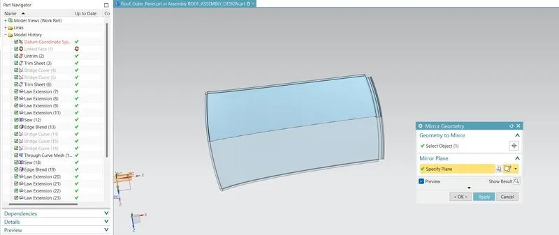
After Extending the respective sheets, Using the Mirror geometry feature the faces to be mirrored are been selected and also plane to mirror the object are been selected to Mirror.
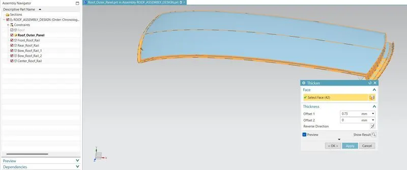
By using the Thicken command the facea are been selected to Thicken @ 0.75 mm for oter roofs and all other reinforcements (Front Roof Rail, Center Roof Rail, Bow Roof rail and Rear Roof Rails).
ASSEMBLY OF ROOF:
CURVATURE STUDY ON THE ROOF:
(1). HEAT DISTORTION PREDICTION:
Heat distortion temperature is the temperature at which metal softens and deform under a specific load. This study is used to avoid bending or damage to roof based on heat distortion temperature. This study is used to justify the position of bow roofs in order to strengthen the roof.
FORMULA - BOW ROOF PREDICTION:
`W = [1.73 * 10^(-3) * L] + [1.85 * 10^(-8) * (R^2)/t] + [ 1.10*10^(-3) * l] - 2.68`
Where,
L = Roof Length in X-Direction[mm](Roof dimension in 0-Y)
R = Roof curvature = `R = 2(Rx*Ry)/(Rx+Ry)`
Rx = X curvature
Ry = Y curvature
t = Roof plate thickness [mm]
l = Bow Roof Span [mm]
ROOF ASSEMBLY BOW POSITION PREDICTION:
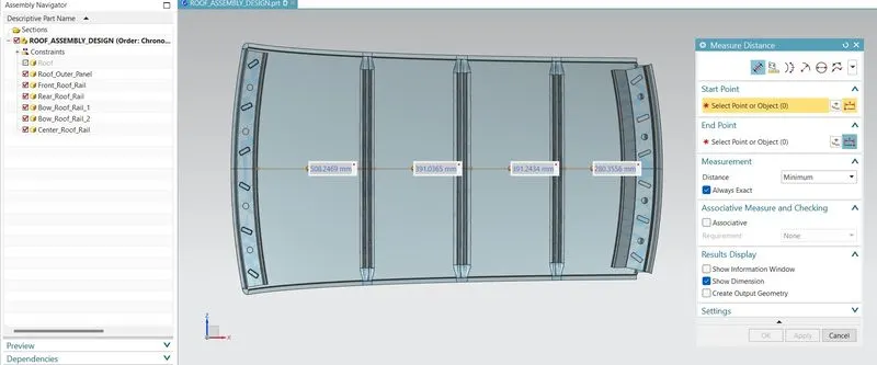
The edge to edge distance of the Front roof rail to Bow Roof Rail, Bow Roof Rail to Center Roof Rails , Center roof rails to Bow Roof Rails - 2, Bow Roof Rails - 2 to Rera Roof Rails Distance are been measured respectively.
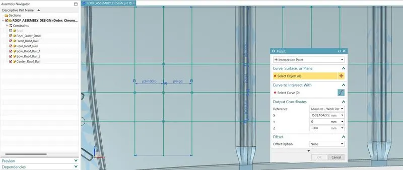
By creating Datum plane on the roof outer, the sketch has been drawn to create a Intersection point on the roof panel to determine a local raduis of curvature along x and y axis.
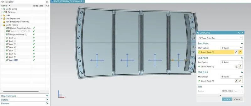
After creating the Intersection points on the plane, the points are been projected into the roof to calculet ethe Radius of curvature along x and y axis as Rx and Ry.
HEAT DISTORTION CRITERIA CALCULATION
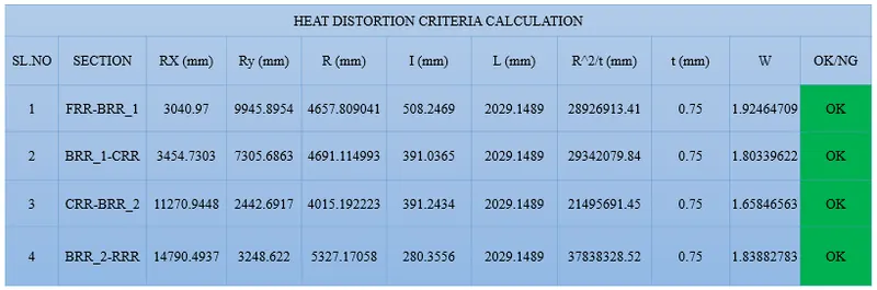
From the above tabulation it is obsorved that, the Heat distortion prediction, Bow roof position are been in good condition as per the judgement condition value < 2.7 mm.
The current Positioning of Bow roofs are correct.
(2). SNOW LOAD PREDICTION CALCULATION:
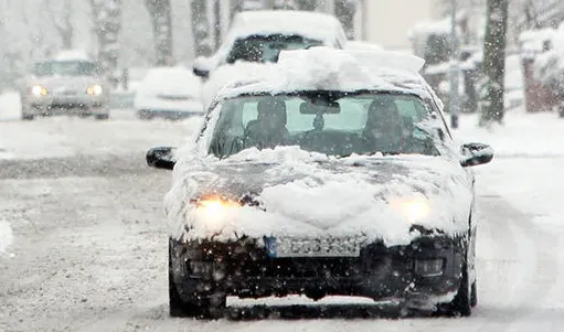
Snow load is a downward force acted on the roof. This criteria is useful to justify the bow roof position in snow fall regions. Roof must withstand the load as well as it should reflex back to its orignal position without any permanent deformation once the load is removed. The position of bow roof should be in a such a way that it should provide strength to the roof against bending.
FORMULA - SNOW LOAD PREDICTION;
`Qr = [I_y* t^2] / [α * s * [(R_x + R_y)/2]^2 * 10^-8]`
Where,
`α = M_y * L_x^2 * 10-12 , M_y = Y(L_y-Y)`
t = Roof plate thickness [mm]
Ly = Distance between the front and rear roof Rails on the Vehicle along with 0Y[mm]
Lx = Distance between the Left and Right end of the roof on the Roof BOW [mm]
Y = Distance front Front Roof Rail to Roof BOW[mm]
s = Distance for which Roof BOW bears divided load [mm]
`s = L_1/2 + L_2/2`
Iy = Geometrical moment of inertia of Roof BOW (Y cross-section )[mm4]
Rx = Lateral direction curvature radius of roof panel Y cross-section on Roof BOW [mm]
Ry = Longitudinal Direction curvature radius of the Roof panel X cross-section on Roof BOW [mm]
ROOF ASSEMBLY - SNOW LOAD PREDICTION:
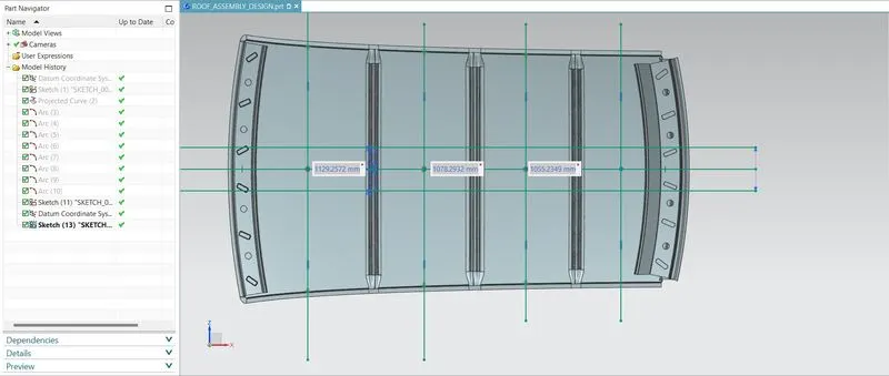
The center to center distance of the Front roof rail to Bow Roof Rail, Bow Roof Rail to Center Roof Rails , Center roof rails to Bow Roof Rails - 2, Bow Roof Rails - 2 to Rear Roof Rails Distance are been measured respectively.
By creating Datum plane on the roof outer, the sketch has been drawn to create a Intersection point on the roof panel to determine a local raduis of curvature along x and y axis.
After creating the Intersection points on the plane, the points are been projected into the roof to calculet ethe Radius of curvature along x and y axis as Rx and Ry.
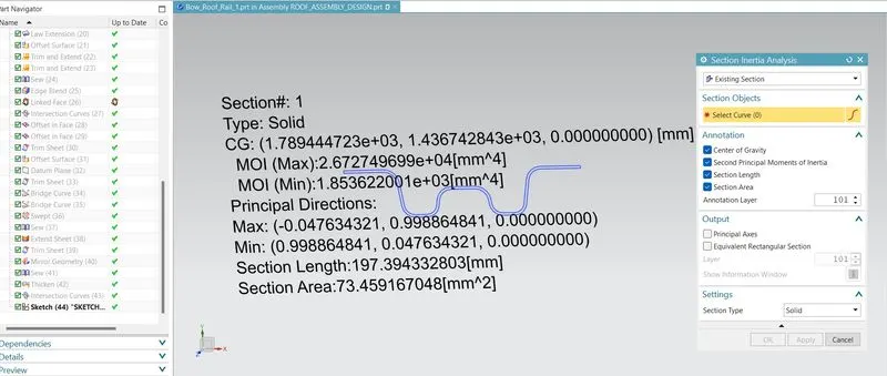
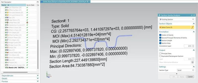
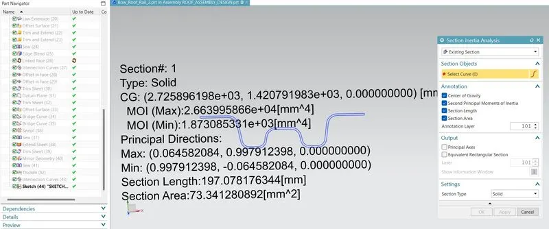
DETERMINING MOMENT OF INERTIA OF REINFORCEMNETS:
FRONT ROOF RAIL:

BOW ROOF RAIL - 1:
CENTER ROOF RAIL:
BOW ROOF RAIL -2 :
REAR ROOF RAIL - 2:
SNOW LOAD CRITERIA CALCULATION
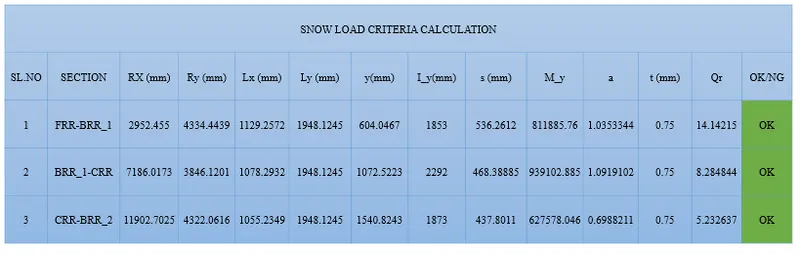
If Qr value is less than 3.1 then we need to improve the placement of bow roofs. In that case we can also suggest styling team to modify the curvature of surface. If it is not possible then we can improve the strength of the roof by creating the embosses on the surface of the outer panel of the roof.
For the current position of Bow Roofs and Center Roof Rails the condition is statisfied.
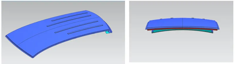
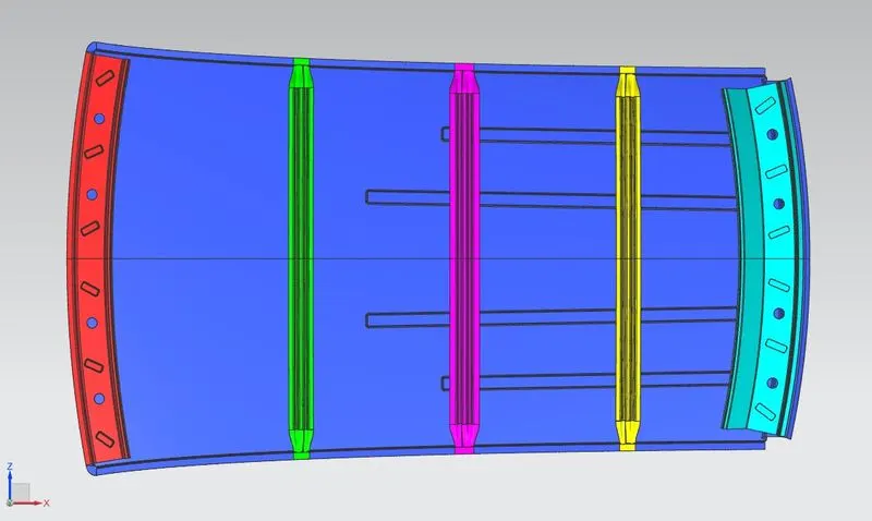
ROOF ASSEMBLY DESIGN VARIOUS ORIENTATIONS:
CONCLUSIONS:
- An Assembly for the Roof Outer by developing essential flanges are been created using the Stylish Roof surface.
- The Creation of Reinforcements by performing calculations for the position of Bow Roofs are calculates and determined.
- The draft on the Reinforcements and Roof Outer, Front Roof Rail, Rear Roof Rail, Center Roof rail and Bow Roof Rails are been analyzed.
- The curvature study on the Roof and Implement the remedies if position of criterion is Not fullfilling are been explained.
- The Roof Ditch Area with the tool opening angle of 7 degeree and the develoment of the Reinforcements (Front Roof Rail, Rear Roof Rail, Center Roof rail and Bow Roof Rails) as seperate Parts are been created
- The Front Roof Rail, Rear Roof Rail, Center Roof rail and Bow Roof Rails by following the Master sections are created.
- The Roof Assembly statisfying the Heat distortion and snow load conditions are been Calculated and determined as per the Judgement conditions.