ANALYSIS OF DESIGN TOOTH LOAD’S IN SPUR GEAR USING MATLAB
ANALYSIS OF DESIGN TOOTH LOAD’S IN SPUR GEAR USING MATLAB
AIM:
To analyze the different kind of load’s acting on the tooth of spur gear using Matlab and to validate the design loads are in satisfactory condition.
OBJECTIVE:
- To determine the Velocity ratio, Diametrical pitch of Gear and Pinion & Gear terminologies.
- To evaluate, the Dynamic, Tangential, Static and Wear tooth loads of spur gear using Lewis and Buckingham equation.
- To validate the design loads are in satisfactory conditions.
SCOPE IN DESIGN TOOTH ANALYSIS OF GEAR DRIVE:
- The gear teeth should have sufficient beam strength, so that they will not fail under static loading or dynamic loading during normal running conditions.
- The gear teeth should have wear characteristics so that their life is satisfactory.
- In order to determine those, design tooth analysis of spur gear are carried out.
INTRODUCTION:
GEAR DRIVE:
Gear drives, form a mechanical system used for transmitting shaft power from a driver such as an engine, turbine, or motor to a driven piece of machinery. Gear drives can alter the transmitted power by using different configurations of gears.
Gear drives can increase or decrease the rotational speed of the output shaft. By reducing the speed, when torque is increased. This force amplification characteristic is one of the main functions of speed reducers.
FILE PARSING:
Parsing a file means reading in a data file of some sort and building an in memory model of the semantic content of that data. Text files include a large amount of information including text and data that need to analyze. Often, need to sort through the file and identify particular data’s of information. It can be used to describe split or separation, In general, this is called file parsing.
In this project the PSG Design Data Book standard values are been parsed to execute the data’s which are required for the system of analysis. From the data using looping concept the data’s are retrieved and respective values are used in load analyzing.
SPUR GEAR:
Spur gears are the most extensively used gear type. They are cylindrical with straight teeth formed along the lateral surface of the cylinder. Spur gears can be external and internal.
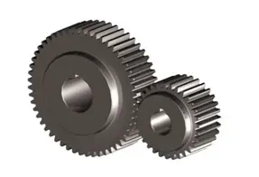
An external spur gear is considered the usual type that has teeth on its outside surface. An internal spur gear, is a hollow cylinder with teeth cut on its inner lateral surface.
TERMS USED IN GEAR:
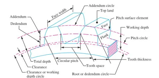
- Velocity Ratio - In precision machines, in which a definite velocity ratio is of importance. The effect of slipping is to reduce the velocity ratio of the system.
- Pitch circle diameter - It is the diameter of the pitch circle. The size of the gear is usually specified by the pitch circle diameter. It is also called as pitch diameter.
- Pressure angle or angle of obliquity - It is the angle between the common normal to two gear teeth at the point of contact and the common tangent at the pitch point. It is usually denoted by φ. The standard pressure angles are 14 1/2 ° and 20°.
- Addendum - It is the radial distance of a tooth from the pitch circle to the top of the tooth.
- Dedendum - It is the radial distance of a tooth from the pitch circle to the bottom of the tooth.
- Circular pitch. It is the distance measured on the circumference of the pitch circle from a point of one tooth to the corresponding point on the next tooth.
- Diametrical pitch - It is the ratio of number of teeth to the pitch circle diameter in millimeters.
- Face Width - It is the width of the gear tooth measured parallel to its axis.
- Module - It is the ratio of the pitch circle diameter in millimeters to the number of teeth. It is usually denoted by m.
Module, m = D / T
Where,
T = Number of teeth, and
D = Pitch circle diameter.
INVOLUTE GEARS:
- In involute gears is that the center distance for a pair of involute gears can be varied within limits without changing the velocity ratio.
- In involute gears, the pressure angle, from the start of the engagement of teeth to the end of the engagement, remains constant. It is necessary for smooth running and less wear of gears.
SYSTEMS OF GEAR TEETH:
The following four systems of gear teeth are commonly used in practice.
1. 14 1/2° Composite system.
2. 14 1/2° Full depth involute system.
3. 20° Full depth involute system, and
4. 20° Stub involute system.
The 14 1/2° composite system is used for general purpose gears. It is stronger but has no inter- changeability.
The tooth profile of the 14 1/2° full depth involute system was developed for use with gear hobs for spur and helical gears.
The tooth profile of the 20° full depth involute system may be cut by hobs. The increase of the pressure angle from 14 1/2° to 20° results in a stronger tooth, because the tooth acting as a beam is wider at the base. The 20° stub involute system has a strong tooth to take heavy loads.
GOVERNING EQUATIONS FOR TOOTH LOAD ANALYSIS:
- TANGENTIAL TOOTH LOAD (LEWI’S EQUATION):
W_t = (σ_p× C_v) *b*π *m*y_p
Where,
W_t - Tangential load acting at the tooth,
σ_p - Allowable static stress,
Cv - Velocity factor.
b – Face width
m – Module
y_p - Tooth form factor
- DYNAMIC TOOTH LOAD
The dynamic loads are due to the following reasons:
- Inaccuracies of tooth spacing,
- Irregularities in tooth profiles, and
- Deflections of teeth under load.
W_d = W_t + W_i
Where,
W_d = Total dynamic load,
W_t = Tangential load due to transmitted torque, and
W_i = Increment load due to dynamic action.
The increment load (WI) depends upon the pitch line velocity, the face width, material of the gears, the accuracy of cut and the tangential load. For average conditions, the dynamic load is determined by using the following Buckingham equation, i.e.
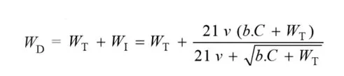
Where,
v = Pitch line velocity in m/s,
b = Face width of gears in mm, and
C = A deformation or dynamic factor in N/mm.
- STATIC TOOTH LOAD:
The static tooth load (also called beam strength or endurance strength of the tooth) is obtained by Lewis formula by substituting flexural endurance limit or elastic limit stress (σ_e) in place of permissible working stress (σ_w).
∴ Static tooth load or beam strength of the tooth,
W_s= σ_e*b*π* m*y
Where,
(σ_e) - Values of flexural endurance limit for different materials.
- WEAR TOOTH LOAD:
The maximum load that gear teeth can carry, without premature wear, depends upon the radii of curvature of the tooth profiles and on the elasticity and surface fatigue limits of the materials.
The maximum or the limiting load for satisfactory wear of gear teeth, is obtained by using the following Buckingham equation, i.e.
W _w= D_p*b*Q*K
Where,
W_w = Maximum or limiting load for wear in N,
D_p= Pitch circle diameter of the pinion in mm,
b = Face width of the pinion in mm,
Q = Ratio factor
K = Load-stress factor (also known as material combination factor) in N/mm2.
STEPS IN CODING:
STEP 1: Assigning the inputs of spur gear parameters using Input Dialog Box (Inputdlg).
STEP 2: Converting the strings into Numbers from the Input parameters.
STEP 3: Extracting the Data’s from PSG.txt file using fopen.
STEP 4: Using fgetl and for loop data are extracted to the respective parameters.
STEP 5: Selecting the required Involute teeth system using List Dialog Box (listdlg).
STEP 6: Selecting the desired Allowable static stress using List Dialog Box (listdlg).
STEP 7: Selecting the desired Endurance Limit using List Dialog Box (listdlg).
STEP 8: Selecting the desired Deformation factor using List Dialog Box (listdlg).
STEP 9: Selecting the desired Wear factor using List Dialog Box (listdlg).
STEP 10: Calling a function of the determined involute system, stress, Endurance limit, Deformation & Wear factor.
STEP 11: Evaluating different load’s acting on teeth in spur gear using Lewis and Buckingham equation.
STEP 12: Plotting the loads of dynamic loads with static and wear load.
STEP 13: Validating the loads are in satisfactory design conditions.
STEP 14: The estimated results are printed in command window.
METHODOLOGY:
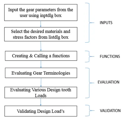
LOGIC EXPLANATION:
- To read the data of PSG DESIGN DATA.txt the file has been opened and read by using fopen command and the data's are stored in a variable to access file efficiently.
- Using for loop:
By, using the for loop the iterations of lines are skipped which are not significant and the significant data for evaluating are analyzed.
- using, [token,remain]=strtok()
The token returns the first leading variables and remain returns the remaining text, if any, in remain. If strtok finds a delimiter, then it is included at the start of remain. If strtok finds no delimiters in str, then it returns the whole of str, except for leading delimiters, in token, and remain has no characters.
- By using the strtok() the list and the values ranges are been identified.
- Then, using the for loop the required data’s for individual parameters are determined and the corresponding values are identified for all parameters.
- Creating functions to select and determine involute system, stress, Endurance limit, Deformation & Wear factor parameters.
- Also, to estimate the different load’s acting on the spur gear.
CODING:
CREATING FUNCTIONS:
% Creating function for calling an input parameters,
function[parameters]=gear_para(Input)
dlgtitle=('Gear Parameters');
dims=[1 25;1 25;1 50;1 50;1 50;];
parameters=inputdlg(Input,dlgtitle,dims);
end
% Creating Function for calling a Involute Teeth Profiles;
%Selection of Teeth profile system
function[T_pro]=Involute_teeth(list_1,value_1)
prompt={'Select Teeth Profile System'};
[sel]=listdlg('Promptstring',prompt,"ListString",list_1,"SelectionMode","single",'ListSize',[200 100]);
i=sel;
 switch i
    case {1}
        T_pro=value_1(1);  %14 deg Composite & Full depth
    case {2}
        T_pro=value_1(2);  %20 deg full depth
    case {3}
        T_pro=value_1(3);  % 20 deg stub
    otherwise
        T_pro=0;

 end
end
% Creating Function for calling a Deformation Factor;
function [c]=Deformation_factor(list_2,value_2)
prompt={'Select Material & profile system for Deformation factor'};
[c]=listdlg('Promptstring',prompt,"ListString",list_2,"SelectionMode","single",'ListSize',[300 180]);
n=c;
switch n
    case {1}
       c=value_2(1);
    case {2}
        c=value_2(2);
    case {3}
        c=value_2(3);
    case {4}
        c=value_2(4);
    case {5}
        c=value_2(5);
    case {6}
        c=value_2(6);
    case {7}
        c=value_2(7);
    case {8}
        c=value_2(8);
    case {9}
        c=value_2(9);
    otherwise
        c=0;

end
end
% Creating Function for calling an Endurance Limit;
%Selection of Gear material for fluxeral Endurance limit
function [en_s]=End_limit(list_3,value_3)
prompt={'Select Material for Endurance Limits'};
[en_s]=listdlg('Promptstring',prompt,"ListString",list_3,"SelectionMode","single",'ListSize',[200 100]);
n=en_s;
switch n
    case {1}
        en_s=value_3(1);
    case {2}
        en_s=value_3(2);
    case {3}
        en_s=value_3(3);
    case {4}
        en_s=value_3(4);
    otherwise
        en_s=0;
end
end
% Creating Function for calling an Allowable Static Stress;
%Selection of allowable static stress
function [st_stress]=static_stress(list_4,value_4)
prompt={'Select Material for Allowable static stress'};
[st_stress]=listdlg('Promptstring',prompt,"ListString",list_4,"SelectionMode","single",'ListSize',[250 200]);
n=st_stress;
switch n
    case {1}
        st_stress=value_4(1);
    case {2}
        st_stress=value_4(2);
    case {3}
        st_stress=value_4(3);
    case {4}
        st_stress=value_4(4);
    case {5}
        st_stress=value_4(5);
    case {6}
        st_stress=value_4(6);
    case {7}
        st_stress=value_4(7);
    case {8}
        st_stress=value_4(8);
    case {9}
        st_stress=value_4(9);
    case {10}
        st_stress=value_4(10);
    otherwise
        st_stress=0;

end
end
% Creating Function for calling an Wear factor;
%Selection of Load stress factor/ Wear factor
function[w_f]=wear_factor(list_5,value_5)
prompt={'Select Wear factor (k)'};
[w_f]=listdlg('Promptstring',prompt,"ListString",list_5,"SelectionMode","single",'ListSize',[200 100]);
i=w_f;
 switch i
    case {1}
        w_f=value_5(1);
    case {2}
        w_f=value_5(2);
    case {3}
        w_f=value_5(3);
    case {4}
        w_f=value_5(4);
    otherwise
        w_f=0;
 end
end
MAIN CODE:
%% DESIGNING OF SPUR GEAR TRAIN
%To Determine Different Design loads
%To validate Design tooth load's are safe or not
close all
clc
%% Inputting The Gear parameters
Input={'No.of.Teeth on Gear (T_g)','No.of.Teeth on Pinion (T_p)','Center Distance (l) in mm','Speed (n) in rpm','Gear Width (g_w) in mm'};
parameters=gear_para(Input);    % Calling a function for input parameters

%Converting input strings into numbers

T_g=str2double(parameters{1});
T_p=str2double(parameters{2});
l=str2double(parameters{3});
n_p=str2double(parameters{4});
g_w=str2double(parameters{5});

%% Extracting the Standared values of data's using PSG DATA book and it's nomenclature from PSG_DATA.txt file
a=fopen('PSG_DATA.txt','r'); % Data's are stored in a variable 'a'

%% Extracting the information of Header and Gear Notations using PSG DATA book
  for s=1:10
    fgetl(a); % Header Informations
  end
for i=11:13
[list1,value1]=strtok(fgetl(a));    % Returns Leading and remaining strings of Teeth profile
[list__1(i)]=(strsplit(list1));     % Splitting the strings into cells
[value__1(i)]=(str2double(value1)); % Converting strings into numbers
end
list_1=(list__1(11:13));            % Creating list for T_pro
value_1=(value__1(11:13));          % Creating respective values for T_pro

%% Extracting the information of Deformation factor
   for k=4:5
    fgetl(a); % Information for deformation factor
   end
for m=16:24
[list2,values2]=strtok(fgetl(a));  % Returns Leading and remaining strings
[list__2(m)]=strsplit(list2);      % Splitting the strings into cells
[value__2(m)]=str2double(values2); % Converting strings into numbers
end
list_2=(list__2(16:24));            % Creating list for c
value_2=(value__2(16:24));          % Creating respective values for c

%% Extracting the informations of Endurance limit
   for n=25:26
    fgetl(a); % Information for Endurance limit
   end
for q=27:30
[list3,values3]=strtok(fgetl(a));  % Returns Leading and remaining strings
[list__3(q)]=strsplit(list3);      % Splitting the strings into cells
[value__3(q)]=str2double(values3); % Converting strings into numbers
end
list_3=(list__3(27:30));           % Creating list for En_s
value_3=(value__3(27:30));         % Creating respective values for En_s
%% Extracting the informations of Allowable Static Stress
   for d=31:32
    fgetl(a); % Information for Allowable static stress
   end
for f=33:42
[list4,values4]=strtok(fgetl(a));  % Returns Leading and remaining strings
[list__4(f)]=strsplit(list4);      % Splitting the strings into cells
[value__4(f)]=str2double(values4); % Converting strings into numbers
end
list_4=(list__4(33:42));           % Creating list for s_p
value_4=(value__4(33:42));         % Creating respective values for s_p

%% Extracting the informations of Wear factor
   for j=43:44
    fgetl(a); % Information for Wear factor
   end
for o=45:48
[list5,values5]=strtok(fgetl(a));  % Returns Leading and remaining strings
[list__5(o)]=strsplit(list5);      % Splitting the strings into cells
[value__5(o)]=str2double(values5); % Converting strings into numbers
end
list_5=(list__5(45:48));           % Creating list for k
value_5=(value__5(45:48));         % Creating respective values for k

%% Calling a functions to get the parameters of gear
T_pro=Involute_teeth(list_1,value_1);   %calling a function for Involute profile
c=Deformation_factor(list_2,value_2);   %Calling a function for Deformation factor
en_s=End_limit(list_3,value_3);         %Calling a function for Endurance Limit
s_p=static_stress(list_4,value_4);      % Calling a function for Static Stress
k=wear_factor(list_5,value_5);          % Calling a function for Load stress factor

%% DETERMINATION OF DIFFERENT TOOTH LOAD'S

%Determining the gear ratio/velocity ratio
v_r=T_g/T_p; % Velocity Ratio

%Determining the pitch circle diameter of gear and pinion
% l=(d_g/2)+(d_p/2); ------- (1)   v_r=d_g/d_p ==> Velocity ratio is equal to pitch diameter of gear to pinion
% d_g=v_r*d_p  ------(2)  |converting the equations & substitute in (1)
% l=((v_r*d_p)+d_p)/2
%Solving the equations to find the pitch diameter of pinion

d_p=(2*l)/(v_r + 1);

%Then the pitch diameter of gear
d_g=v_r*d_p;

%Determining the module
m=d_g/T_g;

%Determine the face width
b=g_w*m;

%Determination of power transmitted by the gear | p=w_t*v
%Tangential tooth load of gear are calulated by using Lewie's equation |w_t=(sig_p*c_v)*b*pi*m*y_p

%Finding pitch line velocity
pitch_linevelocity=(pi*d_p*n_p)/60;

v=pitch_linevelocity/1000; % Unit conversion from mm to m.

% To find velocity factor
if v <=12.5       %Pitch line velocity <=12.5
     c_v=3/(3+v);
 elseif v <= 20   %Pitch line velocity <=20
     c_v=6/(6+v);
elseif v >=20     %Pitch line velocity >=20
     c_v=0.75/(0.75+sqrt(v));
end

%To find Lewis form factor/ Tooth form factor
if T_pro == 14           % for 14 degree composite & full depth involute system
    y=0.124-(0.684/T_p);
elseif T_pro == 20.0    % for 20 degree stub system
    y=0.175-(0.841/T_p);
elseif T_pro == 20       % for 20 degree full depth involute system
    y=0.154-(0.912/T_p);
end
%Tangential tooth load
w_t=s_p*c_v*b*pi*m*y;

%Power transmitted
p=w_t*v;

%Determination of dynamic tooth load  | w_d=w_t+w_i
%To determine incremental load due to dynamic action
w_i=(21*v*((b*c)+w_t))/((21*v)+(sqrt((b*c)+w_t)));

w_d=w_t+w_i;  %Dynamic tooth load

%Design static tooth load By applying Lewi's Equation,
w_s=en_s*b*pi*m*y;

%Design Wear tooth load  | W_w=d_p*b*Q*k
%To determine the ratio factor
Q=(2*v_r)/(v_r+1);

W_w=d_p*b*Q*k; %Wear Tooth load


%% PLOTTING;
%Data points for plotting
Dynamic_tooth_load=linspace(0,w_d,2);
Static_tooth_load=linspace(0,w_s,2);
Wear_tooth_load=linspace(0,W_w,2);

% PLOTTING OF DYNAMIC TOOTH LOAD vs STATIC TOOTH LOAD
figure(1)
plot(Dynamic_tooth_load,Static_tooth_load,'g','linewidth',1)
hold on
plot(w_d,w_s,'o','markersize',10,'markerfacecolor',[1 0.5 0],'markeredgecolor',[1 1 1])
grid on
xlabel('DYNAMIC LOAD (N)')
ylabel('STATIC LOAD (N)')
title({'LOAD COMPARISION';'Dynamic Load vs Static Load'})
legend('Data Point','Max Load Point','Location','northwest')
% legend('boxoff')
set(gca,'FontSize',12)

% PLOTTING FOR DYNAMIC TOOTH LOAD vs WEAR OOTH LOAD
figure(2)
plot(Dynamic_tooth_load,Wear_tooth_load,'b','linewidth',1)
hold on
plot(w_d,W_w,'o','markersize',10,'markerfacecolor',[1 0.5 0],'markeredgecolor',[1 1 1])
grid on
xlabel('DYNAMIC LOAD (N)')
ylabel('WEAR LOAD (N)')
title({'LOAD COMPARISION';'Dynamic Load vs Wear Load'})
axis([0 w_d+2000,0 W_w+10000])
legend('Data Point','Max Load Point','Location','northwest')
% legend('boxoff')
set(gca,'FontSize',12)

%% DESIGN TOOTH LOAD ANALYSIS RESULTS;

fprintf('           DESIGN ANALYSIS OF SPUR GEAR USING MATLABn')
fprintf('TERMINOLOGIES IN SPUR GEAR: n')
fprintf('         Velocity Ratio (V_R): =%.3f n',v_r)
fprintf('Pitch Diameter of Pinion(D_g): =%.3f mmn',d_p)
fprintf(' Pitch Diameter of Gear (D_p): =%.3f mmn',d_g)
fprintf('                   Module (m): =%.3f mm n',m)
fprintf('               Face Width (b): =%.3f mmn',b)
fprintf('          Pitch Line Velocity: =%.3f m/s n',v)
fprintf('     Power To Be Transmitted : =%.3f Wattsn',p)

fprintf('GEAR TOOTH LOADS: n')

fprintf('   Tangential Tooth Load: =%.3f Nn',w_t)
fprintf('   Dynamic Tooth Load:    =%.3f N n',w_d)
fprintf('   Static Tooth Load:     =%.3f N n',w_s)
fprintf('   Wear Tooth Load:       =%.3f Nn',W_w)

fprintf('Based On the Parameters & Design Tooth Loadsn')
if w_s>w_d
   fprintf('Maximum Static Load Is Grater Than Dynamic Load - (w_s>w_d) n')
   fprintf('%% The Design is Safe %% n')
else
    fprintf('Maximum Static Load Is less Than Dynamic Load - (w_s<w_d)n')
    fprintf('Design Parameters Are Not Stasisfactoryn')
end

if W_w>w_d
   fprintf('Maximum Wear Load Is Grater Than Dynamic Load - (W_w>w_d)n')
   fprintf('%% The Design is Safe %% n')
else
    fprintf('Maximum Wear Load Is Grater Than Dynamic Load - (W_w<w_d)n')
    fprintf('Design Parameters Are Not Stasisfactoryn')
end
LOGICS & CODING EXPLANATIONS:
- Assigning the input parameter for the spur gear using input dialog box.
- Creating a function for Input dialog box using inputdlg command and specified dimensions and tittles.
- Calling a function to get data from the input dialog box by the respective function name.
- The inputs from the user are converted into numbers using str2double command and the respective values are stored in the respective cells.
- Then, extracting the data’s from PSG data.txt file using fopen
- The data are in readable format using fopen and r commands and stored in the specified variable.
- Extracting the information of header and gear notions using fgetl command and the significant and insignificant a values are been segregated using for loop.
- Using for loop the header information’s are extracted.
- By using the strtok() the list and the values ranges are been identified.
- Then, using the for loop the required data’s for individual parameters are determined and the corresponding values are identified for all parameters.
- The extracted values are converted into number using str2double command.
- The same procedure are followed for all the data extraction process to extract, Involute teeth profile’s, Deformation factor, Endurance limit, Allowable static stress and wear factors.
- Creating a function and by calling the respective functions the desired data’s for Involute teeth profile’s, Deformation factor, Endurance limit, Allowable static stress and wear factors are been determined.
- In the function, the respective values are determined by using the Switch case otherwise
- Then, determining the different load condition’s using Lewis and Buckingham equation.
- The Velocity ratio, Diametrical pitch for gear and pinion, Module, Face width, Pitch line velocity, and Lewis form factors are determined in order to evaluate the design tooth load’s.
- The velocity factor is depending on the different velocity conditions based on the conditions using if else statement the respective velocity factors are determined.
- Then, the Lewis form factor are also based on teeth profile conditions based on the conditions using if else statement the respective factors are determined.
- After the determination and extracting of all the parameters the Dynamic load, Tangential load, Static tooth load and wear tooth load are been determined.
- Based on the determination of those load’s the plotting has been done.
- The data points are extracted using linspace
- In figure(1), the plotting for Dynamic and static tooth load are plotted.
- In figure(2), the plotting for Dynamic and wear toot load are plotted.
- By the determination of data for design tooth load analysis of spur gear the validation and results are generated using fprintf command and validation of design load’s are done using if else statement.
- The design parameters satisfactory conditions are executed in the command window.
PLOTTING:
- LOAD COMPARISION FOR DYNAMIC AND STATIC TOOTH LOAD:
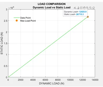
- From the plot it is observed that the static load is grater then the dynamic load.
- The static tooth load (also called beam strength or endurance strength of the tooth) is obtained by Lewis formula by substituting flexural endurance limit or elastic limit stress (σ_e) in place of permissible working stress (σ_w).
- The gear teeth should have sufficient beam strength, so that they will not fail under static loading during normal running conditions.
- Based on the analysis, the static load has the maximum load then dynamic loading.
- The design load are in satisfactory conditions.
PLOTTING:
- LOAD COMPARISION FOR DYNAMIC AND WEAR TOOTH LOAD:
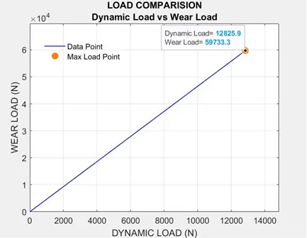
- From the plot it is observed that the wear load is grater then the dynamic load.
- The maximum load that gear teeth can carry, without premature wear, depends upon the radii of curvature of the tooth profiles and on the elasticity and surface fatigue limits of the materials.
- The maximum or the limiting load for satisfactory wear of gear teeth, is obtained by using the following Buckingham equation.
- The gear teeth should have sufficient beam strength, so that they will not fail under wear or surface loading during normal running conditions.
- Based on the analysis, the wear load has the maximum load then dynamic loading.
- The design load are in satisfactory conditions.
RESULTS:
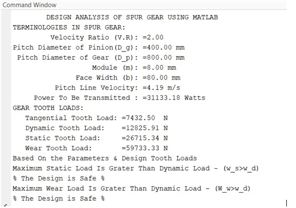
CONCLUSION:
- The Velocity ratio, Diametrical pitch of Gear and Pinion & Gear terminologies are determined.
- The Dynamic, Tangential, Static and Wear tooth loads of spur gear using Lewis and Buckingham equation are evaluated.
- The sufficient beam strength, gear teeth should not fail under static loading or dynamic loading during normal running conditions are determined and validated.
- The gear teeth wear characteristics are determined to estimate their life is satisfactory.
- The validation for design loads are in satisfactory conditions are been carried out.
REFERENCE: