SIMULINK MATHEMATICAL MODEL & SUSPENSION SYSTEM COMPARISION
AIM:
To plot the Mathematical Equation model using Simulink Blocks and to study the suspension system comparision.
OBJECTIVE:
- Plot a function y(x) = (x-1) * (x-3)^2 * (x-9)^2 using Simulink blocks.
- To Study ''SUSPENSION SYSTEM COMPARISION.
A. The similarities and differences between the three systems of suspensions, and the objective of simulation.
B. Observations from the results
C. Creating the oscillating velocity source.
INTRODUCTION:
MATHEMATICAL MODEL:
A mathematical model is a representation of a physical system. Models are represented graphically in a Simulink as block diagrams. Simulink is able to numerically approximate the solutions to mathematical models.
SIMULINK OF MATHEMATICAL EQUATION:
The blocks used in Simulation & Explanations are;
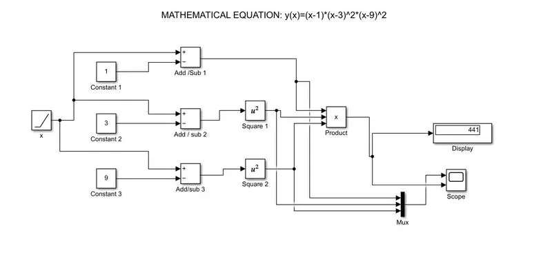
- Ramp Block - The ramp block is used as a variable 'x' in which it generates a signal that starts at a specified time and value changes by a specified rate. The block's Slope, Start time, and Initial output parameters determine the characteristics of the output signal.
- Constant Block - The constant block is used to generates a real or complex constant value signal. By using this block to provide a constant signal input. In this three constant values are induced as (-1),(-3) & (-9)
- Add Block - The add block performs addition or subtraction on its inputs. This block can add or subtract scalar, vector, or matrix inputs. By using the parameter with plus (
+), minus (-), and spacer (|). The number of+and-characters equals the number of inputs. In this three operations are performed (x-1), (x-3), (x-9) as input parameters from constant block and ramp block. - Square Block - The square mathematical block is used to square the required functions and also it performs logarithmic, exponential, power and modulus functions.In this the two functions are squared (x-3) & (x-9) after performing the addition/subtraction block.
- Product Block - It performs scalar or matrix multiplication. The block accepts one or more inputs, depending on the number of input parameter. The Number of inputs parameter also specifies the operation to perform on each input. In this the functions are multiplied as (x-1)*(x-3)^2*(x-9)^2
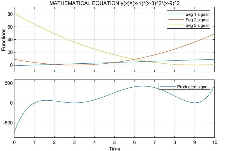
- Scope Block - Scope block display time domain signals, the scope displays simulation results for attached input signals. In the matematical model with the time domain the stop time are setted as 10 sec. The input ramp block, x variable takes 10 as input and based on the specified rate the values changes according to resultant value.
- Display Block - The Display block shows the value/ Result of the input data. The total producted value displayed
- Mux Block - It combines inputs with the same data type. The output mux signal is flat, even to create the mux signal from other mux signals. A mux signal simplifies the visual appearance of a model by combining two or more signal lines into one line. Mux signals do not affect simulation. In this the function operations are exected using Mux block with scope the graphically display's the results of the functional operational signal and the resulted signal as product.
SIMULINK MATHEMATICAL MODEL:
OUTPUT:
LINK OF MODEL: https://drive.google.com/file/d/11sEMrziNMnqQ4qQmwgkEyR-YFQeCd4sS/view?usp=sharing
SUSPENSION SYSTEM COMPARISION:
SUSPENSION SYSTEM:
Suspension is the mechanical system of springs or shock absorbers and linkages that connecting the wheels and axles to the chassis of a wheeled vehicle and allows relative motion. It is important for the suspension to keep the road wheel in contact with the road surface as much as possible, because all the road or ground forces acting on the vehicle do so through the contact patches of the tires.
OBJECTIVE OF SIMULATION:
- To Analyze the model of a testbed containing three sets of springs and dampers excited by the same oscillating velocity source.
- Developing the ideal transilational velocity source to simulate.
- The position of the un-sprung masses in three different stiffeness spring models that are subjected to the same oscillating velocity source.
- The position of the sprung masses in three different suspension models that are subjected to the same oscillating velocity source.
- To Execute the Spectrum Analyzer block as the scope, displays the frequency spectra of signals.
THE THREE SYSTEMS ARE:
- Shock Absorber
- Non-linear Spring
- Linear spring
SHOCK ABSORBER:
A shock absorber or damper is a mechanical or hydraulic device designed to absorb and damp shock impulses. It converting the kinetic energy of the shock into another form of energy as heat which is then dissipated. In a vehicle, shock absorbers reduce the effect of traveling over rough ground, leading to improved ride quality. While shock absorbers serve the purpose of limiting excessive suspension movement, their intended sole purpose is to damp spring oscillations.
Shock absorbers use valving of oil and gasses to absorb excess energy from the springs. Effective wheel bounce damping may require tuning shocks to an optimal resistance.

The Shock Absorber block represents a spring-damper system commonly used to dampen vibration in mechanical systems. An internal force acts between ports R and C. This force is the sum of spring stiffness, damping.
NON-LINEAR SPRING:
Non-linear springs are helical coil springs that exert an inconsistent amount of force as it is under a working load or torque.

The Nonlinear Translational Spring block represents a translational spring with a nonlinear force-displacement curve. The spring force magnitude is a general function of displacement.
VARIABLE SPRING:
The Variable Translational Spring block represents a translational spring with variable stiffness. A physical signal input port provides the variable spring stiffness. The magnitude of the spring force is equal to the product of the physical signal input and the relative linear displacement between the two translational conserving ports.

In the port k the variable stiffness and critical damping are provided. The sign of the spring force acting on port R is equal to the sign of the relative linear displacement between the two ports. A positive linear velocity corresponds to a positive spring force acting on port R, and a negative spring force of equal magnitude acting on port C.
STIFFNESS:
Stiffness is the rigidness of any object or material. Objects with a high stiffness will resist changes in shape when being acted on by a physical force. Stiffness is the resistance of an elastic body to deflection or deformation by an applied force.
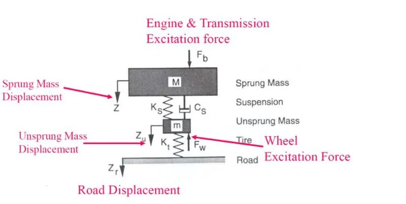
UNSPRUNG MASS:
The weight of the wheels, tyres, brakes are considered to be the unsprung mass of a vehicle which is defined as the mass between the road and the suspension.
SPRUNG MASS:
The weight of the engine, transmission, various mechanical and electrical components, passenger cabin, passengers and various other components whose weight is supported by the suspension of a car in total is called sprung mass.
SIMILARITIES IN THREE SYSTEMS:
- The same oscillating velocity source is given for all the three suspension systems.

The Ideal Translational Velocity Source block represents an ideal source of velocity that generates velocity differential at its terminals proportional to the input physical signal.Connections R and C are mechanical translational conserving ports. Port S is a physical signal port, through which the control signal that drives the source is applied.
- The unsprung mass is connected to the bottom of the suspension are same in all three systems.
- The Sprung mass is the load sitting on top of the springs is similar in all three systems.

In the sprung and unsprung mass the Ideal Force Source are used to represents an ideal source of mechanical energy that generates force proportional to the input physical signal. That signal is created by using ps constant block and the masses are added with sprung and unsprung forces.
DIFFERENCE IN THREE SYSTEMS:
- The first system uses the Shock Absorber block and includes linear stiffness and damping. Optional friction and hard stops are not used.
- The second shock absorber uses a Nonlinear Translational Spring and a Nonlinear Translational Damper specified by symmetric polynomials.
- The third system uses a Variable Translational Spring and Variable Translational Damper.
OBSERVATIONS FROM THE RESULTS:
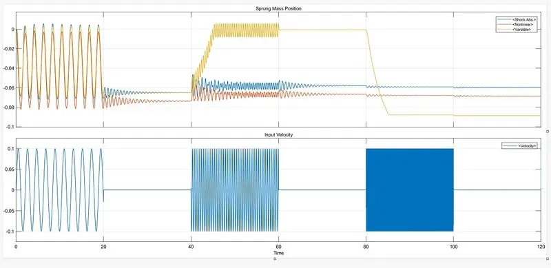
- The same oscillating velocity source is equally distributed to the three systems as an input.
- In shock absorber while oscillating velocity source is created the damping is done that reduces the vibration. The linear stiffness of unsprung mass also reduce the vibration by the application of shock absorber. The shock absorbers reduce and slow down the vibrations from the springs and attains it's equilibrium position of sprung mass. This involves the flow of oil being slowed down by the valve passages inside the damper. Optional friction and hard stops are not used.
- The second shock absorber uses a Nonlinear Translational Spring and a Nonlinear Translational Damper specified by symmetric polynomials. In which the created vibration due to oscillating source makes the displacement lesser due to that springs consit of helical coils that exert an inconsistent amount of force and it absorb the vibrational energies and attains it's equilibrium position of sprung mass.
- The velocity source is applied to variable transilational spring with variable stifness where the displacements are varied according to the variable time constraints and attains it's equilibrium position of sprung mass.
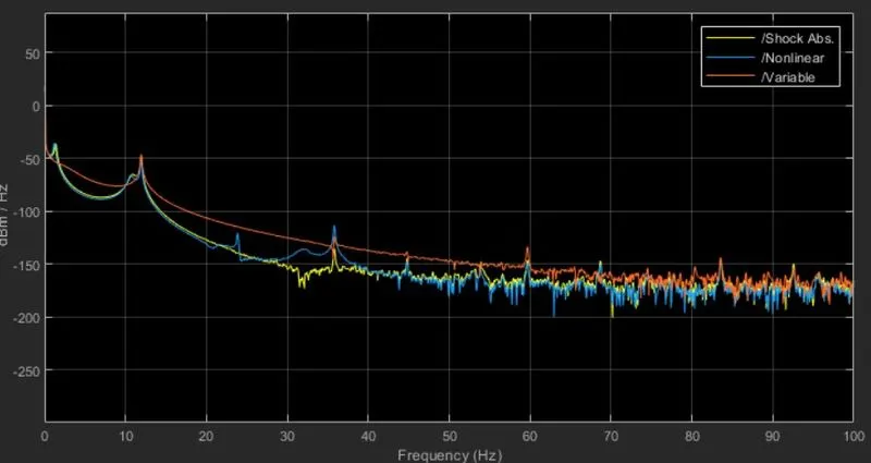
From the specturm analyzer it is absorbed that,
- The shock absorber creates linear displacement with the duration of time. The shock absorber reduse the vibration from the input oscillating velocity.
- Also the shock absorber with non linear spring and non linear stiffeness it creates lesser displacement with the duration of time and attains it's equilibrium position of sprung mass.
- The variable spring uses variable stiffness spring due to this, the eqilibrium position to attain the sprung mass take time duration higher also it makes the sudden displacements in certain time constraints.Then only it attains it's equilibrium position.
CREATING OSCILLATING VELOCITY SOURCE:
- The oscillating velocity source is created by using,
(1) Sine wave
(2) Pulse generator
Sine wave:
The Sine Wave block outputs a sinusoidal waveform. The block can operate in time-based or sample-based mode.

By differing the Amplitude and frequency the different sinusoidal wave's are created.
Pulse generator:
The Pulse Generator block generates square wave pulses at regular intervals. The block waveform parameters, Amplitude, Pulse Width, Period, and Phase delay, determine the shape of the output waveform.

By differing the Amplitude, Pulse Width, Period, and Phase delay the different square wave pulses are generated.
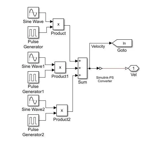
- Then, the both signals from the sine wave and pulse generator are multiplied and add up the simulink signals are created.
- The simulink signals are converted into physical signals by using Simulink -PS converter. Then the signales are connected to physical model connection port. The Connection Port block transfers a physical connection or signal across subsystem boundarie.
- Then the signals are transferred to goto port to pass the signal to from port. from which te signals are passed to ideal velocity source.
CONCLUSION:
- The Plots are created for the function y(x) = (x-1) * (x-3)^2 * (x-9)^2 by basic Simulink blocks.
- The “Suspension System Comparison” are studied from which the shock absorber dampers the vibration within the duration of time. so, compared to other two systems the shock absorber with linear stiffness and damping creates lesser displacement and attains it's equilibrium sprung position.
- The oscillating velocity source is created using sine wave and pulse generator.
REFERENCE: