Fender Design - Wheel Arch Challenge
FENDER DESIGN - WHEEL ARCH
AIM:
To calculate the Wheel Arch gap between the Fender Arch to the Wheel at required points and also to check whether the Wheel arch Model statisfy the European Standard.
OBJECTIVE:
- To calculate the wheel Arch Gap between the Wheel and fender Outermost Curve.
- To Check whether the Fender Wheel Arch Model should statisfy the European Regulations as per the Standard.
INTRODUCTION:
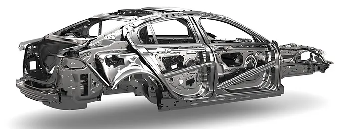
BODY IN WHITE (BIW):
In the Automotive Industry BIW (Body in White) is the common terminology used to mention the car sheet metal welded structure (body shell). Sub-assemblies like Under body, Body side Left Hand Side/ Right Hand Side, Front End, Roof etc. gets welded together by various metal joining process like resistance spot welding, Laser welding, MIG welding to make welded metal shell (Without Door, Trunk-lid / Tailgate) , Fender, Hood) called Body in White. Automotive car shell made before painting is called Body in White.
FENDER :
Fender is a plastic, metal, or rubber curved panel over the wheels on the side of a car, extending from the front bumper of the car to the door. The main purpose of fenders is to keep dirt, mud, and other debris off of the tires and braking system, making them safer and more efficient.
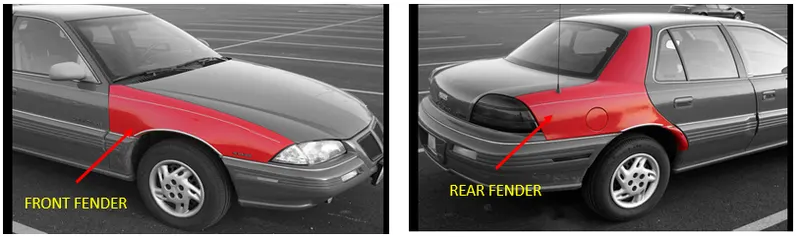
Fenders are attached to the frame of the car, and they come in different styles and sizes.Fenders also help prevent mud, dirt, dust particles, and other liquids from getting thrown in the air while the tires rotate.
STANDARD REGULATIONS FENDER WHEEL ARCH DESIGN
JAPANES STANDARD REGULATION:
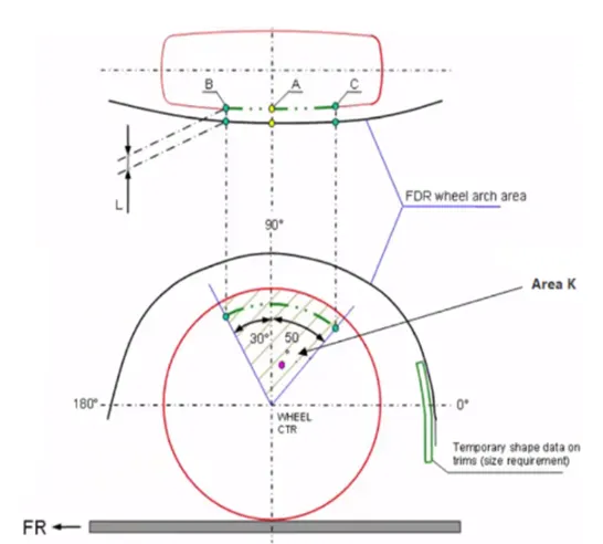
- According to the Japnese Regulations, the Fender - wheel arch has been calculated at the Marked sections at "K".
- The Distance between the Fender Outermost curve and the Wheel surface are been denoted as "L".
- Based on the Japnese Regulation, from the center line the Horizontal line from 0 to 180 deg has been drawn and vertical line Perpendicular section are been drawn as Wheel center Reference.
- From the Neutral line (Vertical Axis), the section are 30 deg rearward and the section 50 deg forward.
- The value of "L" Should be grater than 5.00 mm .
- The clearence value "a" Wheel Guard Requirement should be grtaer than 5.00 mm to meet the Japnese Regulations.
US STANDARD REGULATIONS:
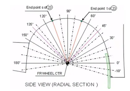
- According to the US Regulations, the Fender - wheel arch has been calculated at the each Respective Angels as per the standard Regulations.
- The Distance between the Fender Outermost curve and the Wheel surface are been denoted as "L".
- From the Neutral line (Vertical Axis), the section are created at each 10 degs rearward and the sections are created upto -20 deg forward.
- The value of "L" Should be grater than 5.00 mm .
- The clearence value "a" Wheel Guard Requirement should be grtaer than 5.00 mm to meet the US Regulations.
EUROPEAN STANDARD REGULATIONS:
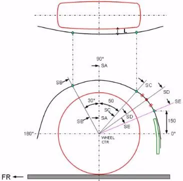
- According to the European Regulations, the Fender - wheel arch has been calculated at the different sections SA, SB,SC,SD,SE respectively.
- The Distance between the Fender Outermost curve and the Wheel surface are been denoted as "L".
- Based on the European Regulation, from the center line the Horizontal line from 0 to 180 deg has been drawn and vertical line section are denoted as "SA" Perpendicular section are been drawn as Wheel center Reference..
- From the Neutral line (Vertical Axis), the section "SB" are 30 deg rearward and the section "SC" 50 deg forward and the section "SE" are 150 mm from the Horizontal line.
- Using the Derived line command to create the Bisecting line between the sections "SC" and "SE".
REQUIREMENTS:
- The Clearence value "L" at all the intersection points (Five Points) should be grater tan 10 mm to statify the european standard.
- The Value of "a" should be grater than 5 mm at the intersection point from the wheel outermost part to the Fender outermost curve.
WHEEL ARCH - CALCULATIONS:
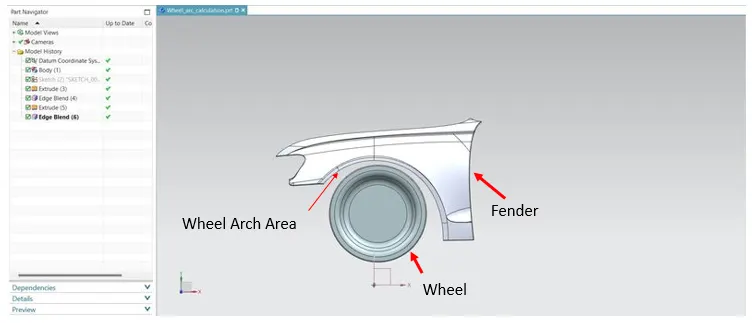
From the Given Model Fender Wheel Arch, Need to calculate as per European Regulations standard, whether this meet the all standard values are not.
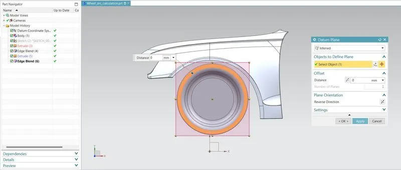
By using the Datum plane commad, the object @ the wheel outer surfaces are selected as Inferred by which the plane are been created.
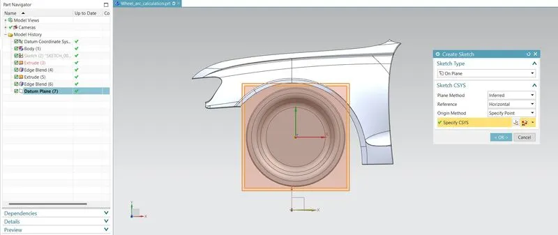
After defining the plane on the Wheel area, the sketch has been created on the plane using the origin method as Specify points.
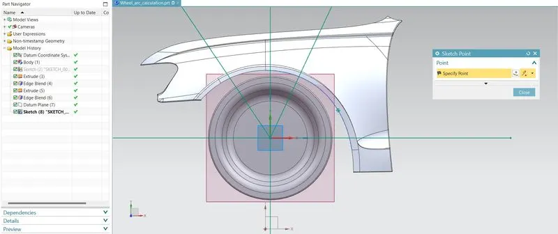
By using the line and point in the sketch tools, from the cebter point 0 to 90 deg line has been draw and also 0 to 180 deg line has been drawn. By using the point Infered, point is created on the Fender Outermost arch.
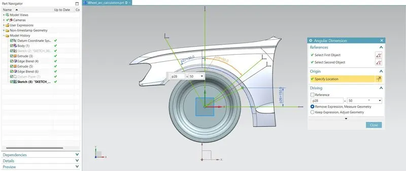
By using the Rapid and Angular Dimensions, from the perpendicular line 30 deg rearward line has been drawn as section SB and 50 deg forward line has been drawn as section SC.
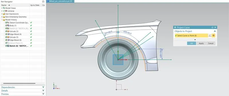
By using the Project curve option from the Sketch tools, the Fender outermost curve as been selected.
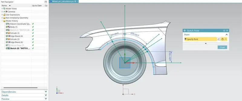
By using the point command, intersection between the line and outermost curve for the 5 Sections are been created.
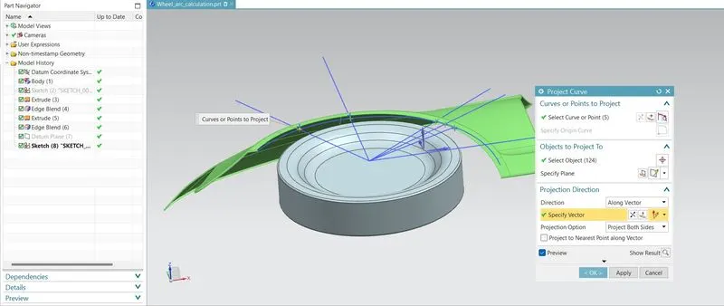
By using the project curve comand, the points are been selected and projected on both sides along the vector Z Axis.
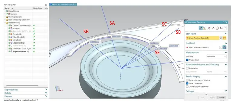
By using the Measure tool the distance between the Projected point to the fender curve are been Measured.
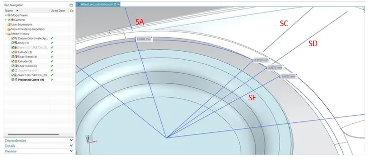
The clearence between the sections @ SA, SC,SD,SE, the value of "L" will not meet the European Regulation Standardas 10 mm which are below 10 mm.
RESULT TABULATION:
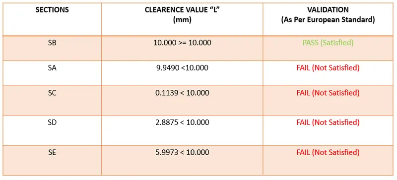
From the Tabulation listed for different sections obtained clearence values, from which the section @ SB only statisfied the European standard, other than that all the other sections are Not Statisfied (Negative Values).
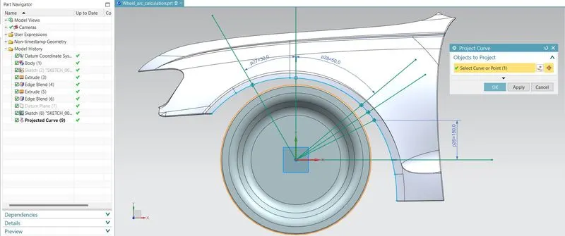
By using the Project curve from the sketch tools, the Wheel outermost curve are been selected on the respective plane.
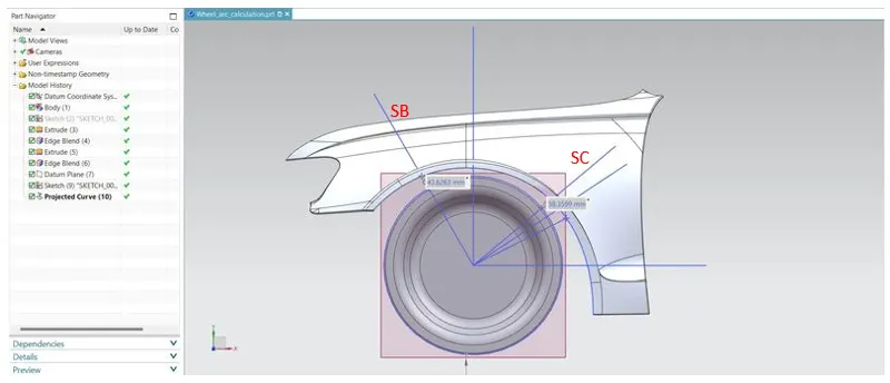
After projecting the Wheel outermost curve, using the intersection point the curve and the line are been selected to cretae intersection points from which the clearence values "a" are been measured using the Measure tool.
RESULT TABULATION:
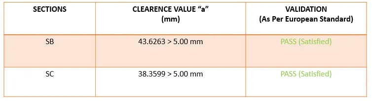
From the Above tabulation, the clearence between the wheel outermost curve to the Fender arch outermost curve are found to be more than 5 mm which statisfies the European standard.
WHEEL ARECH AREA:
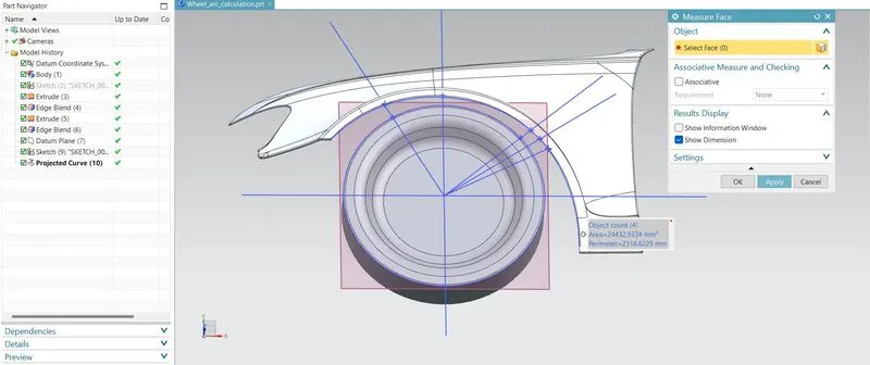
By using the Measure tool, the area @ the Fender Arch area are been measured as 24432.9334 mm^2.
CONCLUSION:
- The wheel Arch Gap between the Wheel and fender Outermost Curve are been calculated at 5 different sections and found to be valid @ one section only at Section "SB".
- The Reamining Sections are found to be Not statisfied with the European standard which are obsorved as less than 10.00 mm at the sections "SA","SC","SD","SE".
- The clearence value "a" from the wheel outermost curve to the fender curve are found to be statisfied as per the European standard as grater than 5.00 mm at sections "SB" and "SC"
- From the above observations, it is concluded that the Fender Wheel Arch Model is Not statisfied with the European Regulations as per the Standard.
- The Fender Model No meeting the European Regulation standards.
- The stylish of the Fender Design should Improve Curvature of the curve of Fender at sections SA,SC,SD,SE respectively to meet the european standard as grater than 10.00 mm.