Week - 4
MODELLING OF WASHING MACHINE USING STATE FLOW
AIM:
To implement control logic of a “washing machine” using State flow as per the sequences.
OBJECTIVE:
- To implement the state machines using control logics for the sequence.
- To create a power supply for activating the systems.
- To indicate through LED, if water supply is not available.
- To turn ON LED after completion of processes.
CONDITIONS:
- Soaking time = 200 sec
- Washing time = 100 sec
- Rinsing time = 20 sec
- Drying time = 50 sec
INTRODUCTION:
STATE FLOW:
Stateflow provides a graphical language that includes state transition diagrams, flow charts, state transition tables, and truth tables. Simulink models react to input signals, events, and time-based conditions based on control logics.
Stateflow enables to design and develop supervisory control, task scheduling, fault management, communication protocols, user interfaces, and hybrid systems. Graphical animation enables to analyze and debug a logics while it is executing. Edit-time and run-time checks ensure design consistency and completeness before implementation.
PROCESS IN WASHING MACHINE:
The Washing machine is mostly applied to machines that use water as opposed to dry cleaning (which uses alternative cleaning fluids) or ultrosonic cleaners. The following are the processes in which washing operations are to be carried out,
SOAKING - The soaking is a process in which the clothes/ things are to be soaked at the certain time from the water supply and then washing of clothes occurs.
WASHING - Processes of cleaning something in water with some sort of soap or detergent.
RINSING - Process that after have finished the washing part, put the things in fresh plain water till the residue of the cleaning process is completely gone, and the last water to use is clean because the garment, for instance no longer has any residue left in it.
DRYING - It is the process in after the rising process. After removel of residuals from the cloths the drying operation performs to dry the clothes.
COMPONENTS USED IN MODELLING:
- Constant
- State flow chart
- States
- Transitions
- Junction
- Display
- Rocker switch
- Lamp
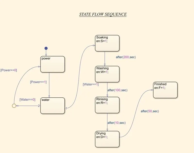
STATE FLOW OF WASHING MACHINE:
INPUTS AND OUTPUT PORT:
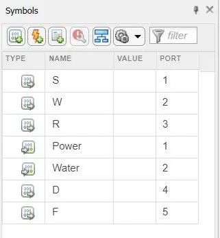
- The input and output parameters are assigned to the variables in state logic's. The water supply and power switch are assigned as input parameters.
- The soaking, washing, rinising, drying operations are output process.
CONTROL LOGICS AND EXPLANATIONS IN WASHING MACHINE:
- As per the given sequence the power has been supplied to activate the system. The acivation is controlled by the rocker switch system ON -1 and OFF-0. If the power is activated the Lamp is turn On to green color.
- Then, water supply is provided followed by the power supply. If water supply is activated the Lamp indicates as green colour
- If the water supply fails means the power transitions are also fail in the system and lamp turns into RED colour.
- Then, the Soaking operation is performed from the water spply at the time for 200 seconds. After the soaking process lamp indicates green colour.
- Followed by the soaking process, Washing process takes place to wash the clothes for 100 seconds. After the washing process lamp indicates green colour.
- Then, Rinsing process takes place to remove the residue from the clothes and the water comes out from the system, the process continues as a certian loop to remove the residues in the clothes. Rinsing process activated for 20 seconds in the system. After the rinsing process lamp indicates green colour.
- After rinsing process, Drying process are to be carried out to dry the clothes at a time of 50 seconds. After all the processes have completed, the finished LED is turns ON state.
SIMULINK MODEL OF WASHING MACHINE:
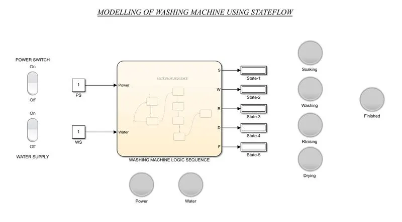
- The modelling of Washing machine consist of the activating rocker switch in which the activation ON denoted as 1 and deactivated as 0. The power switch and the water supply are connected with the respective swithes.
- Then the signals are transferred as input to state logics in which the sequence of operations are performed.
DIFFERENT STATES:
- If power supply is turned on and water supply fails,
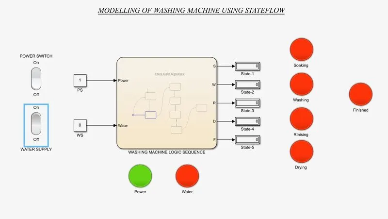
- If the power switch is activated and the water supply is deactivated the indicators indicates RED in colour.
- The logic is not executed and the power gets turned OFF.
2. If power and water supply is activated, Soaking process activated:
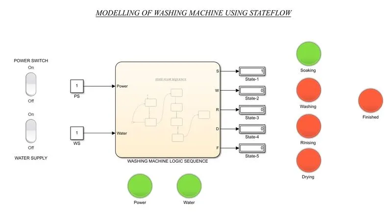
- If the power supply and the water supply is activated as shown in the GREEN colour indicator.
- The supply is gets activated, then the soaking process is activated and process is take time for 200 seconds as per conditions.
4. After Soaking process, Washing Process activated:
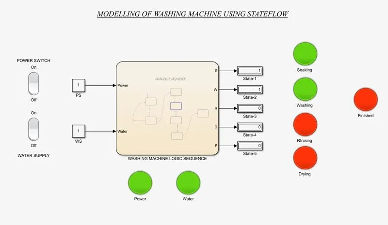
- After the soaking process for 20 seconds was completed, the washing process takes place and process for 100 seconds
- In that process the state gets activated and denoted as GREEN.
5. After Washing Process, Rinsing process activated:
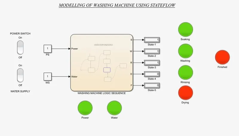
- After the washing process for 100 seconds, the rinsing process takes place and performs for 20 seconds.
- In this process it removes the residue of water.
6. After Rinsing process activated, Drying process activated:
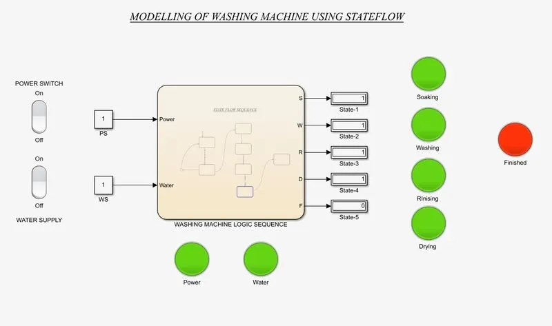
- After rinising process for 20 seconds, the drying process takes place and performs for 50 seconds.
7. After all Process Finished,
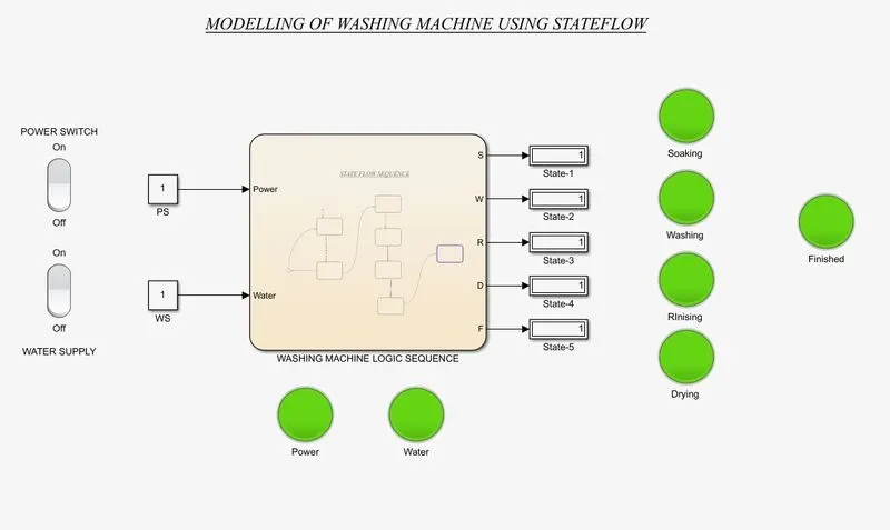
- After completion of all the process the finished lamp indicates GREEN colour, which denotes the process in soaking, washing, rinising and drying are completed wit the respective time intervels.
- After completing all the process in washing machine LED is turned ON state.
MODELLING OF GEAR SHIFT LOGIC USING STATE FLOW
AIM:
To implement the state flow of control logic for the gear shifting process.
OBJECTIVE:
- To Accelarate a speed and input is given in the simulation while running
- To display the gear number based on the speed input.
CONDITIONS:
Speed Range(km/hr) Gear
0 to 15 1
16 to 25 2
26 to 40 3
41 to 60 4
Above 61 5
INTRODUCTION:
GEAR SYSTEM:
A gear system is a device to transfer precisely the rotator motion from one point to the other. A gear is a wheel with teeth around its rim. The teeth acts as the components of a machine and they transmit rotational motion to the wheel by successively engaging the teeth of the other rotating gear.
GEAR SHIFTING MECHANISM:
Vehicle transmissions require devices to match the ratio, and thus the power available, to the prevailing driving conditions. “Power matching” is one of the main functions of a vehicle transmission
The gearshifting mechanism thus plays an important role in the interface between driver and vehicle. Its handling has a major influence on perceived comfort. The components used in a gearshifting mechanism depend largely on whether shifting gear involves interrupting the power flow. Other factors are the type of vehicle (passenger car or truck), the type of drive (front-wheel or rear-wheel drive) and the operating conditions.
COMPONENTS USED IN MODELLING:
- Circular Guage
- Slider
- Constant
- State flow chart
- States
- Transitions
- Display
- Rocker switch
- Lamp
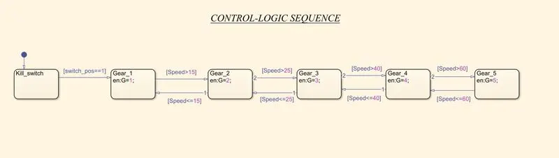
STATE-FLOW OF GEAR SHIFTING PROCESS:
INPUT AND OUTPUT PORT'S:
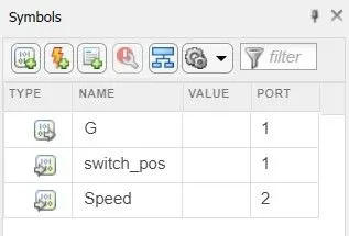
- For the state flow control logics the input and output ports are provided.
- The switch position and speed are input ports indicating kill switch position and accelarating position of tha system.
CONTROL LOGIC'S AND EXPLANATIONS IN GEAR SHIFTING PROCESS;
- The circular guage is used as a speedometer in whic the analog reading of the speed is visible based on the acclaration given by the slider.
- The slider at as a Accelarating device in the from 0 to Max speeds are varied while simulation.
- The rocker switch is used as a Ignition switc/ Kill switch and if it gets activated it indicates 1-ON state and in lamp green colour denoted.
- The the kill switch is turned OFF-0 state and the lamp indicates into RED colour the system is not getting activated.
- If the kill switch is activated and acelaration is given from the slider as input the gears are shitted as per the conditions
- First gear is activated when speed range from 0 to 15 Km/hr and the gear number are displyed.
- Second gear is activated when the speed range reaches to 16 km/hr and till 25 km/hr and respective gear number is displayed.
- Third gear is activated when the speed reaches to 26 Km/hr till 40 Km/hr and from the range the respective gears are indicated in display.
- Fourth gear is activated when the speed reaches to 41 Km/hr till 60 Km/hr the respective gear number is displayed.
- Fifth gear is activated when the speed reaches above 61Km/hr and gear number is displayed accordingly.
- Likewise, when the speed renge is reduced from 61 Km/hr to 0 Km/hr the respective gears are shifted respectively.
- The plots form the speed and gear shifting are obtained using scope block in simulink.
SIMULINK MODEL FOR GEAR SHIFTING:
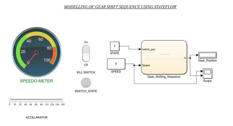
- The modelling of gear shiftting logic consists of speedometer whcih indicates analog measurement of the speed give by the slider as accelaration.
- The kill switch is provided to indicate weather ignition takes place or not and which are denoted by the GREEN or RED in colour.
KILL SWITCH IS DEACTIVATED:
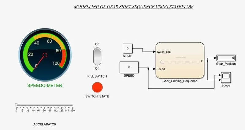
- When the kill switch is de-activated the ignition will not takes place and the gear floe process are not takes place.
- That are denoted as RED in colour.
KILL SWITCH IS ACTIVATED:
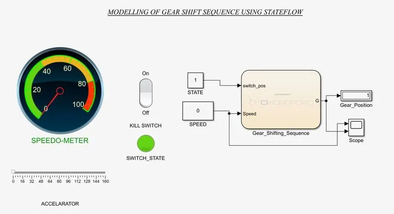
- When the kill switch is activated and indicates as GREEN in colour. The ignition in engine takes place.
- The gear system, is activated and process of control system takes place based on respective conditions.
DIFFERENT SPEED RANGES:
1. CONDITION 0-15Km/hr:
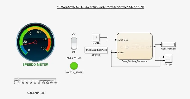
- The first gear is activated when it reach the range in between 0 to 15 Km/hr and <=15 Km/hr conditions.
- The gear position is indicated in display as 1.
2. Condition 16 - 25 Km/hr:
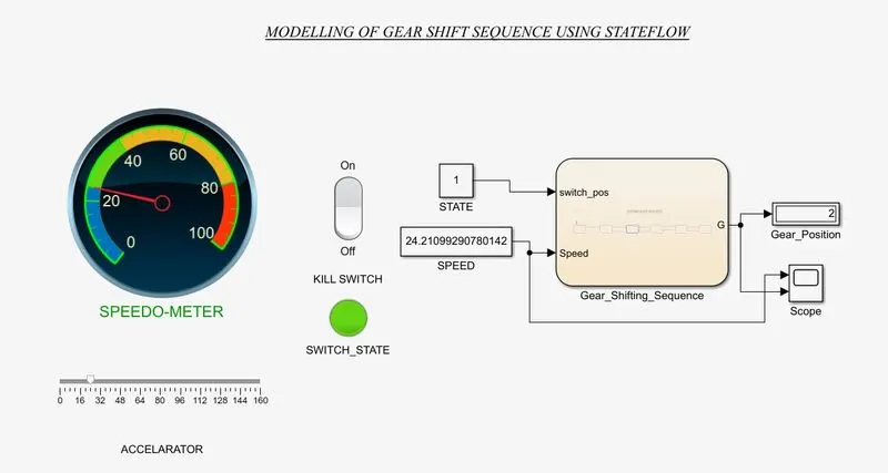
- The second gear is activated when it reach the range in between 16 to 25 Km/hr and <=25 Km/hr conditions.
- The gear position is indicated in display as 2.
3. Condition 26 - 40 Km/hr:
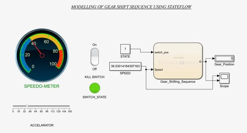
- Thethird gear is activated when it reach the range in between 26 to 40 Km/hr and <=40 Km/hr conditions.
- The gear position is indicated in display as 3.
4. Condition 41 - 60 Km/hr:
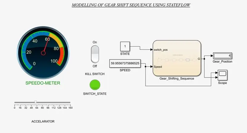
- The fourth gear is activated when it reach the range in between 41 to 60 Km/hr and <=60 Km/hr conditions.
- The gear position is indicated in display as 4.
5. Above 61 Km/hr:
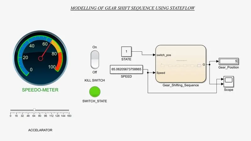
- The fifth gear is activated when it reach the range above 61 Km/hr and >60 Km/hr conditions.
- The gear position is indicated in display as 5.
PLOTTING RESULT:
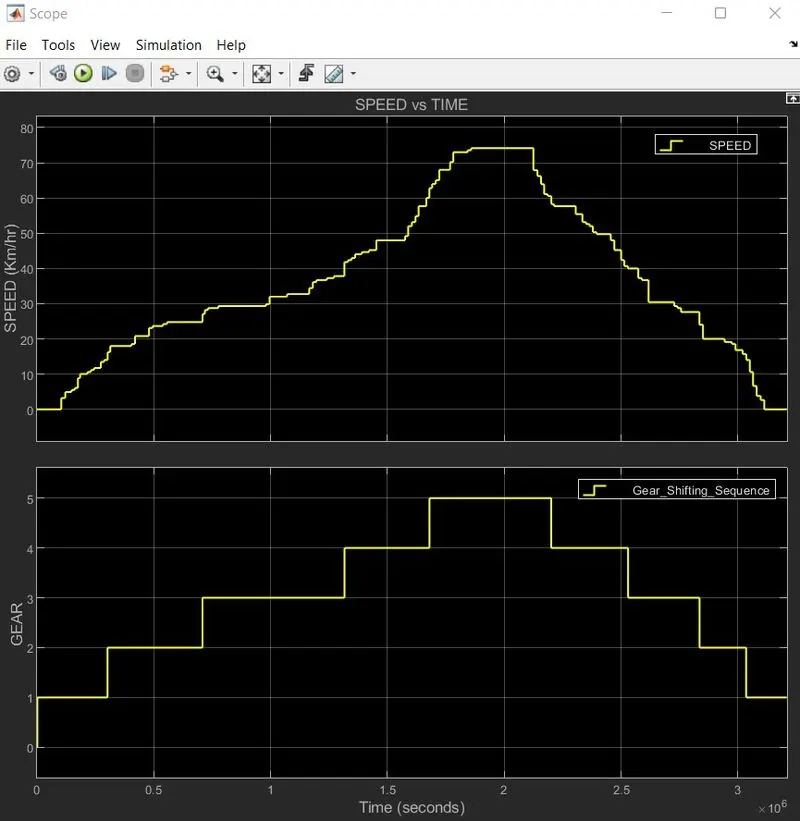
- The plot describes the variation of speeds and gear transmission sequence of state flow logics.
- Initially the speed is at o Km/hr after the accelaration given by the slider the gear is transmited based on the conditions.
- As well as, the gears are shiftted down when the speed is reduced from the condition.
CONCLUSION:
- Implemented the state machines using control logics for the sequence,
- Create a power supply for activating the system and indicated through LED, if water supply is not available.
- After completing all the process in washing machine LED is turned ON state.
- A speed is given as a input in the simulation while runningand different gear shiftings are obtained.
- Displayed the gear number based on the speed input.
- The plots for speed and Different gear shifts are plotted.