Week 14 challenge
ASSEMBLY OF BUTTERFLY VALVE
AIM:
To Assemble all the components of Butterfly Valve using Assembly Workbench and Implement GD&T to the drawing sheet.
OBJECTIVE:
- To Understand the Assembly of the Butterfly Valve Components .
- To Assemble a components of 3-D Butterfly Valve Using Assembly Workbench.
- To apply GD&T to the drawing sheet.
- To prepare a report for the Assembly of Butterfly Valve.
- To attach the Assembly file of Butterfly Valve .Part file.
INTRODUCTION:
BUTTERFLY VALVE:
A butterfly valve is a valve that isolates or regulates the flow of a fluid. A butterfly valve regulates flow by starting, slowing, or stopping media. The disk opens and closes with a low-torque rotation of 90 degrees and works for any compatible application. Because they cost less and are lighter weight, the butterfly valve is often preferred over other types of valves. The "butterfly" is a metal disc mounted on a rod. When the valve is closed, the disc is turned so that it completely blocks off the passageway. When the valve is fully open, the disc is rotated a quarter turn so that it allows an almost unrestricted passage of the fluid. The valve may also be opened incrementally to throttle flow.
APPLICATIONS OF BUTTERFLY VALVE:
A Butterfly valve can be used in many different fluid services and they perform well in slurry applications,
- Cooling water, air, gases, fire protection, etc.
- Slurry and similar services.
- Vacuum service.
- High-pressure and high-temperature water and steam services.
- Advantages of Butterfly Valves:
- Compact design requires considerably less space, compared to other valves.
- Light in weight.
- Quick operation requires less time to open or close.
- Available in very large sizes.
- Low-pressure drop and high-pressure recovery.
- Disadvantages of Butterfly Valves:
- Throttling service is limited to low differential pressure.
- Cavitation and choked flow are two potential concerns.
- Disc movement is unguided and affected by flow turbulence.
COMPONENTS OF BUTTERFLY VALVE:
- Butterfly Valve Body.
- Shaft / Stem.
- Retainer / Top Flange.
- Disc Plate.
- Lever Handle.
- Nut.
CREATION OF BUTTERFLY VALVE - COMPONENTS
(1). BUTTERFLY VALVE - BODY:
The body is the housing for the internal components and it is the main part of the butterfly valve. The body connects to two pipes on its two sides and it regulates to flow. By using the 2D drawing the butterfly valve body has to be created using the NX. The created bodied are been joined together by using Unite command.
The Butterfly Valve Body has been created using the creation of sketch. By using the sketch command the inferred plane are been selected and sketches are been created on the respective plane.
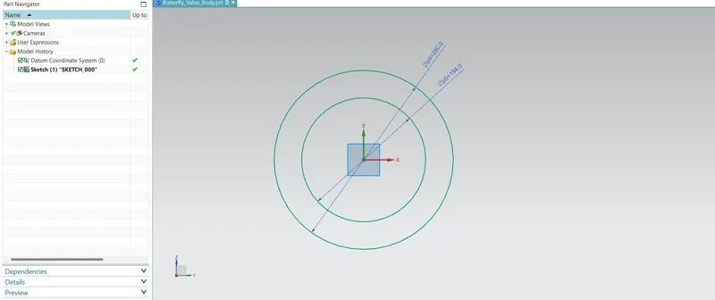
On the respective plane, the circles are been sketched with reference to the 2D drawing as 280 mm and 194 mm respectively. By using the Extrude command the curves are been selected to make the extrution and vectors are been specified and in the limits symmetry value are been selected to make the extrusion from the center plane to create symmetric body part. The side flanges are been created y creating a sketchon the respective plane and by using the Center arc command the Mis joied portions are been joined and using the trim command the boundary curve nd trim curve are been selected and trimmed it off.
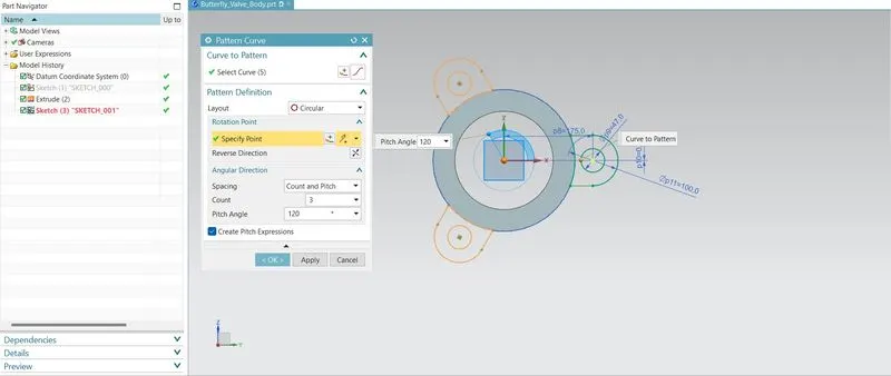
By using the pattern curve command , the curves are been selcetd and rotation points are specified as circular layout, with count and spacing as 3 and 120 deg apart. By using the extrude command and end limit as symmetry value the flanges are been created wth none boolean operation. By using the move object command, the objects are been selcted and vectors are sepecified along to the end direction of body part as copy original.
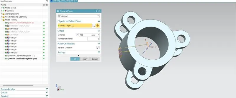
The datum plane are been created using hedefine plane on objects to the extended length as per 2 D drawing. By using the Extrude command, the curves are been selected and start limit are selected as until selected as a body part with the boolean operation as UNITE to join with the existing part body.
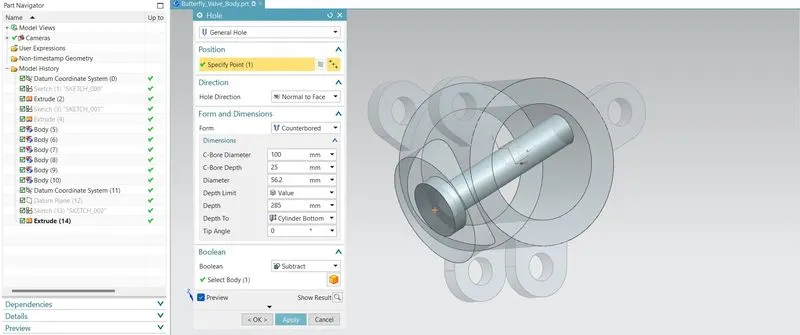
By using the Hole command, the points and directions are been specified and form are selected as counter bored. The Dimensions are specified c- Bore Diameter and depths are been specified with cylindrical bottom @ Tip angle of 0 deg. After the creation of Top cap using the Extrude command, teh holes are been created using teh craetion of sketch on the respective faces.
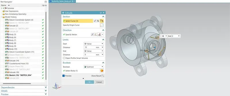
For the creation of Hole on the Base side of the Body Part, extrude commad are used to crate a Hole with the Boolean operation of SUBTRACT are been selcted and materials are removed from the body part. After the creation of all the bodies, by using the UNITE command, teh body parts are been selected and joined together.
(2). BUTTERFLY VALVE - SHAFT:
The Shaft/Stem is the internal components and it is the main part of the butterfly valve. The Shaft connects to Disc, Retainers, Butterfly Valve Body Surface contact and it regulates to flow. By using the 2D drawing the butterfly valve Stem/ Shaft has to be created using the NX. The GD&T are applied to the cretaed part on the drawing sheet.
The Butterfly Valve Shaft/Stem has been created using the creation of sketch. By using the sketch command the inferred plane are been selected and sketches are been created on the respective plane.
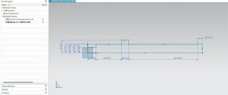
On the respective plane, the sketch has been created as per the 2-D Drawing, with the respective dimensions.
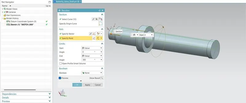
By using the Revolve command,the curve has been selected along the specified vector @ an anle of 360 degree. The shaft has been created As per the 2-D drawing. The sketch has been created on the respective plane to make the recess on the part. For that as per the respective dimensions the sketch has been created. By using the Extrude command, by specifying a vector along the symmetric directions with the boolean operation as Substract, the material has removed from the shaft part created.
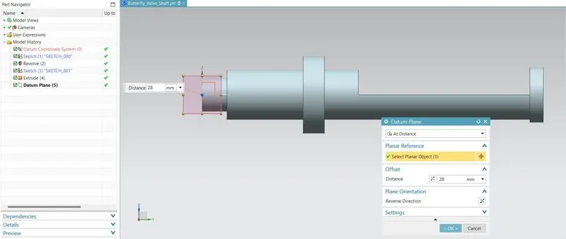
By using the datum plane command, datum are created perpendicular to the recess created. The datum's are created from a distace @ 28 mm from the selected planer object. By using the sketch, the rectangular section has been created as per the 2-D drawing.
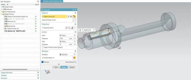
By using the Extrude command, by specifying a vector along the respective direction @ 18.5 mm with the boolean operation as Substract, the material has removed from the shaft part created. The sketch has been created on the surface of plane with respect to the postion as per the 2-D drawing. The circle are created on the respective plane to create a hole on the respective surface.
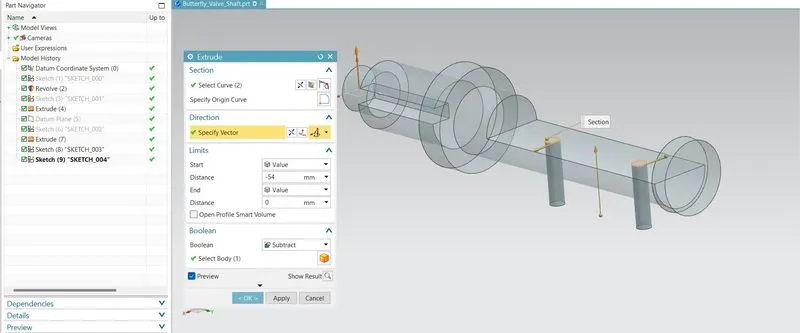
By using the Extrude command, by specifying a vector along the respective direction with the boolean operation as Substract, the material has removed from the shaft part created and holes are created. After the creation of all the features based on the 2-D Darwing, the chamfer has been performed on one end of the shaft part to access the part in an efficient manner. By using the chamfer command, the edges are selected and cross section as symetric with the distance of 3 mm. The chamfer has created.
(3). BUTTERFLY VALVE - RETAINER:
The spring Retainer ensuring the spring stays in place and supplies the correct amount of pressure on the valve spring. It control the entire valve train, ensuring that the proper amount of spring pressure is applied consistently to prevent valve bounce. By using the 2D drawing, the butterfly valve Retainer has to be created using the NX. The GD&T are applied to the created part on the drawing sheet.
The Butterfly Valve Retainer has been created using the creation of sketch. By using the sketch command the inferred plane (x-y axis) are been selected and sketches are been created on the respective plane.
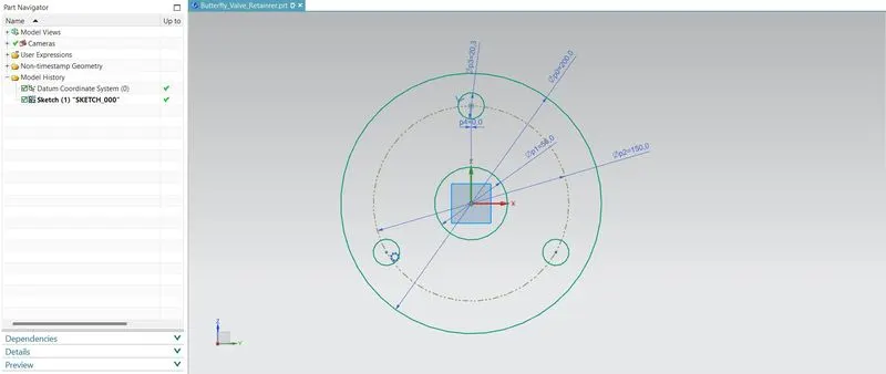
On the respective plane, using the Circle commad the sketchs are been created as per the 2-D drawing. The Diameter are provided on the selection of specified point. On the respective plane, the circular holes are been created as per the 2-D Drawing with diameter of 20.3 mm @ the distance from the center as 150 mm BCD. By using the pattern command the curve are been selected with circular layout @ the specified point with 3 counts and angle as 120 degree.
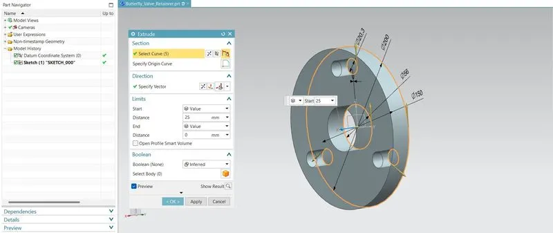
By using the Extrude command, by specifying a vector along the directions with the boolean operation as Inferred, the retainer for the Butterfly Valve has been created.
(4). BUTTERFLY VALVE - DISC PLATE:
The Disc Plate is the internal components and it is the main part of the butterfly valve. The Disc Plate Acyuate and Deacutuate the flow of fluid based on the operation performed on the Butterfly Valve. By using the 2D drawing the butterfly valve Disc Plate has to be created using the NX. The GD&T are applied to the cretaed part on the drawing sheet.
The Butterfly Valve Disc Plate has been created using the creation of sketch. By using the sketch command the inferred plane (x-y axis) are been selected and sketches are been created on the respective plane.
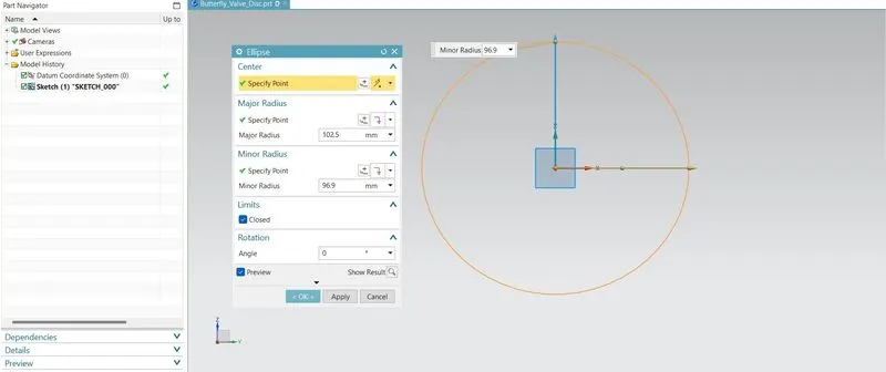
On the respective plane, using the ellipse commad the sketchs are been created as per the 2-D drawing. The Major Diameter and Minor Dimeter are provided on the selection of specified point with ange of revolution as 0 degree.
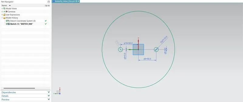
On the respective plane, the two holes are been created as per the 2-D Drawing with diameter of 12.5 mm @ the distance from the center as 50 mm apart.
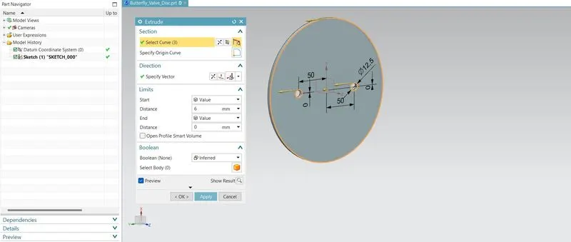
By using the Extrude command, by specifying a vector along the directions with the boolean operation as Inferred, the Disc plate for the Butterfly Valve has been created.
(5). BUTTERFLY VALVE - LEVER HANDLE:
The Lever Handle in the Butterfly valve act as a External component by which it act as a controller, relative to the Shaft and the Nut of the butterfly Valve. It is fixed at the top end of shaft to keep the Pressure on the Nut. Levers are available for on/off and throttling control of butterfly valves. By using the 2D drawing the butterfly valve Lever Handle has to be created using the NX. The GD&T are applied to the cretaed part on the drawing sheet.
The Butterfly Valve Lever Handle has been created using the creation of sketch. By using the sketch command the inferred plane (x-y axis) are been selected and sketches are been created on the respective plane.
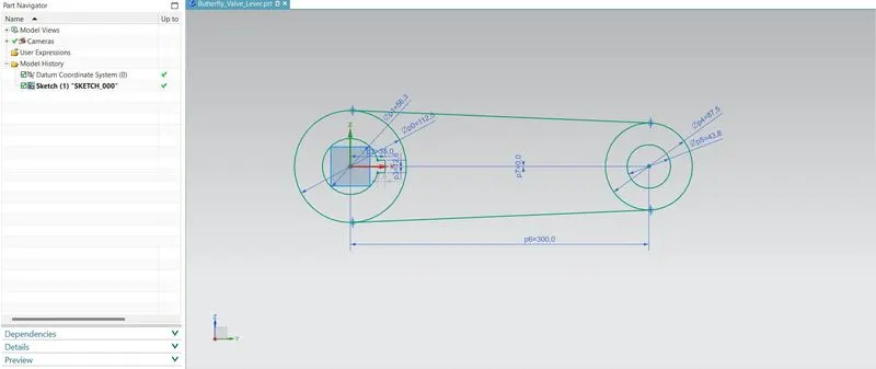
On the respective plane, using the Circle commad the sketchs are been created as per the 2-D drawing. By using the line command the center Area are been created.
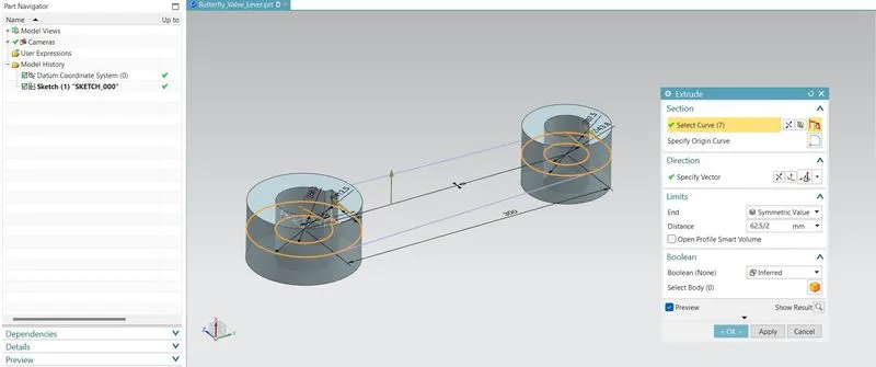
By using the Extrude command, by specifying a vector along the directions with the boolean operation as Inferred and the limits are ended with Symmetric, the Lever Handle for the Butterfly Valve has been created @ 31.25 mm extruded.
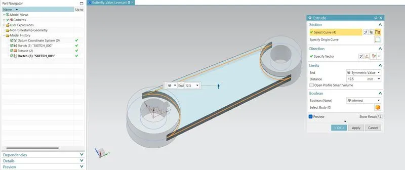
By using the Extrude command, by specifying a vector along the directions with the boolean operation as Inferred and the limits are ended with Symmetric, the Lever Handle for the Butterfly Valve has been created @ 12.5 mm extruded.
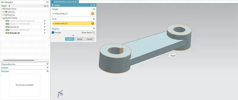
After the creation of all the bodies, by using the UNITE command, the body parts are been selected and joined together.
(6). BUTTERFLY VALVE - NUT:
The Nut in the Butterfly valve act as a External component by which it act fastner, relative to the Shaft and the Lever of the butterfly Valve. It is fixed at the top end of shaft to keep the lever and retainer on position relative to the body of butterfly valve. By using the 2D drawing the butterfly valve Nut has to be created using the NX. The GD&T are applied to the cretaed part on the drawing sheet.
The Butterfly Valve Nut has been created using the creation of sketch. By using the sketch command the inferred plane (x-y axis) are been selected and sketches are been created on the respective plane.
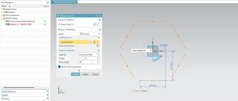
On the respective plane, using the line commad the sketchs are been created as per the 2-D drawing. By using the pattern command the curve has been selected with the circular layout and revolution point are been specified @ center. On the respective plane, the lines has been extended to the smaller extent. Then by using the tirm command the excess portions are been trimmed off. The Shaft Hole are Sketched as per the 2-D drawing.
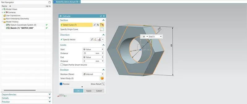
By using the Extrude command, by specifying a vector along the directions with the boolean operation as Inferred, the Nut for the Butterfly Valve has been created @ 25mm extruded.
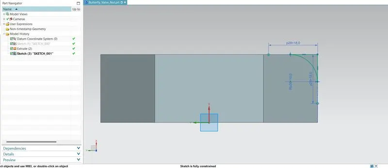
By using the sketch command the plane are defined on the respective plane ans using the line command perpendicular lines are been created and using the fillet command the Radius of 10 mm are filleted and Excess portions are been trimmed off.
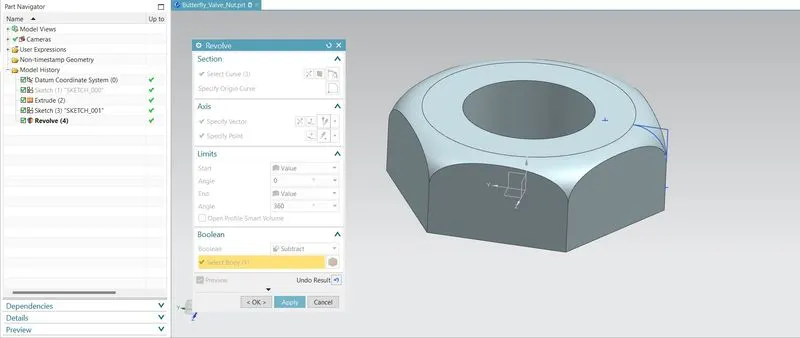
By using the Revolve command, the Arc curves are selected and Axis throgh the rotation also selected @ an angle of 360 degeree by which the fillets are created at the end point and Nut for the Butterfly Valve are created.
ASSEMBLY OF BUTTERFLY VALVE COMPONENTS
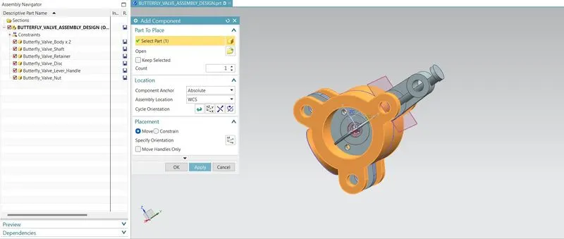
By using the Add Component command in Assembly Workbench, the parts of Butterfly Valve are been Imported into te Assembly workbench by which the Assembly of components are done.
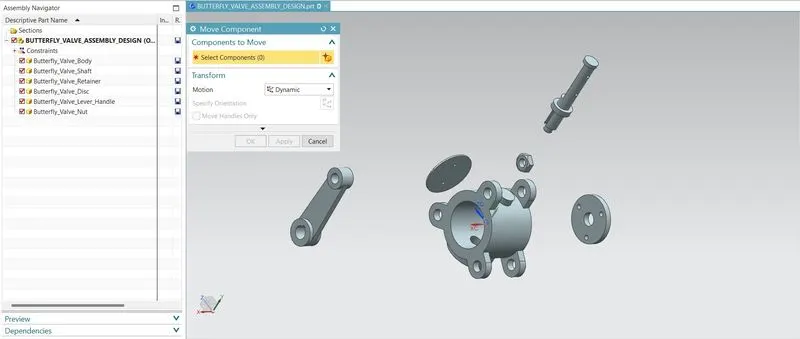
By using the Move Components command in Assembly Workbench, the components are been Moved along the differnet orientations through whic Assembly is done.
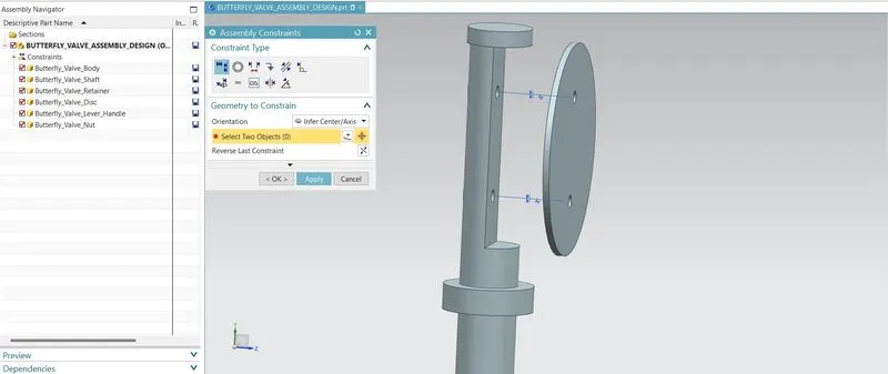
The Shaft and the Disc Plate are been constrained usin the Infer center axis command, by using the Touch Constraint the Shaft and Disc Plate are been Assembled together.
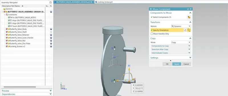
By using the Locking Screws, the Shaft and Disc Plate are fastened Together, In the Move command, Using copy Mode the Locking screws are been copied and used to Assemble Together.
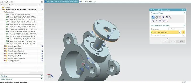
The Retainer of Butterfly Valve are been Assembled Together with the Body of Buterfly Valve using the Touch and Infer center Axis commands.
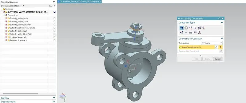
The Nut of the Butterfly lave are been Assembled Together relative to the shaft and Lever Handle of the Butterfly Valve and Assembled Together.
ASSEMBLY OF BUTTERFLY VALVE:
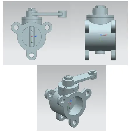
IMPLEMENTING GEOMETRIC DIMENSIONING & TOLERECING
GEOMETRIC DIMENSIONING AND TOLERENCING:
Geometric Dimensioning and Tolerancing (GD&T) is a system for defining and communicating engineering tolerances and relationships. It uses a Symbolic Language on Engineering Drawings and computer-generated three-dimensional Solid Models that explicitly describe nominal geometry and its allowable variation.
GD&T is used to define the nominal (theoretically perfect) geometry of parts and assemblies, to define the allowable variation in form and possible size of individual features, and to define the allowable variation between features.
SIGNIFICANCE OF GD & T:
- Dimensioning specifications define the nominal, as-modeled or as-intended geometry.
- Tolerancing specifications define the allowable variation for the form and possibly the size of individual features, and the allowable variation in orientation and location between features.
APPLY GD&T ON THE COMPONETS OF BUTTERFLY VALVE:
The Plus-Minus tolerencing, profile of surface, Position tolerene and flatness are been applied on the drawing sheet for the creation of Shaft / Stem of Butterfly Valve.
- The Primary Datum are selected as the surfaces that mate with the body of the butterfly valve part. The Datums are named as "A1" and "A2" , which are combind and called as Datum "A", by which the dgeress of freedom (Translational & Rotational DOF) are arrested.
- The secondary datum are been selected as the base surface that mate with the bottom of the Body of Butterfly valve with the flatneess of 0.25 mm. The Flatness tolerenes are not associated with Datum. By which the Translatonal DoF are been arrested.
After the creation of 3 -D Retainer, the drawing sheet has been created to make the GD&T on the drawing sheet by which the positioning and assembly of the Retainer to the Butterfly Valve has been done in a proper manner.
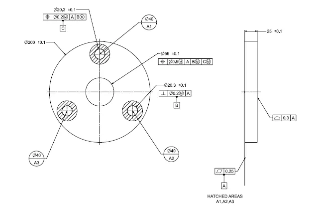
- The Primary Datum are selected as the surfaces that mate with the body of the butterfly valve part. The Datums are named as "A1" ,"A2" and "A3", which are combind and called as Datum "A", by which the dgeress of freedom (Translational & Rotational DOF) are arrested.
- The secondary datum are been selected as the feature of hole that mate with the surface of the Body of Butterfly valve with the perpedicular tolerence of 0.2 mm associated with Maximum Material Condition.
- The Tertairy datum are been selected as the feature of hole far from the datum "B" that mate with the surface of the Body of Butterfly valve with the position tolerence of 0.2 mm associated with Maximum Material Condition with respect to datum A and B.
After the creation of Disc Plate 3 -D Disc Plate, the drawing sheet has been created to make the GD&T on the drawing sheet by which the positioning and assembly of the Disc Plate to the Butterfly Valve has been done in a proper manner.
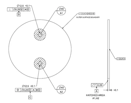
- The Primary Datum are selected as the surfaces that mate with the body of the butterfly valve part. The Datums are named as "A1" and "A2" , which are combind and called as Datum "A", by which the dgeress of freedom (Translational & Rotational DOF) are arrested.
- The secondary datum are been selected as the feature of hole that mate with the surface of the Body of Butterfly valve with the perpendicular tolerence of 0.25 mm associated with Maximum Material Condition with reference to datum "A".
- The Tertairy datum are been selected as the feature of hole far from the datum "B" that mate with the surface of the Body of Butterfly valve with the position tolerence of 0.25 mm associated with Maximum Material Condition with respect to datum A and B.
After the creation of 3 -D Lever Handle, the drawing sheet has been created to make the GD&T on the drawing sheet by which the positioning and assembly of the Disc Plate to the Butterfly Valve has been done in a proper manner.
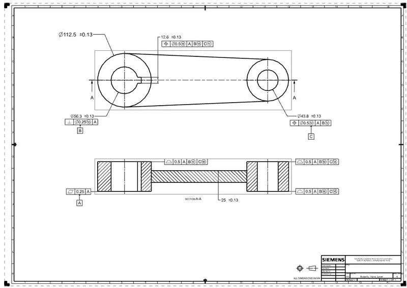
- The Primary Datum are selected as the surfaces that mate with the body of the butterfly valve part. The Datums are called as Datum "A", by which the dgeress of freedom (Translational & Rotational DOF) are arrested.
- The secondary datum are been selected as the feature of hole that mate with the internal surface of the Body of Butterfly valve with the perpendicular tolerence of 0.25 mm associated with Maximum Material Condition with reference to datum "A".
- The Tertairy datum are been selected as the feature of hole far from the datum "B" that mate with the surface of the Body of Butterfly valve with the position tolerence of 0.5 mm associated with Maximum Material Condition with respect to datum A and B.
After the creation of Disc Plate 3 -D Disc Plate, the drawing sheet has been created to make the GD&T on the drawing sheet by which the positioning and assembly of the Disc Plate to the Butterfly Valve has been done in a proper manner.
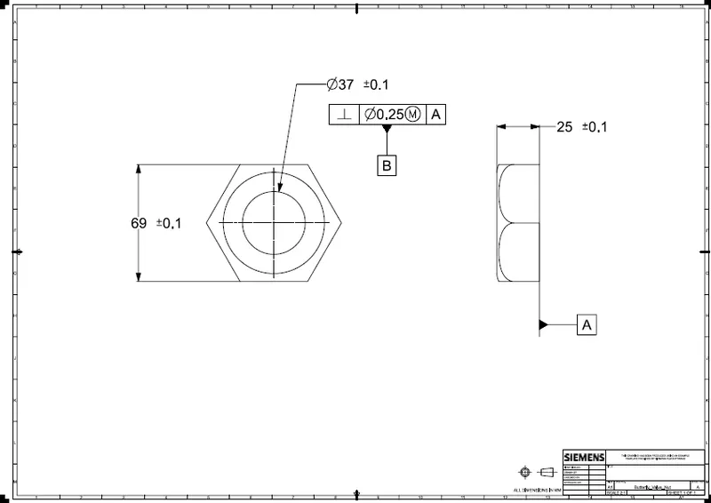
- The Primary Datum are selected as the surfaces that mate with the body of the butterfly valve part. The Datums are called as Datum "A", by which the dgeress of freedom (Translational & Rotational DOF) are arrested.
- The secondary datum are been selected as the feature of hole that mate with the internal surface of the Body of Butterfly valve with the perpendicular tolerence of 0.25 mm associated with Maximum Material Condition with reference to datum "A".
IMPLEMENTING GEOMETRIC DIMENSIONING & TOLERECING FOR ASSMBLY OF BUTERFLY VALVE
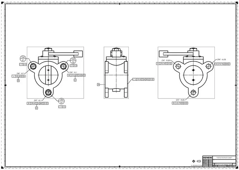
Based on the Assembly and Functioning of te Butterfly Vlave, Primary, secondary and Teritairy of the Butterfly Valve are been Implemented. The Plus-Minus tolerencing, Position tolerene and flatness are been applied on the drawing sheet for the Assembly of Butterfly Valve.
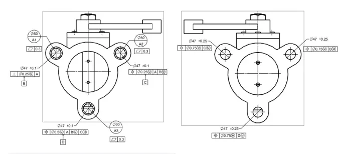
- The Primary datum are been craeted by understanding the assembly of butterfly valve.
- The Primary Datum are selected as the surfaces that mate with the Functioning of the butterfly valve part. The Datums are named as "A1" ,"A2" and "A3", which are combind and called as Datum "A", by which the dgeress of freedom (Translational & Rotational DOF) are arrested.
- The Datum Targets are been Implemented with flatness of 0.3.
- The secondary datum are been selected as the feature of hole that mate with the surface of the Functioning of Butterfly valve with the perpedicular tolerence of 0.2 mm associated with Maximum Material Condition with respect to Datum "A".
- The Tertairy datum are been selected as the feature of hole far from the datum "B" that mate with the surface of the Functioning of Butterfly valve with the position tolerence of 0.25 mm associated with Maximum Material Condition with respect to datum A and B.
- The profile of surface are is applied with the tight tolerene of 0.5 mm with respect to the datum "A,B and C".
- The datum are been selected as the feature of hole that mate with the surface of the Functioning of Butterfly valve with the position tolerence of 0.75 mm associated with Maximum Material Condition with respect to Datum "D, B and C".
CONCLUSION:
- The 2-D Darwing of the Butterfly Valve Lever Components are Understood and 3-D Component are created.
- The components of 3-D Butterfly Valve are created.
- The GD&T to the drawing sheet symbols are been applied based on the assembly and Functioning of the Butterfly valve.
- The report for the creation of Assembly of Butterfly Valve Design are explained.
- The created Assembly file of Butterfly Valve .Part file are attached.