Design of backdoor
BACKDOOR ASSEMBLY DESIGN
AIM:
To Create a Backdoor Assembly design by developing the essential Reinforcements and Embosses and also to perform Draft Analysis.
OBJECTIVE:
- To Create an Assembly for the Backdoor by developing essential Reinforcements and Embosses.
- To Analyse the draft on the Reinforcements and Outer upper and Outer Lower Panels
- To develop the Reinforcements (Hinge Reinforcement, Gas Stay Reinforcement, Latch/Stricker Reinforcements, Wiper Motor Reinforcements ) as seperate Parts.
- To Design the backdoor assembly by using the appropriate Design Methodologies.
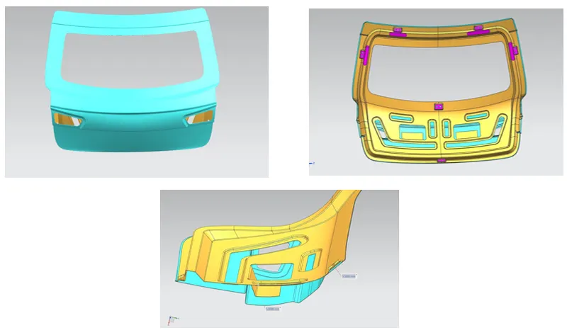
- To create an Assembly of Backdoor Inner Panel, Outer Panel, Latch, Hinge and the Reinforcements.
- To create a detailed report about the Bckdoor Design by explanationing about Backdoors and its components, Latch Trajectory, Mastic Data, Emboss Definitions.
- To Explain about the Various Manufacturing process involved in Creation of Backdoor.
INTRODUCTION:
BODY IN WHITE (BIW):
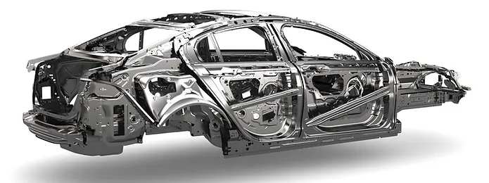
In the Automotive Industry BIW (Body in White) is the common terminology used to mention the car sheet metal welded structure (body shell). Sub-assemblies like Under body, Body side Left Hand Side/ Right Hand Side, Front End, Roof etc. gets welded together by various metal joining process like resistance spot welding, Laser welding, MIG welding to make welded metal shell (Without Door, Trunk-lid / Tailgate, Fender, Hood) called Body in White. Automotive car shell made before painting is called Body in White.
BACKDOOR:
The back door, is also referred to as the "Hatch," "Tailgate," "Trunk-lid," or "Boot-door. It's the region behind the last passenger seats generally. It has striker mounting as well as wiper motor mounts, tail lamps, and hinges to support the weight of the trunk when it is open, gas stays to help open and close the trunk, radars, cameras, and other features. . It helps in covering the luggage area with the help of sealant which keeps inside of the vehicle air tight and prevents water to enter into the car.
A Door is a hinged part which is used for entry and exit of the vehicles. Backdoor are one of the type of door of the vehicle which are located next to the passenger seat which provides access to the luggage compartment. In the most of the cars, these back door are operated with the help of gas stay which in turn reduces the effort required to lift the door. Some luxury cars have powered lifter backdoor which in turn is driven by an electric motor. This kind of system is also called a powered trunk lid system hatchback or station wagons.
TYPES OF BACKDOORS MOUNTED:
Based on the opening and closing of the backdoor that are hinged @ the top, side and bottom, the backdoors are been classified into various types,
(1). Top Mounted
(2). Side Mounted
(3). Bottom Mounted
(1). TOP MOUNTED BACKDOOR:
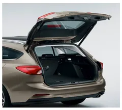
A modern cars use top mounted tailgating system which are both powered and also gas stay supported. These top mounted tailgates provide greater rear visibility compared to side mounted or backdoor which have center pillars in it. This type of back doors is used in a station wagon, pickup trunk and some of the spot utility vehicles.
(2). SIDE MOUNTED BACKDOOR:
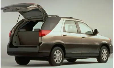
The side mounted doors are a lot easier compare to top mounted doors. These doors are generally smaller in size and can be easily accessed. These doors are more convenient for the goods handlers for long pipe and lengthy components where one door is kept open. These door also save accidental head impacts. It is a lot easier to load and unload items in the side mounted doors
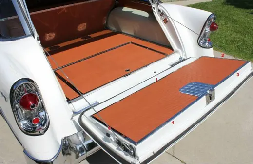
(3). BOTTOM MOUNTED BACKDOOR:
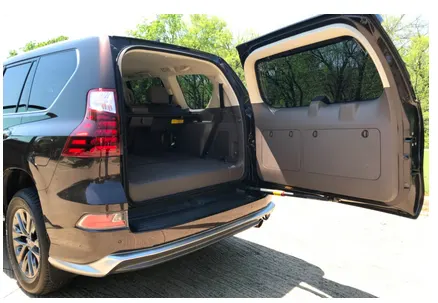
This bottom type backdoor system are used in the car type such as car, pickup truck and some luxury SUVs. These are the most convenient type of back door in which the bottom split is used as a support.
TYPES OF OPENING MECHANISMS:
Based on the Opening Mechanism in Backdoor, there are majorly two types inoder to open the Backdoor effectively,
(1). Gas Stay Mechanism
(2). Power Lifter Mechanism
(1). GAS STAY MECHANISM:
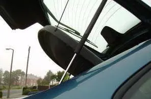
Gas Stay Mechanism in backdoor is used from lower segment car to luxury car segment. This type of car back door is very less weight. It is operated without heavy efforts. The ideal components of Bckdoor consist of a hinge, door, gas stay and some rubber beadings for sealing of door.
(2). POWER LIFT MECHANISM:
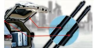
Power Lift system consists of a power latch, Anti pinch switch, Main switch. The anti pinch switch is located in order to avoid accidental hand insertion during the operation of the door. When the switch is pressed in the compartment or outside the power latch releases the latch and the entire backdoor is opened. Power lift system is opening mechanism which is to automatically open and close of the trunk and release of the latch by the touch of a bottom.
MATERIALS FOR BACKDOOR:
The Most commonly used material for back door is Steel, but it is heavy weight. So, it reduces the fuel efficiency and open and closing operations are quite difficult. So, instead of steel, aluminium are used in back door which is less dense material and suitable for complex shapes. We can give thickness locally by coating. If we are using aluminium, we can reduce the number of parts and cost.
DIFFERENT MANUFACURING PROCESSES:
The most important design consideration of any component is manufacturing aspect. In sheet metal, the component is manufactured by press tool dies. The Press tool is stamping which includes cutting operations like shearing, piercing etc. and forming operations like bending, Deep drawing, hemming etc.
FORMING PROCESS:
Forming describes the process of transforming the flat metal into another shape by applying force. It is accomplished in one of several ways, depending on the design specifications for the part. With a series of operations, the metal can be altered from a relatively simple shape into a complex one.
DEEP DRAWING:
The deep drawing is used to manufacture a product with seamless, complex shapes. This is tool related manufacturing process where the metal is stretched or extended between two tool halves to create prospective shape.
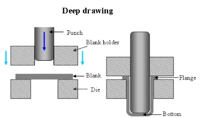
The process involves a punch with a round comer and a die with a large radius. The punch-die clearance is slightly larger than the thickness of the sheet metal to be deep drawn. As the load applied through the punch, the sheet metal is forced to flow radially and sink into the die cavity to form a cup. The process is best suitable for complex shaped problems. Deep drawing is one of the most widely used processes in sheet metal forming. Apart from its use in many other sectors, it is applied in the automotive industry for the manufacturing of car body parts.
BLANKING AND PIERCING:
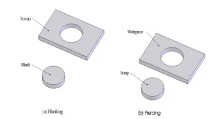
Blanking and piercing are the shearing processes in which a punch and die are used to produce parts from coil or sheet stock. The blanking produces the outside features of the component, while piercing produces internal holes or shapes.
EMBOSSING:
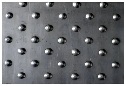
Sheet metal embossing is a stamping process for producing raised or sunken designs or relief in sheet metal. This process can be made by means of matched male and female roller dies, or by passing sheet or a strip of metal between rolls of the desired pattern.
HEMMING PROCESS:
Hemming is the technology used in the automotive industry to join inner and outer closure panels together. It is the process of bending/folding the flange of the outer panel over the inner one. The accuracy of the operation affects significantly the appearance of the car's outer surfaces, and is therefore a critical factor in the final quality of a finished vehicle. Hemming is performed in order to achieve a better final geometry in the vehicle's part and add resistance and rigidity to the part. Also, to allow a safe handling of the part.
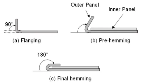
The panels which are visible outside are joined with the inner panels or supports with the help of the hemming process. Hemming is comes into for outer panels because thermal joining processes leave the residual marks which are acceptable on the aesthetic surfaces.
ROLL HEMMING:
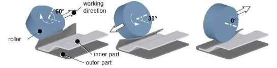
Roll hemming is carried out incrementally with a hemming roller. Roll hemming is very flexible to use and tool costs are significantly lower as compared to those of conventional die hemming. However, the cycle times are much higher since the hemming is realized using a hemming roller which follows a defined path. Roll hemming operation can also be divided into several pre-hemming and final hemming process steps.
APPLICATIONS OF SHEET METAL STAMPING PROCESS:
- In the stamping process, sheet metal is transformed into complex parts using highly specialized computer-aided drafting and manufacturing programs.
- Sheet metal stamping produces superior, resilient, heavy-duty parts quickly and efficiently.
- The results are so precise, they’re typically more reliable and consistent than manual machining.
BACKDOOR THICKNESS:
- Outer Panel Thickness `= 0.75mm`
- Inner Panel Thickness `= 0.75mm`
- Reinforcement Thickness `= 1.5mm`
DESIGN CONSIDERATIONS FOR BACKDOOR:
- Rear Visibility Criteria
- Crash requirements
- Amount of space needed (Boot Space)
- Accessibility
- Backdoor opening Mechanism
- Mountings
- Latch and striker placement
- Wiper motor placement
- Hinge and gas stay placement
- Reinforcements
- Sealing criteria
- Crash requirements
- Clearances
- Reliefs
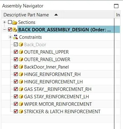
COMPONENTS IN HOOD ASSEMBLY DESIGN:
- BackDoor Outer Panel - Upper
- BackDoor Outer Panel - Lower
- BackDoor Inner Panel
- Hinge Reinforcement RH
- Hinge Reinforcement LH
- Gas Stay Reinforcement RH
- Gas Stay Reinforcement LH
- Wiper Motor Reinforcement
- Stricker & Latch Reinforcements
DESIGN METHODOLOGY FOR BACKDOOR DESIGN:
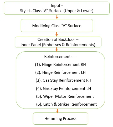
INPUT STYLISH BACKDOOR A SURFACE:
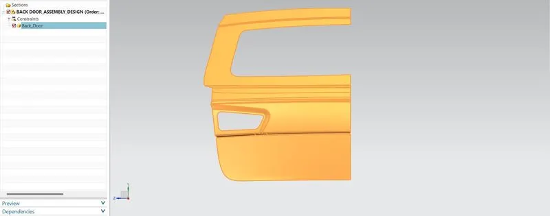
The Input Stylish class "A" Surface are given by which the surface design are been check and inspected uising the sew command. The irregularity of the surfaces are been Recreated by Hiding the Improper Calss "A" Fillet areas and Recreated using respective commands.
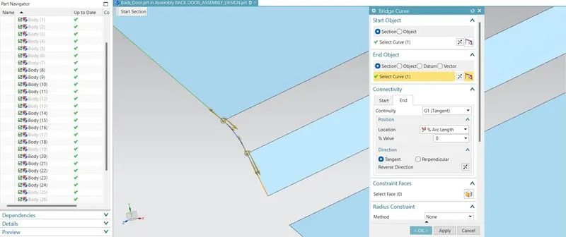
By using the Bridge curve command the start and the end objects are selected and curves are given with the G1 continuity.
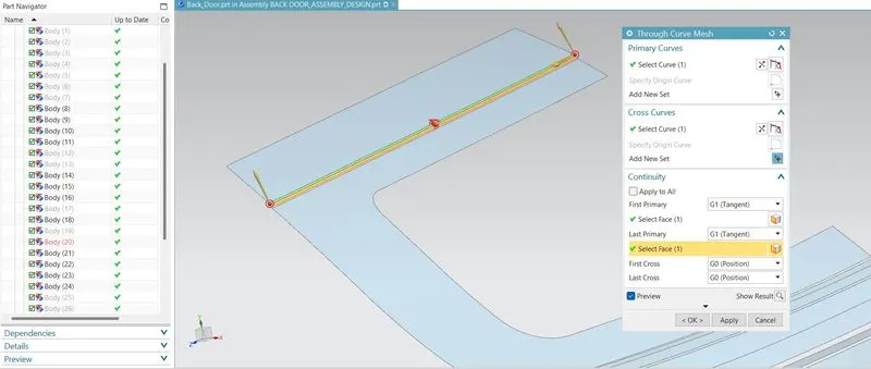
By using the Through curve mesh command the primary curve and the cross curves are selected respectively and tangent faces are selected accordingly, the surfaces are been created.
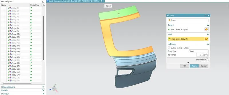
By using the sew command the target surfaces and tool surfcaes are been selected and sewed together.
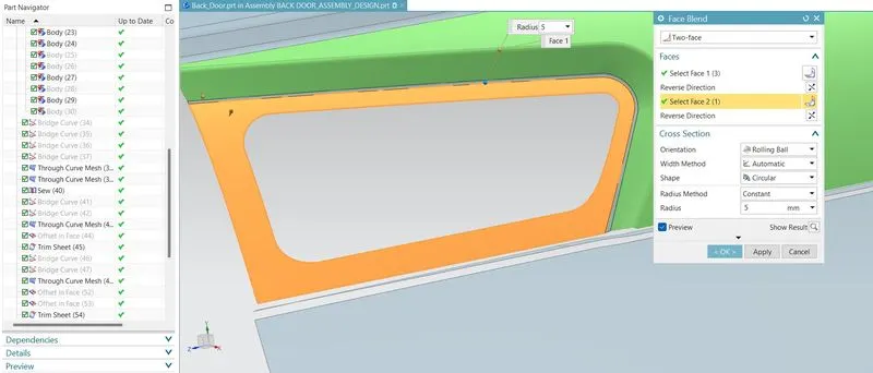
By using the face blend command the faces are been selected to craete a blend between the surfaces with radius of 5 mm.
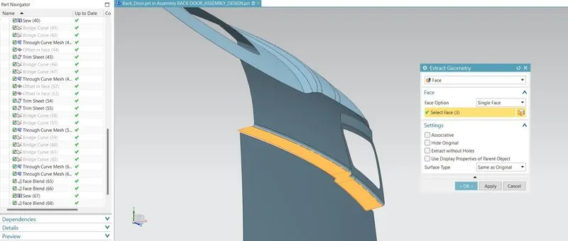
By using the extract Geometry command, the faces are been selected and using the extend sheet command the edges are selected and extended respectively.
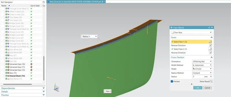
By using the Face Blend commad the faces are been selected and filleted repectively.
CREATION OF BACKDOOR OUTER PANEL - UPPER:
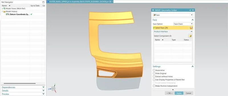
By using the Wave Geometry Linker, the faces are been selected and linked face are created. By using the linked face the working surfaces are been created for the creation of inner panel.
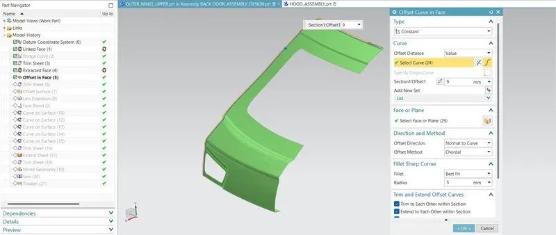
By using the Offset curve in face command the edges are selected tangently and trimmed it off using the Trim sheet command and using the Law extension the symmetric facses are been created.
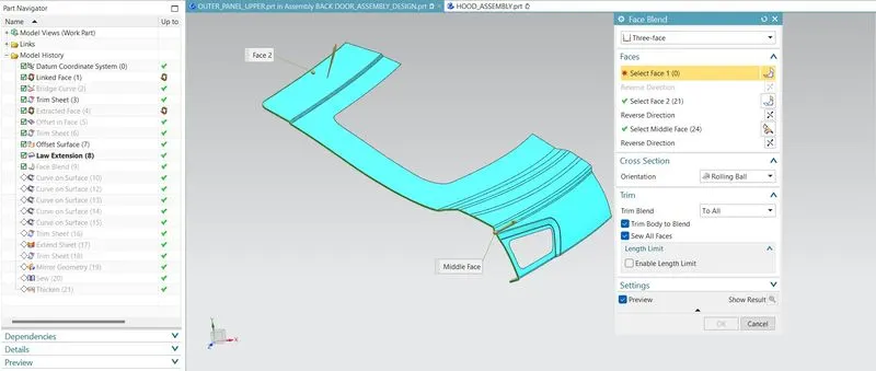
By using the face blend command the face 1, face 2 and middle faces are bee selected and blends are applied on the edges of the Outer Upper panel.
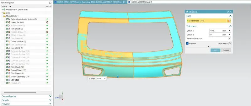
By using the thicken command the Backdoor Outer Upper panel are been Thickned to 0.75 mm.
CREATION OF BACKDOOR OUTER PANEL - LOWER:
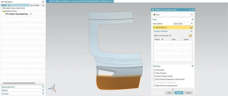
By using the Wave Geometry Linker, the faces are been selected and linked face are created. By using the linked face the working surfaces are been created for the creation of ineer panel.
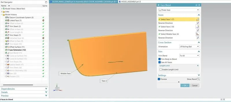
By using the face blend command the face 1, face 2 and middle faces are bee selected and blends are applied on the edges of the Outer Lower panel.
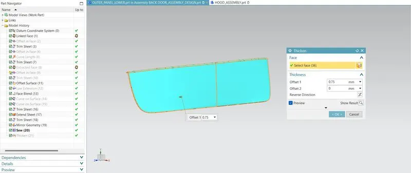
By using the thicken command the Backdoor Outer Lower panel are been Thickned to 0.75 mm.
CREATION OF BACKDOOR INNER PANEL:
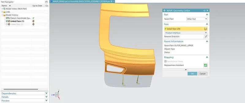
By using the wave Geometry, the body faces are been selected and linked faces are been created as a single surfaces.
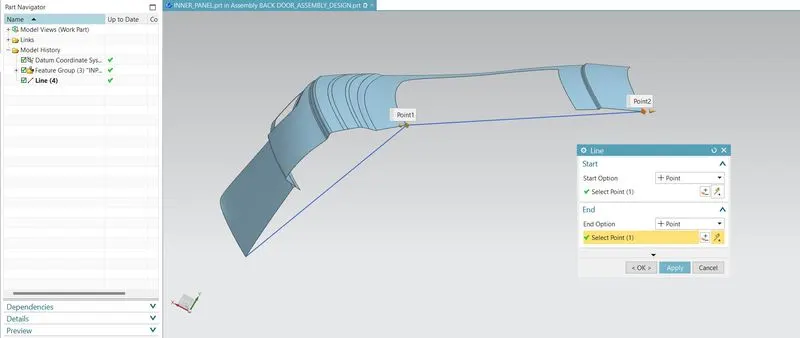
The Tooling Axis are been created by creating a sketch, the line command are selected and with the end points athe line are sketched.
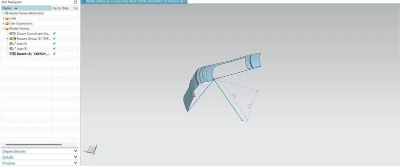
The Derived line command are used to create a line perpendicular to the two lines selected as a tooling direction.
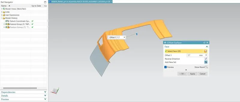
The working surfaces are created by offseting the Outer panel uper and lower at the distance of 1.7 mm downward for the creation of Backdoor Inner Panel.
CREATION OF SEALING FLANGES:
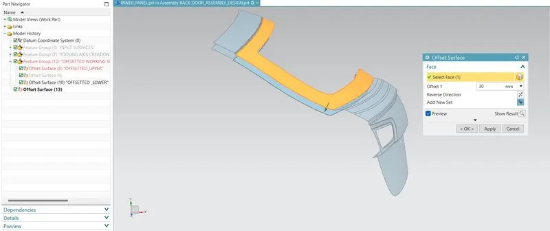
By using the offset surface command the working inner pannel surface are been offsetted @ the distance of 30 mm by selecting the respective faces.
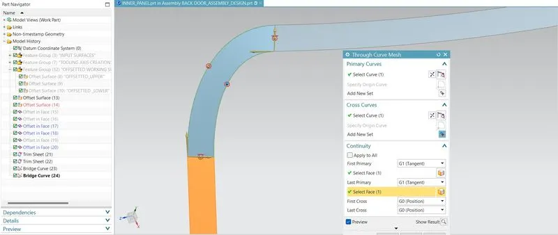
The offset curve on surface command is used to create a offsetted curve for the respective distance and using the trim sheet command the selected surfaces are trimmed it off and using through curve mesh command the guide curves and cross curves are been selected and surfaces are been created.
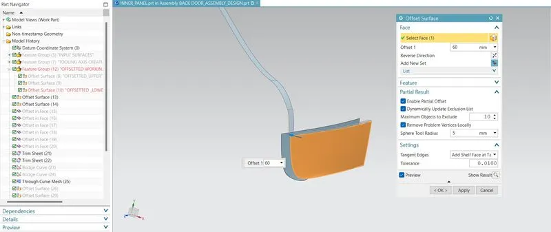
By using the offset surface command the working surface - Lower panel are been offsetted to the distance of 60 mm to create a smooth sealing flange by the surface.
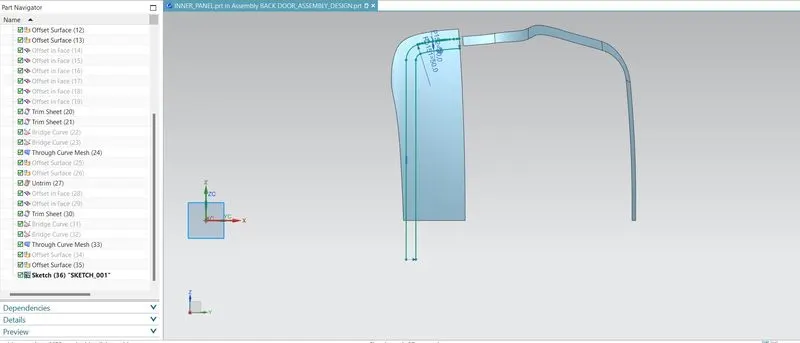
By using the sketch comand the respective plane are been selected and sketches are been drawn to create a Lower panel sealing flange.
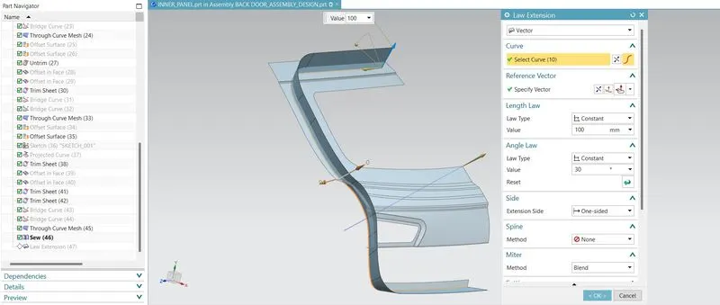
The Law extension command is used to create a flange, along the vector as a tooling direction at an angle of 30 degree.
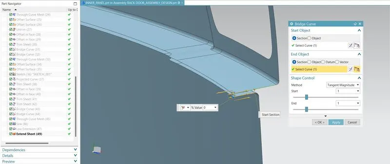
By using the bridge curve command the Upper and the Lower panel are joined together by building a bridge curve between the upper and lower surfaces.
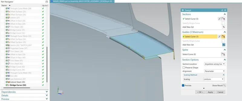
By using the swept command the curve and the guide edges are been selected to create a blended joints to the surfaces on upper and lower.
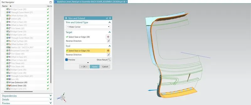
By using the trim and extend command the target and tool faces are been selectd and creating a corner with that command.
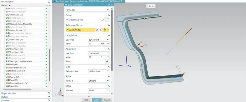
By using the law extension, by selecting the edges and vector as a tooling direction at an angle of 15 degree are created. BY using the trim and extend command the flages are created. The windshield region are created by using the Extracted working surfaces and created.
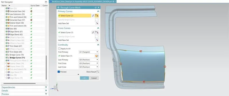
The Through curve mesh command are used to create a surface below the Wind shield region. By uisng th through curve mesh, the primary curve and the cross curve are been selected by which thesurfaces are been created.
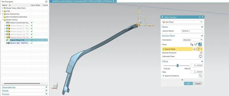
By using the clip section or View section command, the faces are been cutted ff to craete a respective embosses on the Inner panels.
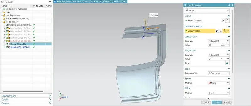
By using the law extension command the created sketch are been extended to the vector as plane and the distance symmtry as 15 mm.
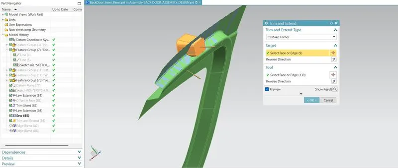
By using the law extension the embossed faces are been created and using sew command the faces are selected and sewed together. Trim and extend command are used to create a Hinge Location Emboss on the inner panel.
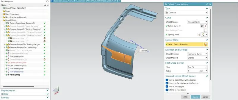
By using the offset surafe command, the faces are offsetted from the working surfaces and trimmed it off using trim sheet command.
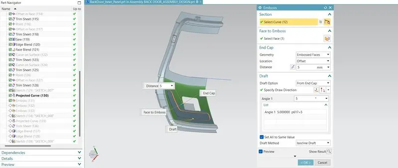
By selecting the respective plane to create a sketch on the respective plane by which the embossing sketches are been created and using the emboss command the end faces are selected and creating the emoboss at a distance of 5 mm from the surface.
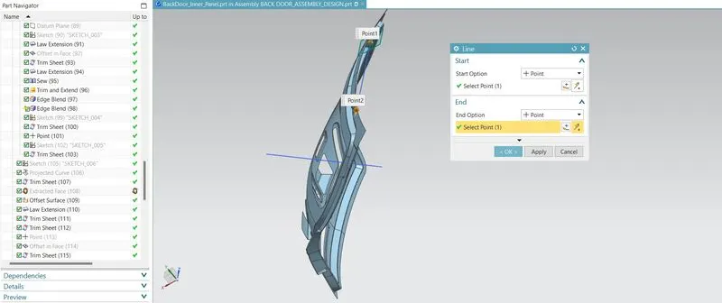
The hinge axis are created by selecting a lineby defining the two points on the hinge mounting area by creatingthat the Hinge Axis are been craeted.
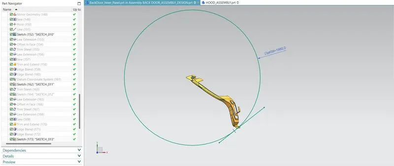
The trajectory circle are created using the circle command @ diameter of 1980 mm. The line are craeted tangent to the circle and the Latch and stricker embosses are been created.
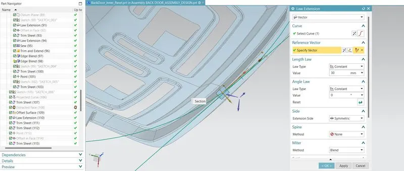
The Latch and the Striker Emboss are been created by using the law extension along the plane vector and the emobosses are been created.
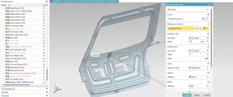
The wiper motor embosses are been created by using the Law extension and sewed a surfaces by using the sew command . The trim and extend command are used to create the wiper motor Mounting on the Inner panel.
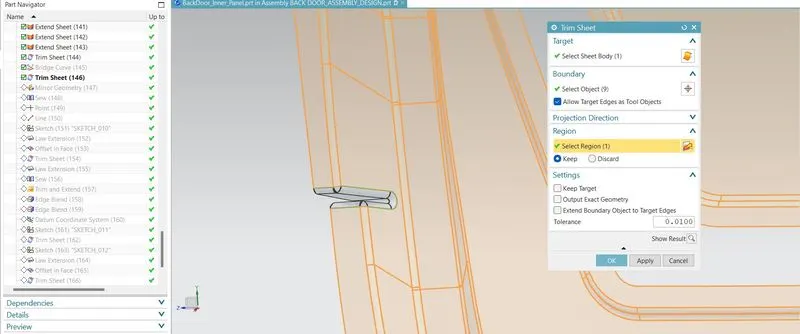
By using the trim sheet commandn the region to trim are been selected and trimmed it off.
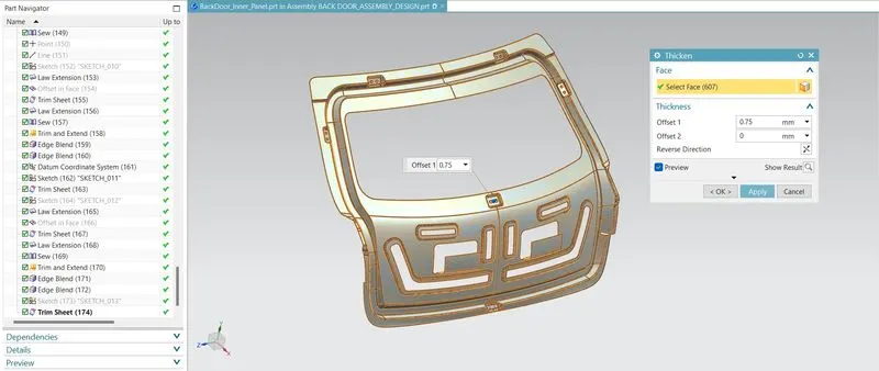
By using the Thicken command the Entire faces are been selected to Thicken at 0.75 mm.
CREATION OF REINFORCEMENT :
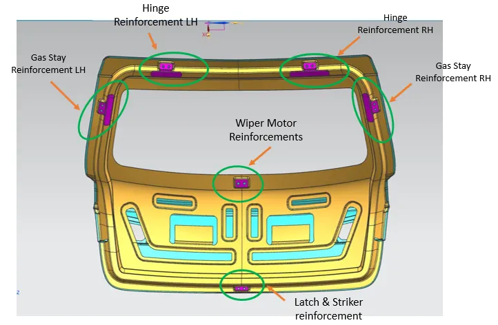
Reinforcement are provided mainly in hinge, Wiper, Gas Stay and latch region. When assemblies are attached to inner panel, strength of that area reduces locally so we add some additional material to increase the strength of the area locally. Thickness of reinforcement material is provided according to the design requirements. In this project, 1.5mm thickness has been given to both latch and hinge reinforcement.
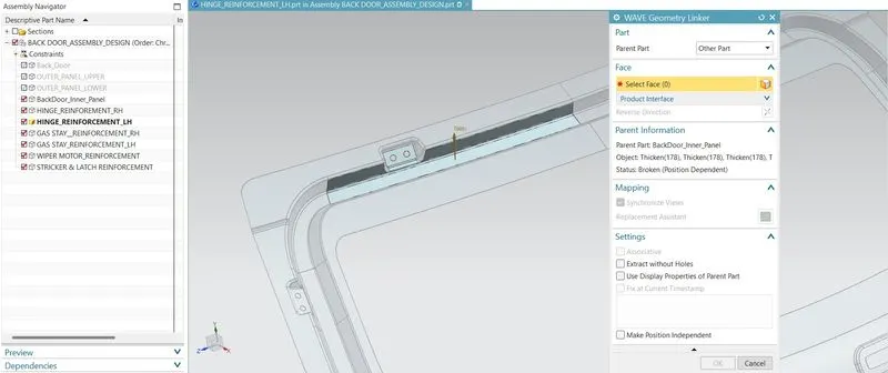
By using the wave geometry linker, the Hinge Mounting faces are been selected and created a liked surfaces for the reinforcemnt.
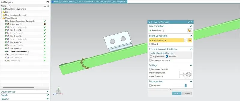
By using the curve on surface command with G0 continuity, the points are created by which the boundary lines are created and trimmed it off rom the reinforcements.
VARIOUS REINFORCEMENTS:
DESIGN DATA FOR HEMMING:
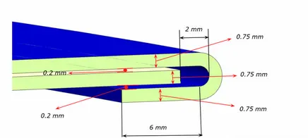
Based on the Design requirement, The hemming processes has been done on the Inner and Outer panel and gap between the Ineer and Outer panel are created @ 0.2 mm.
MEASUREMENTS:
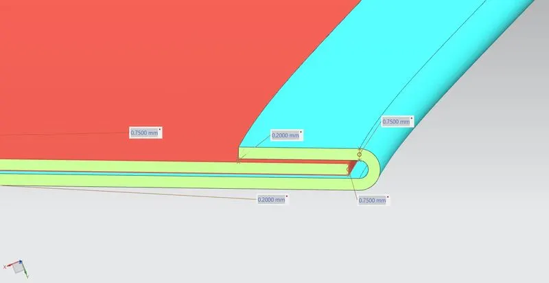
The inner and outer panel are thickned to the thickness of 0.75 mm. and the gap between the panels are provided 0.2 mm.
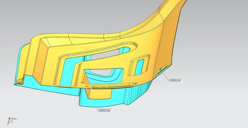
The gap between the Outer panel to the Mastic points are been measured and it to be lie 5 mm distance to make the mastic seals with the outer panel.
RELIEFS:
A bend relief prevents tears from occurring where there is a transition between bends or between a bend and a flat surface. They are a great way to ensure a clean looking part that is free from deformation, burrs, and sharp points where the bend edges terminate. This is doubly important if part is subject to vibration or flexion as the tears and cracks created by unrelieved bends will tend to propagate rapidly. Ultimately, well-designed bend reliefs create a part that is stronger, more stable, and attractive.
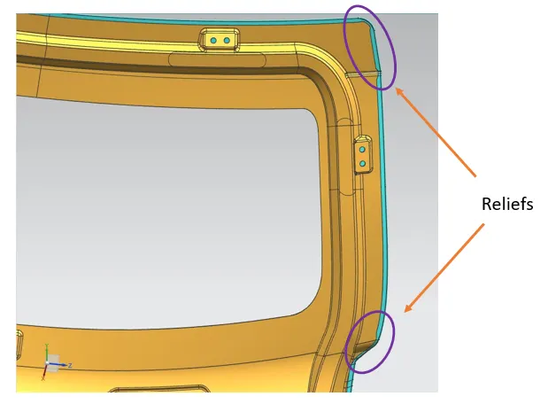
ADVANTAGES OF USING RELIEFS:
- Prevents tearing and deformation of your part caused by a press brake. No tears means the part that’s safer to hold, easier to manufacture, more durable, and will yield a better looking, customer-friendly part when manufacturing is complete
- Separates bent and unbent elements of your part. Isolating the bent portion of your part makes it more durable and attractive
- Ensures forming accuracy. Bend reliefs give the press brake operator some wiggle room with tool placement. Erring on the side of caution by using a wide bend relief will go far to make the press brake operator’s job easier, safer, and more accurate. This can translate to cost savings, particularly when you move to higher volume production, as forming setup and run time will be reduced.
DRAFT ANALYSIS:
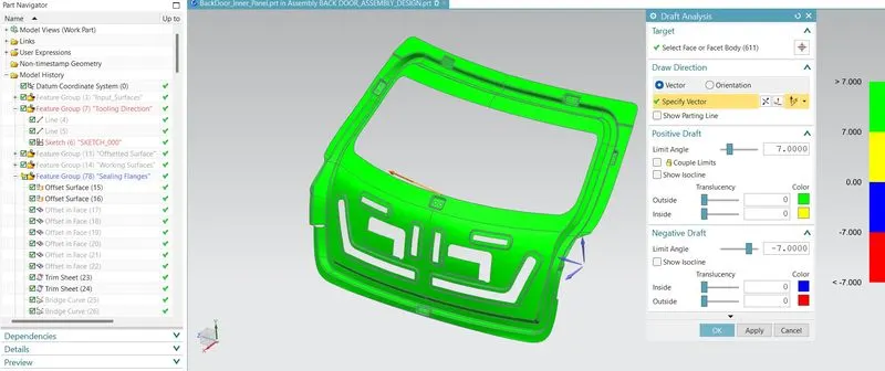
By selecting the respective body faces and the vector as a Tooling Direction, the draft analysis has been done on the Back Door Inner Panel at 7 degerees.
TREE STRUCTURE:
BACKDOOR FINAL ASSEMBLY:
CONCLUSION:
- The Assembly for the Backdoor by developing essential Reinforcements and Embosses are been created.
- The draft on the Reinforcements and Outer upper and Outer Lower Panels are been analyzed.
- The Reinforcements (Hinge Reinforcement, Gas Stay Reinforcement, Latch/Stricker Reinforcements, Wiper Motor Reinforcements) as seperate Parts are created and assembled.
- The backdoor assembly by using the appropriate Design Methodologies are created.
- The Assembly of Backdoor Inner Panel, Outer Panel, Latch, Hinge and the Reinforcements are created.
- The detailed report about the Bckdoor Design by explanationing about Backdoors and its components, Latch Trajectory, Mastic Data, Emboss Definitions are explained in detailed.
- The Various Manufacturing process involved in Creation of Backdoor are explained.