Fender Design
FRONT FENDER DESIGN
AIM:
To Create a Front Fender design using the Skin data provided, also by using the Master section to create a Drip Area and to create a Sill, Bumper, Baffle (Splash), A-Piller Mounts on the Fender.
OBJECTIVE:
- To Create a Front Fender Design Using the Skin data provided.
- To Follow the Master section for creating the Drip Area.
- To Follow the Engineering Standard for creating the Sill, Bumper, Baffle (Splash), A-Piller Mounts on the Fender.
- To Explain about the Fender and its types in detail.
- To Explain about different types of Mounts in the Fender Design and Mounting points created.
- To Create a Fender which follows the Master section for all the Mounting Poing and Tool workability.
INTRODUCTION:
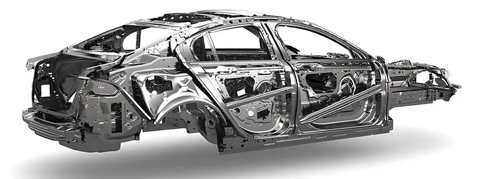
BODY IN WHITE (BIW):
In the Automotive Industry BIW (Body in White) is the common terminology used to mention the car sheet metal welded structure (body shell). Sub-assemblies like Under body, Body side Left Hand Side/ Right Hand Side, Front End, Roof etc. gets welded together by various metal joining process like resistance spot welding, Laser welding, MIG welding to make welded metal shell (Without Door, Trunk-lid / Tailgate) , Fender, Hood) called Body in White. Automotive car shell made before painting is called Body in White.
FENDER :
Fender is a plastic, metal, or rubber curved panel over the wheels on the side of a car, extending from the front bumper of the car to the door. The main purpose of fenders is to keep dirt, mud, and other debris off of the tires and braking system, making them safer and more efficient.
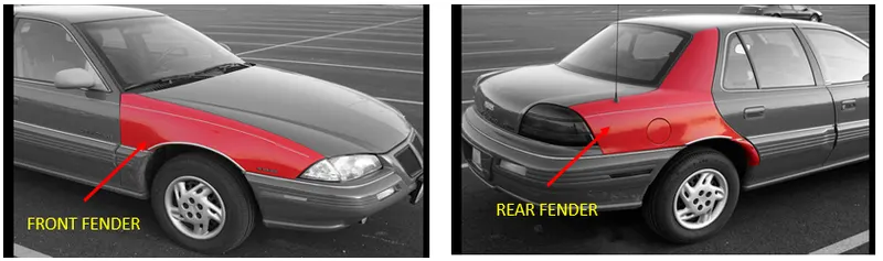
Fenders are attached to the frame of the car, and they come in different styles and sizes.Fenders also help prevent mud, dirt, dust particles, and other liquids from getting thrown in the air while the tires rotate.
TYPES OF FENDER:
The Fender will be over the wheels of the car on the Bumper, They are classified intotwo types,
(1). Full Bumper Type
(2). Half Bumper Type
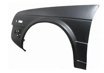
(1). FULL BUMPER TYPE FENDER:
Full Bumper type is traditional type of fender where lot of sheet metal consumption is observed. This type is used in old design of automobiles where it increases the overall weight and thus reduces performance. The maintenance also relatively more due to more surface.
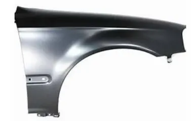
(2). HALF BUMPER TYPE FENDER:
Mainly half bumper type is used in automobiles. In the full bumper, we can only produce one Fender per blank, whereas as a half bumper type we can produce two fenders per blank. It is basically related to scrap management. Half bumper type leads to less wastage of the blank. We are changed from full bumper type to half bumper type to reduce the scrap rate per blank.
MOUNTINGS OF FENDER:
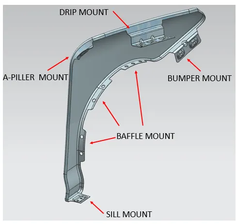
In order to fix the Fender to the respective body panel Areas with the fastners, the Mountings are needed in the Fender to fastening with the respective areas,
There are five Main type of Mountings,
(1). Drip Mounting
(2). Sill Mounting
(3). Bumper Mounting
(4). A-Piller Mounting
(5). Baffle (spalash) Mounting
DIFFERENT MANUFACURING PROCESSES:
The most important design consideration of any component is manufacturing aspect. In sheet metal, the component is manufactured by press tool dies. The Press tool is stamping which includes cutting operations like shearing, piercing etc. and forming operations like bending, Deep drawing, hemming etc.
FORMING PROCESS:
Forming describes the process of transforming the flat metal into another shape by applying force. It is accomplished in one of several ways, depending on the design specifications for the part. With a series of operations, the metal can be altered from a relatively simple shape into a complex one.
DEEP DRAWING:
The deep drawing is used to manufacture a product with seamless, complex shapes. This is tool related manufacturing process where the metal is stretched or extended between two tool halves to create prospective shape.
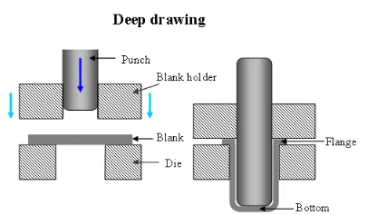
The process involves a punch with a round comer and a die with a large radius. The punch-die clearance is slightly larger than the thickness of the sheet metal to be deep drawn. As the load applied through the punch, the sheet metal is forced to flow radially and sink into the die cavity to form a cup. The process is best suitable for complex shaped problems. Deep drawing is one of the most widely used processes in sheet metal forming. Apart from its use in many other sectors, it is applied in the automotive industry for the manufacturing of car body parts.
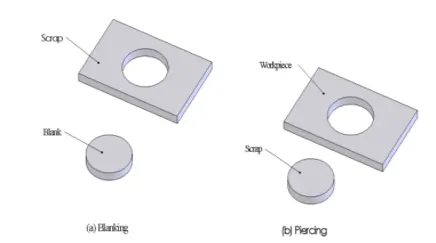
BLANKING AND PIERCING:
Blanking and piercing are the shearing processes in which a punch and die are used to produce parts from coil or sheet stock. The blanking produces the outside features of the component, while piercing produces internal holes or shapes.
EMBOSSING:
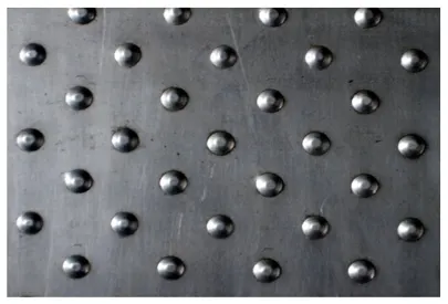
Sheet metal embossing is a stamping process for producing raised or sunken designs or relief in sheet metal. This process can be made by means of matched male and female roller dies, or by passing sheet or a strip of metal between rolls of the desired pattern.
APPLICATIONS OF SHEET METAL STAMPING PROCESS:
- In the stamping process, sheet metal is transformed into complex parts using highly specialized computer-aided drafting and manufacturing programs.
- Sheet metal stamping produces superior, resilient, heavy-duty parts quickly and efficiently.
- The results are so precise, they’re typically more reliable and consistent than manual machining.
MASTER SECTION:
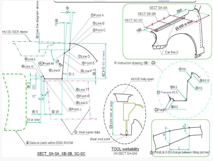
- From the Master Section, the drip area Mounting are been designed on the Front fender skin data's.
- Through the Drip area the fastners are been majorly attached to the Engine compartment area which follows the certian standard.
- From the A Piller Mounting the Drip Mounting are been 300 or less far and also from the Lightning Area the Drip Montin Area should be 150 mm apart from that.
- The rear end point of the front fenders are created by which the tool workability are been easy to handle when the Hood are in open conditions.
INPUTS - SKIN PART:

CREATION OF FENDER DESIGN - DRIP MOUNT AREA
In Fender the Drip Area is connected to the engine compartment through fasteners. It is important mounting for fender therefore lot of design constraints are to be followed while designing the drip area. Clearance should be provided from the front and rear end of the fender.
The Fender Skin data are provived, by following the Master section provided the Drip Area are been created for the Mountings and Various other Mountings are been created.
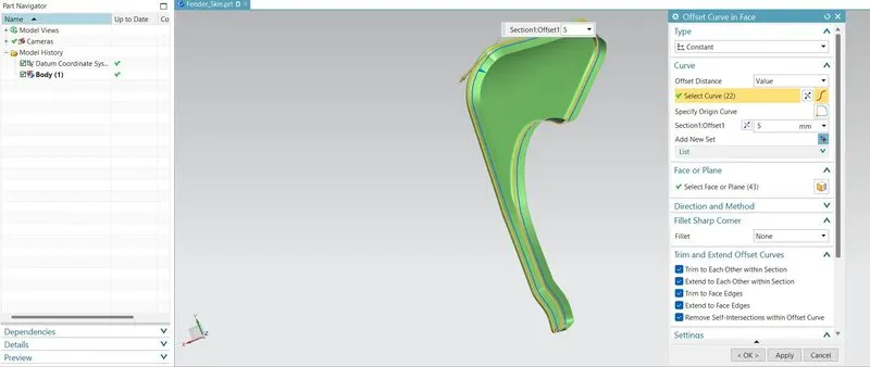
By using the offset curve in face command, the curve by tangent continuty are been selected to offset @ a distance of 5 mm from the origin to trim the extra portions of the flanges in fender.
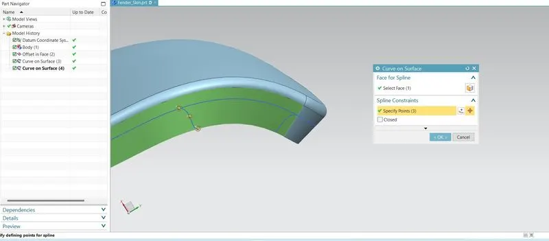
By using the Curve on surface command, the faces are been selcted from which using the spicify points the continuty (G1) spline curve are been created.
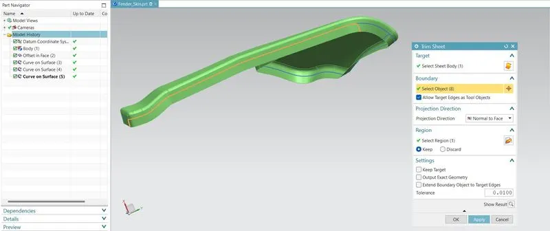
By using the Trim sheet comand the target sheet body are been selected and the Boundary are ben selected with ending at the intersections curves and sheets are been trimmed off.
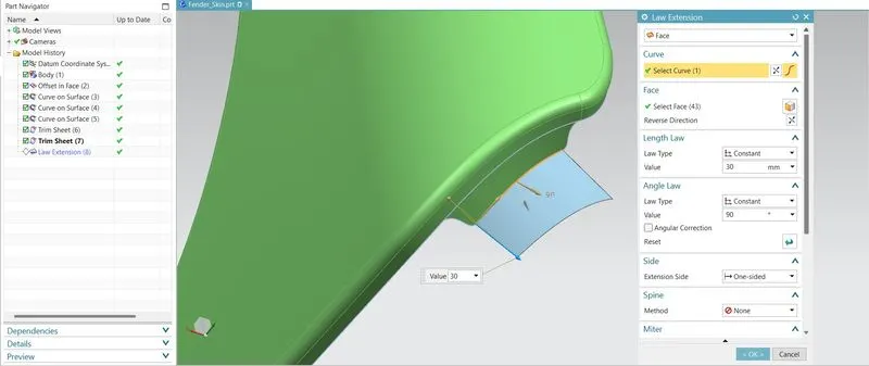
The Law extension command are used to craete a flange sheet perpendicular the curve trimmed off for the creation of A - pilller Mountings.
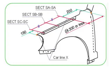
Based on the Master section, from the A-Piller Mount area the plane are created at the distance of 300 or less that that and also from the lightining area from the distance of 150 mm, the plane are been created.
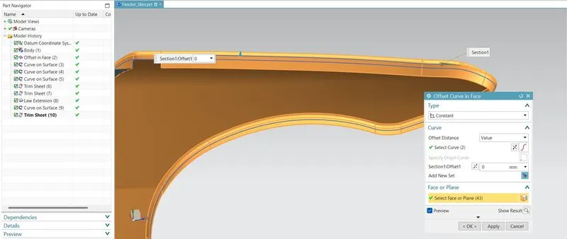
By using the offset curve in face command at the distance of 0 mm, the curve has been created from which the planes are been created for the Drip Mountings.
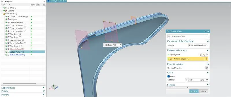
On the cure, the Datum plane are been created to at the distance of 200 mm from the A - Piller Mounting point and at the 150 mm disatance from the Lightning area.
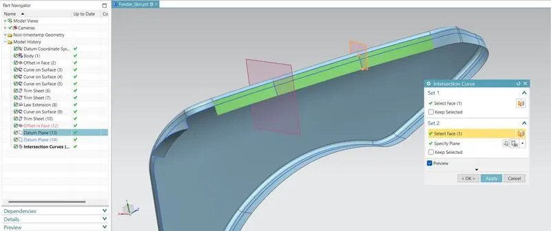
By using the Intersection curve commad the plane and the faces are been selected to create a intersecton line on the selected faces.
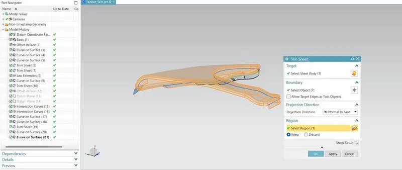
By using the Trim sheet command the target body faces and bondary are been selected to trimm off the region.
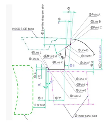
With respect to the respective Master section, the varous flanges on the Mounting Drip area are been created with the respective angles and values provided.
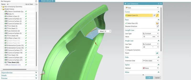
By using the Law Extension, the sheet perpendicular to the selected curve are been created as per the Master section provided.
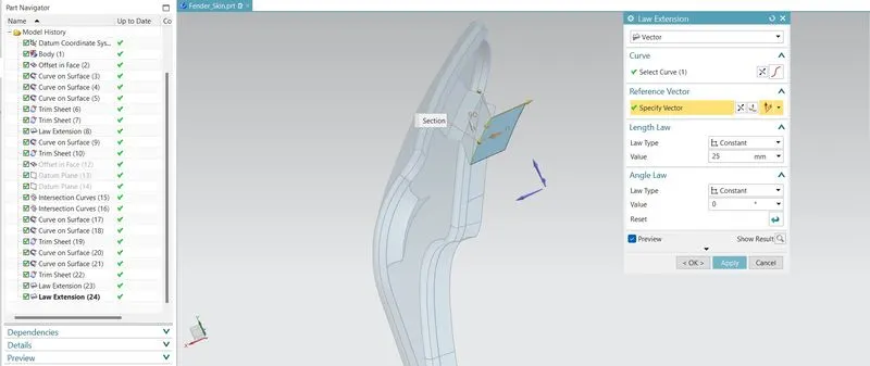
Also, by the specified vector selection sheets base Mounting faces are been created on the selected curves as per the Master sections.
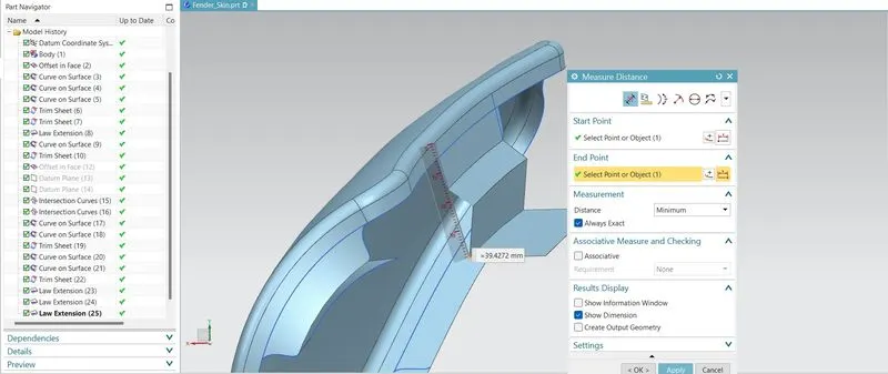
With Reference to the Master section, the distance from the top to the Bottom point are been less than 40 mm and measured accordingly and obsorved as 39.4272 mm.
CALCULATIONS:
For creating the End curved porion on the Drip Mount Area, the respective calculations are been done to find out the values for uisng the Law Extension,
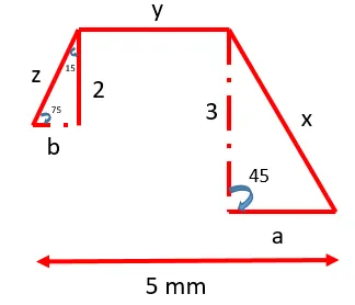
(1). Find X:
`sin (45) = 3/x`
Therefore `x=4.243`
(2). Find a:
`sin(45)=a/4.243`
Therefore `a=3`
(3). Find z:
`sin (75)= 2/z`
Therefore `z=2.070`
(4). Find b:
`sin (15)= b/2.070`
Therefore `b= 0.535`
(5). Find y:
`y=2-0.535=1.46`
Based on the calculation the Drip area flsges are been created at the end portion area.
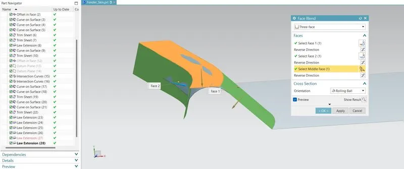
Based on the Master section, edges are been blended to the respective values by selecting the respective faces accordingly.
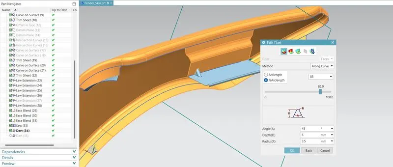
By using the Dart command, the faces are been selected to create a Darts on sides of the walls to strengthen the sheet metal part to overcome the spring back effects.
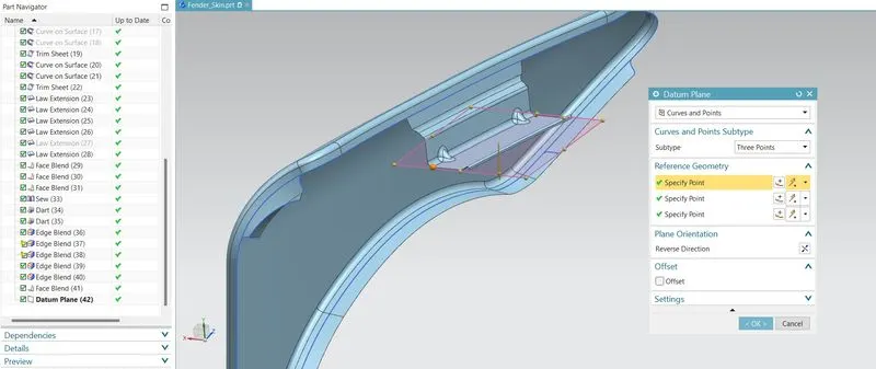
By using the Datum plane, curves and points are been selected with three points and selected accordingly to create a respective plane.
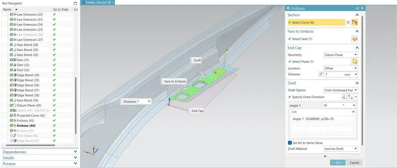
On the respective plane, the sketches are bene drawn and projected along the respective vector, and using the Emboss command the faces and the curves are been selected with the draft angle of 10 deg the Respective embosses are been created.
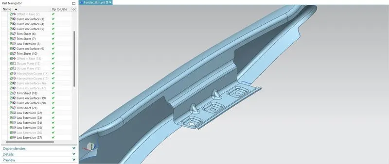
After the Edges are been filleted to the respective radii,the Drip mount area are been created according to the Master section. The Drip Mount area plays an important role in the assembly of Fender with the Casing on the Engine Compartment.
CREATION OF BUMPER MOUNT AREA:
Bumper Mount Area is located to the side of bumper. Bumper mounting area is provided to attach bumper to front fender. Fender is assembled first then bumper is attached by covering the bumper mounting area through fasteners.
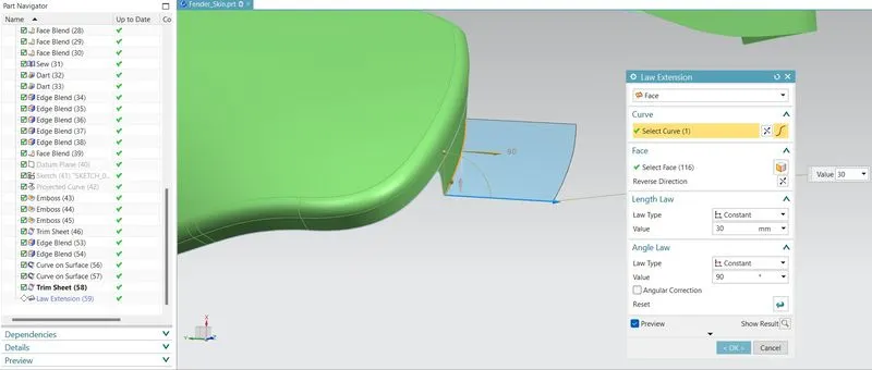
For the Bumper Mount Area the cutout section is created by using the curve on surfaces on the flanges and trimmed off the extra portions. By using the Law extension by single curve the faces are been selected and extended at the draft angle of 10 deg.
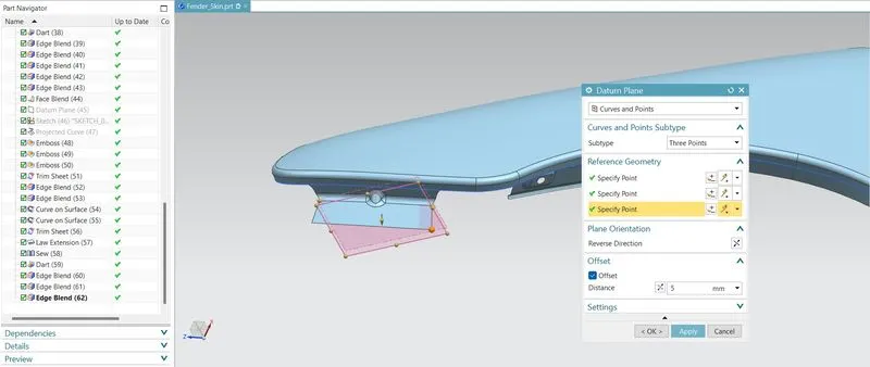
By using the Datum plane commnad, with the sub type of three points, the datum palne has been created from which the 2 -D sketch are been drawn.
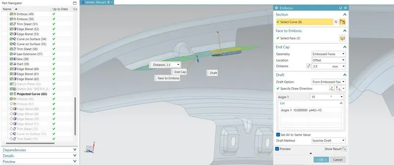
After the creation of 2-D sketch, the sketches are been projected on the surface to create Embossing with the drfat angle of 10 deg.
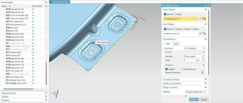
At the end of the Bumper Mount area, the sharp corners are been filleted by uisng the relife. The relifes are used to prevents tears from occurring where there is a transition between bends or between a bend and a flat surface.
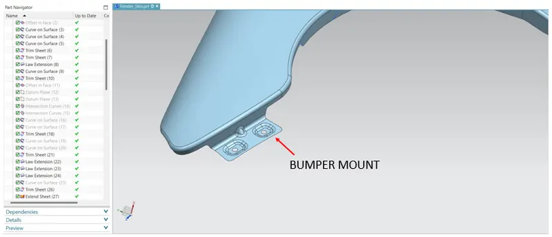
By following the Engineering standard, Bumper mount Area are been created.
CREATION OF BAFFLE MOUNT AREA:
Baffle is a plastic part which is mounted along the wheel arch area. Baffles are mounted on the fender using locking clips.
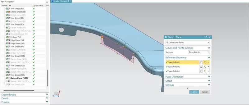
For creating the Baffle Mount Area, the flages and cutouts are been created and using the trimming the extra portions of flanges are been trimed off. By using the curve on surface command teh points are specified as G1 - continuty.
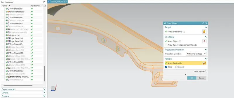
By using the Datum Plane command, the plane are created by three point selection and sketches are been drawn on the respective plane and projected on the surface. and using the trim Seet command the Push pin Holes are been trimmed off from the sheets.
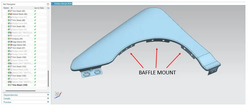
By following the Engineering standards, the Baffle (spalash) mount areas are been created.
CREATION OF A-PILLER MOUNT AREA:
A-Pillar mounting region is located near the cowl which is a plastic area which accommodates the wiper motor and other instruments related to wiper. Fender is connected to the A-Pillar through fasteners. A-Pillar is the foremost pillar of the car, the one that holds the windscreen.
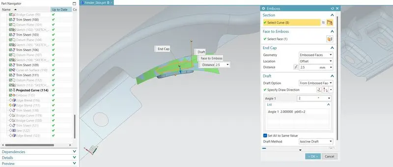
For creating the A- piller Mount Area, the flanges and cutouts are been created and using the trimming the extra portions of flanges are been trimed off. By using the curve on surface command the points are specified as G1 - continuty. By using the Datum plane commnad, with the sub type of three points, the datum palne has been created from which the 2 -D sketch are been drawn and Embossing are created.
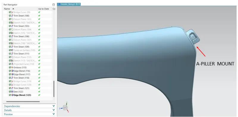
At the end of the A-Piller Mount area, the sharp corners are been filleted by uisng the relife. The relifes are used to prevents tears from occurring where there is a transition between bends or between a bend and a flat surface.
CREATION OF SILL MOUNT AREA:
Sill Mounting is the area at which bottom side of the fender is connected to the bottom part of the vehicle body. It is attached with the fasteners.
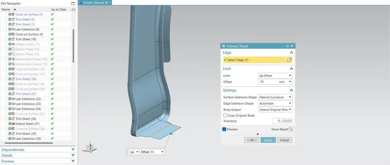
For creating the Sill Mount Area, the flanges and cutouts are been created and using the trimming the extra portions of flanges are been trimed off. By using the curve on surface command the points are specified as G1 - continuty.By using the Extend sheet command the respective single curve by 15 mm.
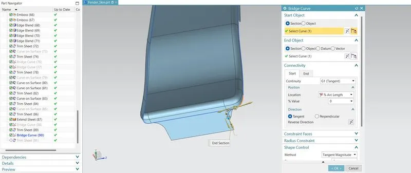
By using the Bridge curev command the sections are been created and end sections are selected to create a Arc lenth at G1 - Continuty.
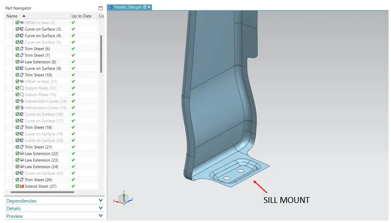
By using the Datum plane commnad, with the sub type of three points, the datum palne has been created from which the 2 -D sketch are been drawn and Embossing are created. By following the Engineering standards, the Sill mount areas are been created.
THICKNING THE FENDER:
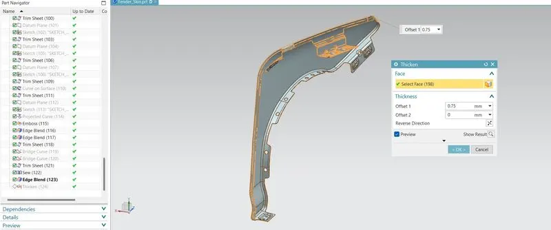
By using the Thicken command, te surface are been Thickne dto 0.75 mm inward, the front fender with Drip, A-Piller, Sill, Bumper and Baffle Mounts are been created.
FENDER DESIGN VARIOUS ORIENTATIONS:
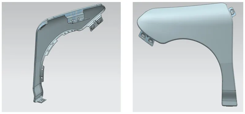
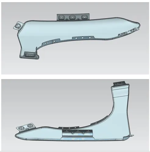
CONCLUSION:
- The Front Fender Design Using the Skin data provided are been created.
- The Master section for creating the Drip Area on the front fender are been followed and Created a Drip Mount Area.
- The Engineering Standard for creating the Sill, Bumper, Buffle (Splash), A-Piller Mounts on the Fender are been followed and created respectibe Mounts.
- The Fender and its types are Expalined in detailed.
- The different types of Mounts in the Fender Design and Mounting points are created.
- The Fender which follows the Master section for all the Mounting Poing and Tool workability are been analyzed and created accordingly.