To plan a structural layout and to create grids using TSD
- Que no. 1 -
- Ans -
- Summrization of user interface in TSD as follows.
- Project Workspace - The project workspace area is central control are of drawing. It is clear white space used for drawing our structure. We can add different levels, sub models and sub structures. We can access the project work space by opening the TEKLA structural designer software and the clicking of new option and start the drawing.
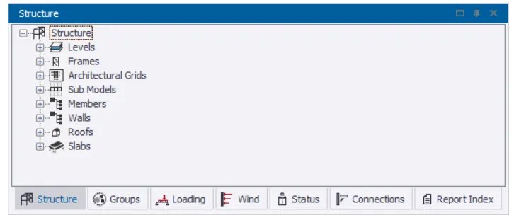
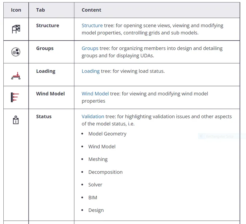
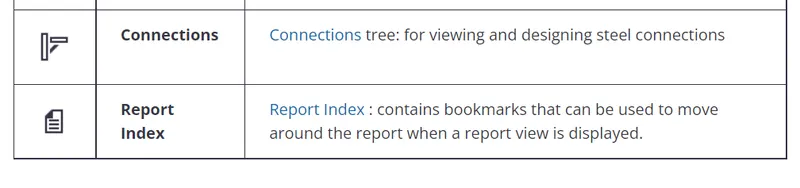
- Scene Content - We the help of scene content option we can manage the control level of the information to be displayed in each scene view. We can do this by switching items on/off in the scene content dialog.
- Create two scene views - We can create a two scene views in TEKLA structural designer software. The function helps us in displaying some content and members in defferent part for easy analysis and evaluation. It can display the structure, sub structure, individual memebers seperately in 3D and some of other remaining parts in 2D.
- Loading drop list- How to access - The loading drop list is located at bottom of window and has downward arrow. With thw help of arrow buttons we can nevigate across the options. It has many functions such as we can select or specify a specific load case and we can also add loads.
- Properties window - It is located at left side of window which is enclosed in rectangular box. We have many sub options like structure, loading, groups, status, connections and wind. We can see the commands and change the properties according to our requirement.
- Que no. 2 -
- Ans -
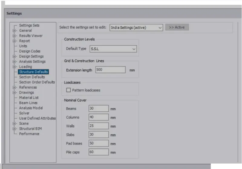
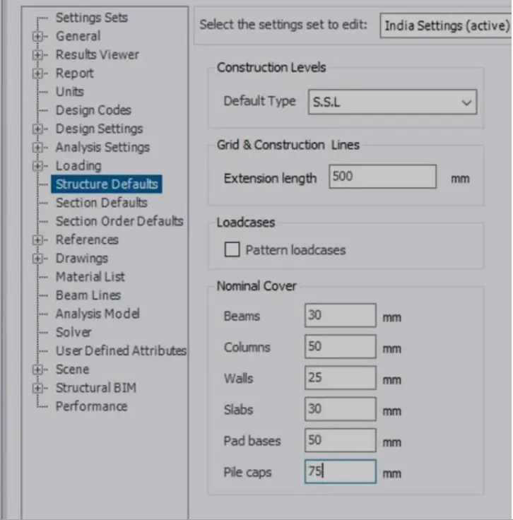
- Aim - Create a new file in TSD and set up the settings for a steel building to have member grade FE 410 and concrete grade M 30 as per IS codes. The covers for members to be as per following input
- Tools used -
- File.
- Settings.
- Structure defaults.
- Manage property sets.
- Process -
- Open a new file.
- Under file manu select settings.
- Settings dialog box appears.
- In that select structure defaults and set all the values accordingly to our requirements.
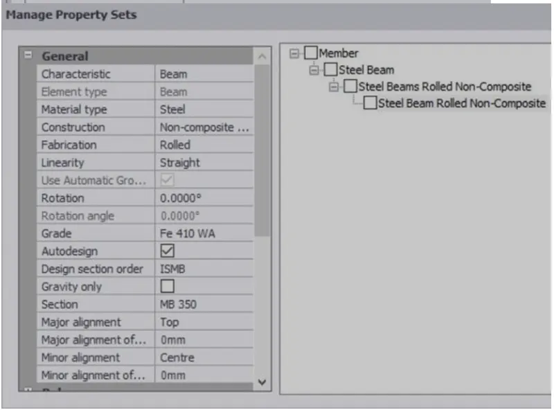
- Under file menu select manage property sets.
- Manage propety sets dialog box appears.
- In that select new ---> memebers ----> steel beam.
- Result -
- Thus with the above steps a new TSD file is created and we can set the settings required.
- Que no. 3 -
- Ans -
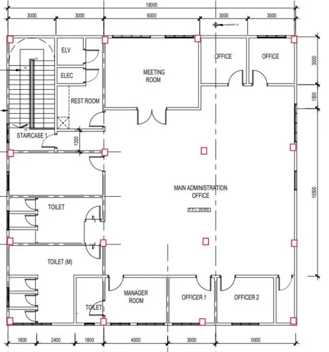
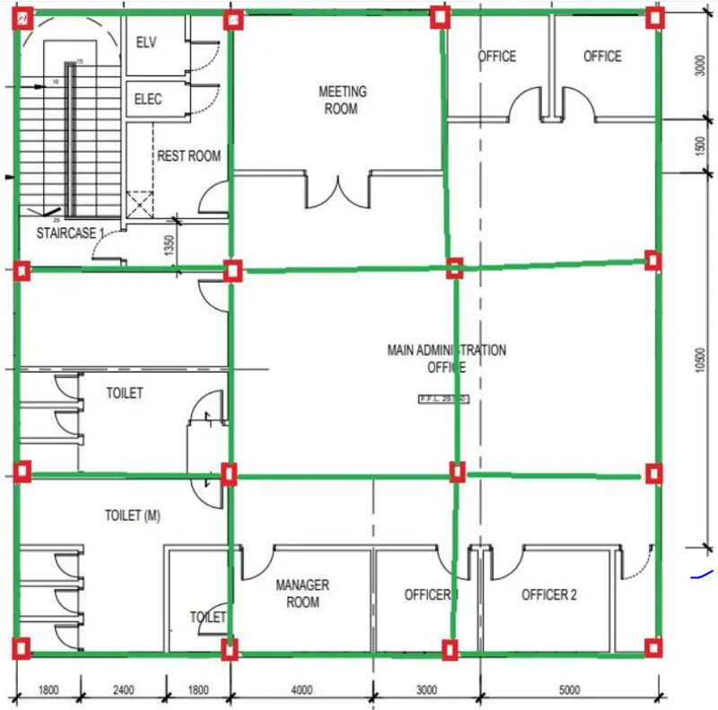
- Attachment 1 - Placement of beams and columns (Columns in red and beams in green colour)
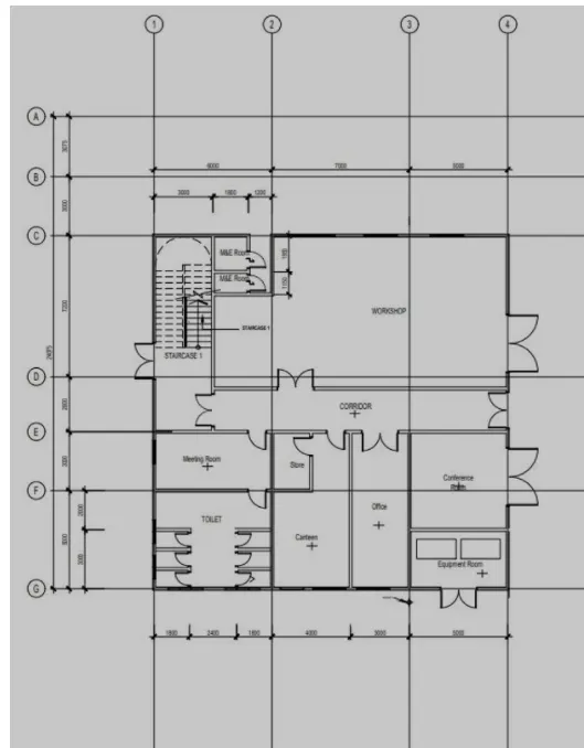
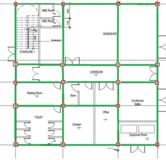
- Attachment 1.1 - Placement of columns and beams (Columns in red and beams in green colour)
- Attachment 1.2 - Placement of columns and beams (Columns in red and beams in green colour)
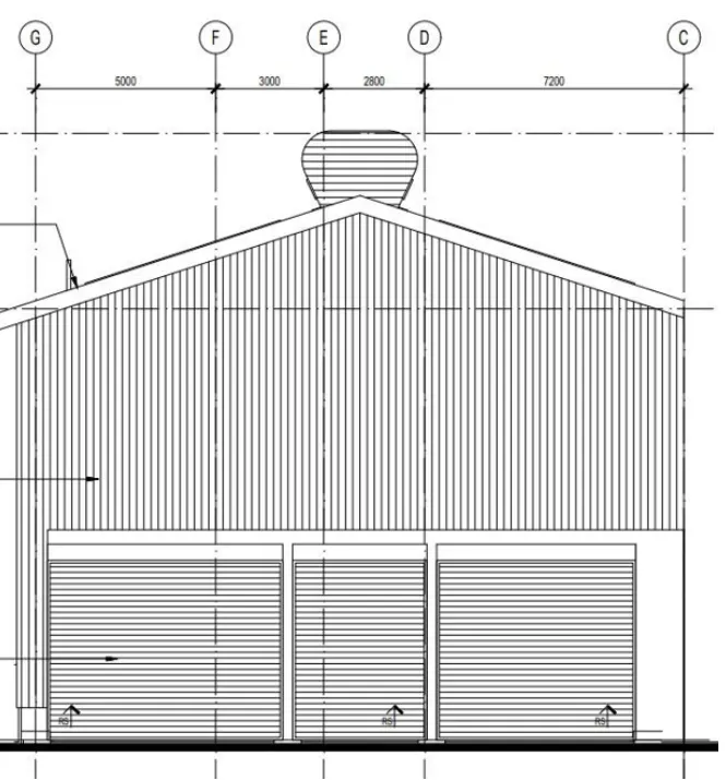
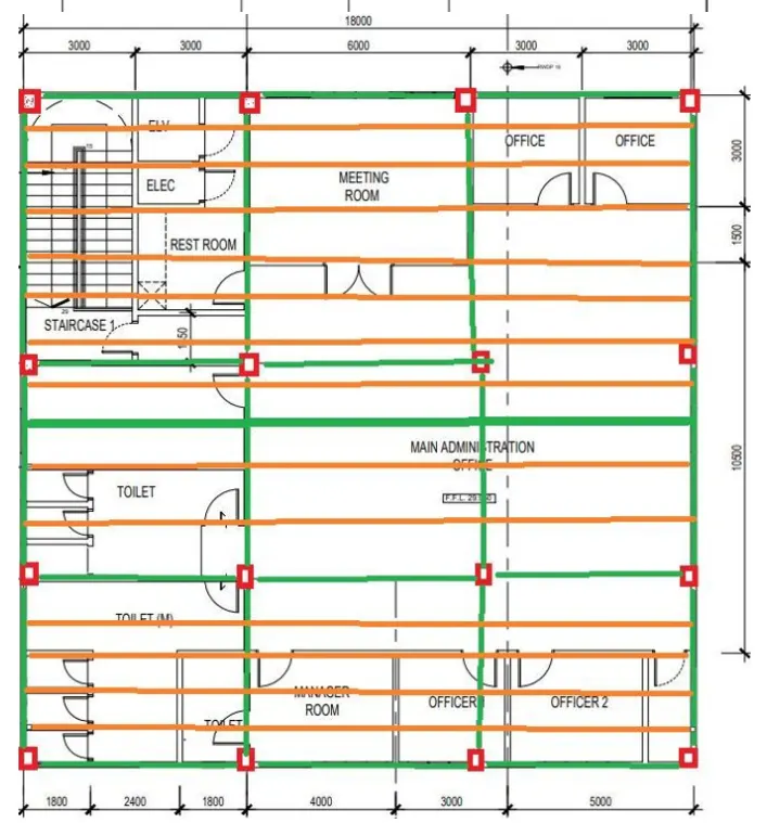
- Que no.4 -
- Ans -
- Aim - Model grid lines and construction levels as per attachment 1. 1.1 and 1.2. All dimension are in mm.
- Tools used -
- Levels.
- model.
- file.
- grid line.
- parallel (quick).
- Process -
- Open new file.
- Select level option under structure tool.
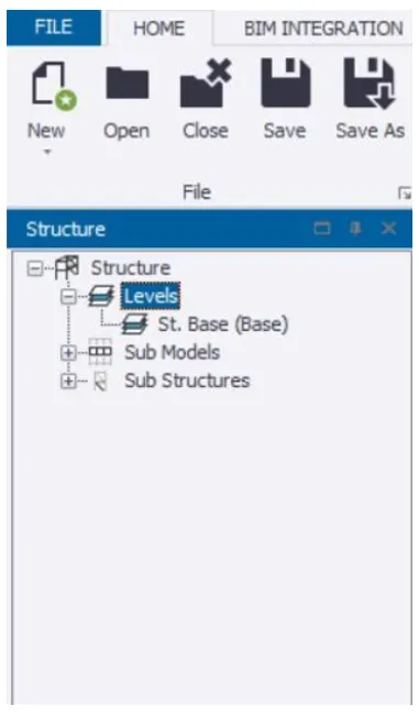
- Levels dialog box appears.
- Give specific name to each and every level and specify height for each level.
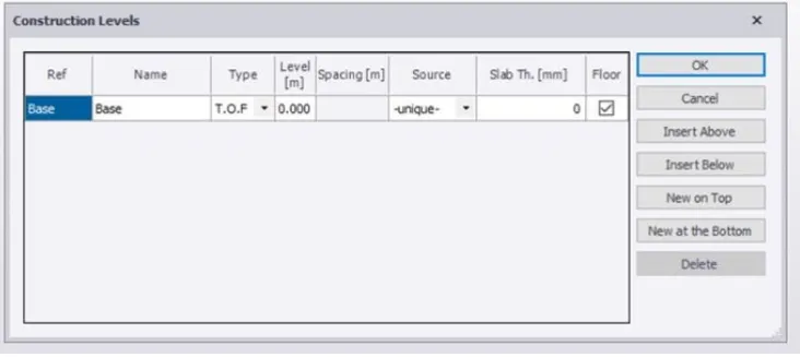
- Then click on OK.
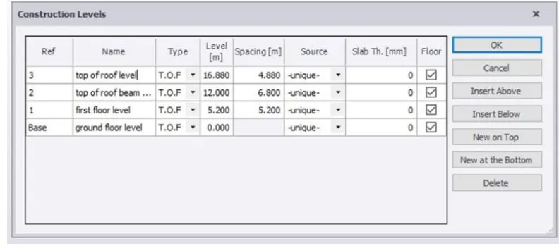
- The particular levels are assigned and created with the particular heights mentioned.
- Click on model tab and select grid option.
- Click on any face on the workspace and draw a grid line.
- With same option continue to draw all the horizontal and vertical grid lines.
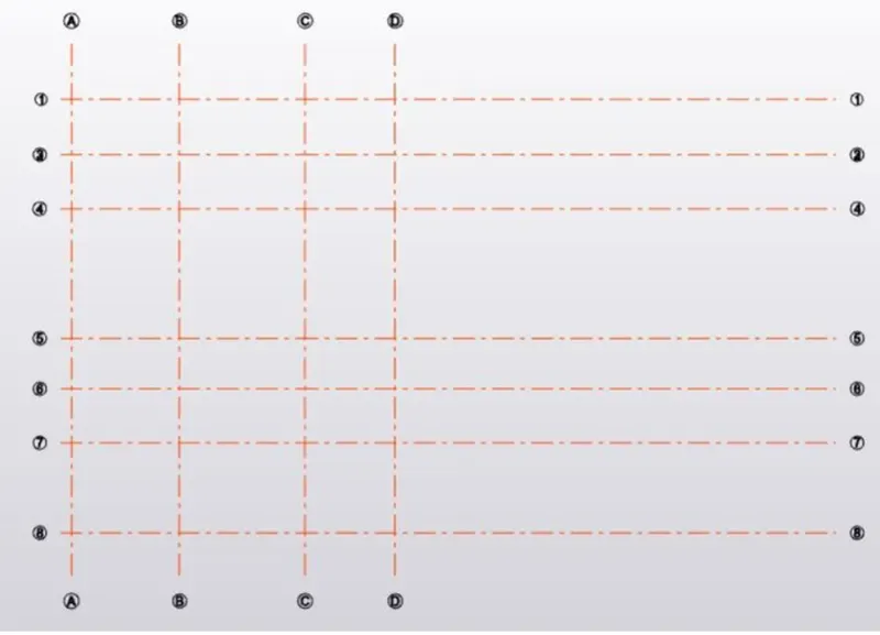
- Result -
- With the above following steps we can create the construction levels along with model grid lines.