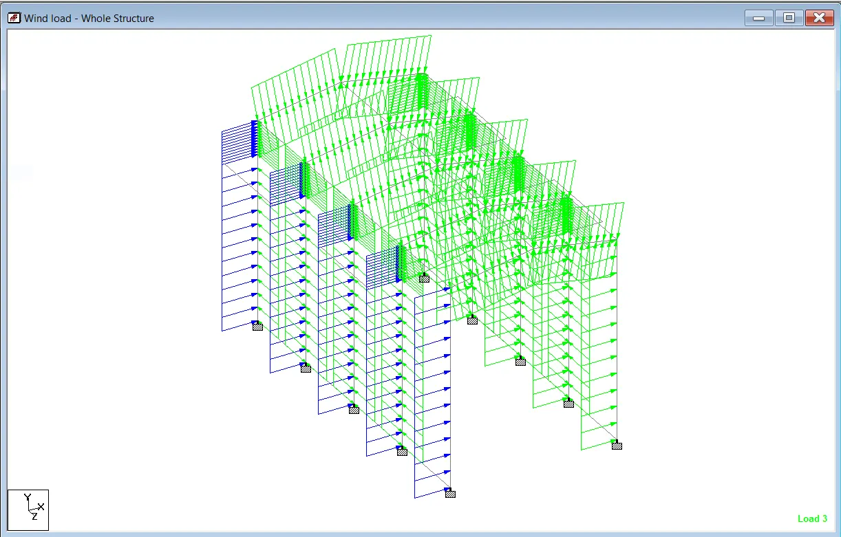
Week 10 Challenge
- Question no 1.
- Ans -
- Files and snaps are attached below.
- Aim - To calculate number of purlins and girts for building.
- Introduction - We can find the numbers of purlins and girts as per given data. Here we model the structure in staad and analysis is done as per given data.
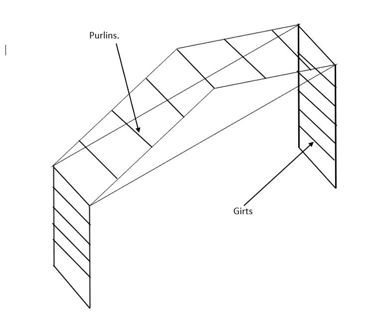
- Purlins - Purlin is a horizontal beam or bar used for structural support in structures, most often below the roof. Purlins are supported either by the building's rafters or its walls. A roof's purlins support the roof Deck's weight. Purlins carry the roof deck or sheathing loads and are supported by large rafters and/or building walls, steel beams, etc. Purlins pass roof loads to the major structural elements supporting the roof; the form and arrangement of purlins is a design factor that depends on the instance of roof loads as well as the limiting sheeting lengths to use. In the final analysis, local building codes should always be understood and implemented in the design of structure.
- Types of purlins -
- Steel purlin.
- C shaped purlin.
- Z shaped purlin.
- Girts - The girt is commonly used as a stabilizing element to the primary structure (e.g. column, post). Wall cladding fastened to the girt, or a discrete bracing system which includes the girt, can provide shear resistance, in the plane of the wall, along the length of the primary member.
- Since the girts are normally fastened to, or near, the exterior flange of a column, stability braces may be installed at a girt to resist rotation of the unsupported, inner flange of the primary member. The girt system must be competent and adequately stiff to provide the required stabilizing resistance in addition to its role as a wall panel support. Girts are stabilized by (sag) rods/angles/straps and by the wall cladding.
- Stabilizing rods are discrete brace members to prevent rotation of an unsupported flange of the girt. Sheet metal wall panels are usually considered to provide lateral bracing to the connected, typically exterior flange along the length of the girt. Under restricted circumstances, sheet metal wall panels are also capable of providing rotational restraint to the girt section.
- Given -
- Rafter span = 50 m.
- Bay spacing = 8 m.
- Roof slope = 1 in 10.
- Height of column = 12 m.
- Brick wall height = 2 m.
- Purlin spacing = 1.2 m.
- Girt spacing = 1.5 m.
- Process -
- Create model of structure with given data in staad.
- Open staad -> create file -> define nodes and beams -> create model - > join purlins and girts.
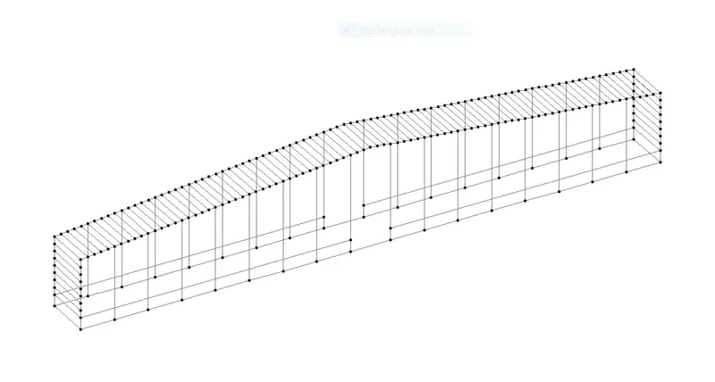
- Roof slope = 1/10 = inverse of tan 0.1 = 5.71 m.
- Middle column height = 50 x cos 5.71 = 50 m.
- Also mid height of node = 50 x tan 5.71 = 5 m.
- No. of purlins = 50 / 1.2 = 42 no.
- No. of guirts = 12-2 = 10/1.5 = 7 no.
- Draw and assign the columns as per given condition.
- Provide brick wall at 2.0 m height.
- Question no 2.
- Ans -
- Files and snaps are attached below.
- Aim - To taper the beam with BMD envelope given.
- Introduction - Here we can taper the beam as per given data. Tapering means to check the beam is safe or fail to carry the loading condition.
- Taper of beam - A tapered beam subjected to a tip bending load will be analyzed in order to predict the
distributions of stress and displacement in the beam. - In common structural practices, member tapering is a combination of both web and flange tapering in depth, width, and thickness.
- To reflect the general tapering of all elements of a tapered member, the existing taper concept, which is based on the web depth taper ratio, is to be extended to cater for any kinds of practical tapering configurations.
- BMD envelope - Computing envelopes can be one of the most tedious tasks of structural analysis for statically indeterminate structural elements.
- The process requires determining the arrangement of live loads for maximum effects, analyzing the structure for the resulting load arrangements, and then comparing the results to get the envelope values.
- The process may lead to errors if the engineer is not diligent enough to analyze all the appropriate load arrangements. The process can also lead to an explosion of load arrangements in the interest of thoroughness.
- BMD envelope is process of loading on structure to get clearly idea about member is pass or fail after analysis in staad.
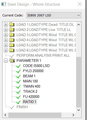
- Utility ratio - Utility ratio is the ratio of Actual Load on member to the capacity of member, if it exceeds more than 1 then load on member will be greater than its capacity and member gets collapsed.
- As per IS 800 we get utility ratio value up to 1. Also in staad analysis and design of member we take ratio as 1. To apply utility ratio as a design parameter to check section is paas or fail.
- Given - Attachment of file.
- Process -
- Download the file.
- Check all conditions are assigned completely.
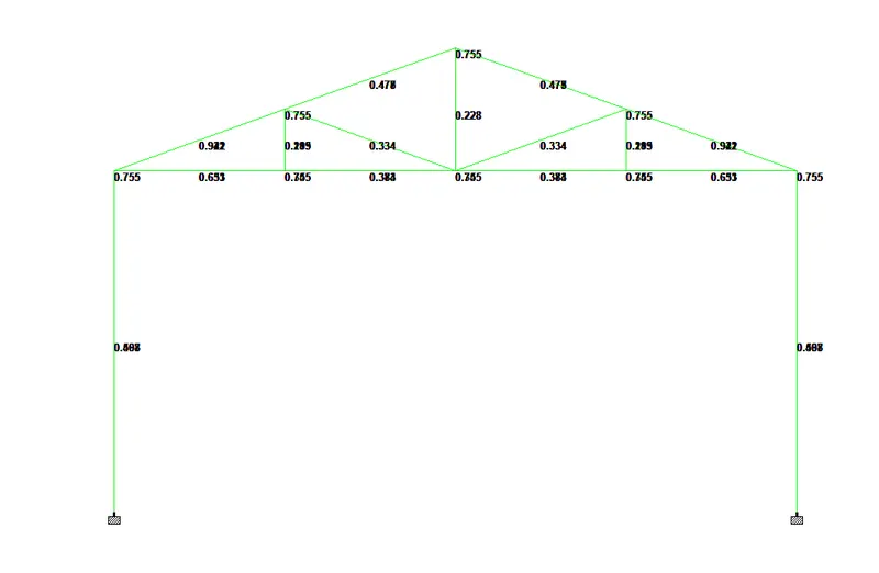
- Taper the beam as per conditions such as reduce the size of section R1.
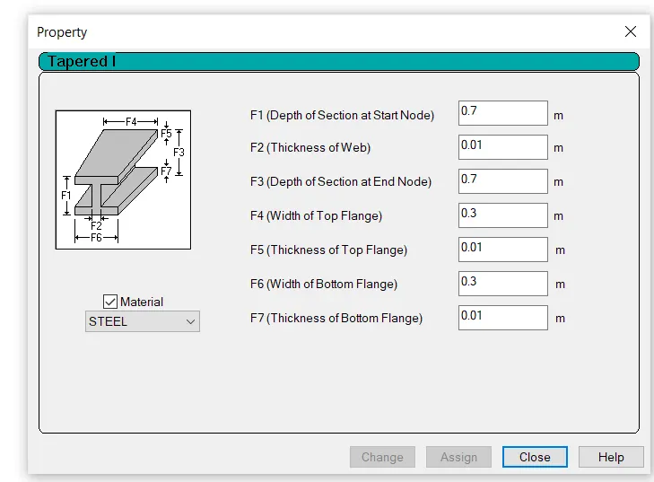
- Go to design check design parameters such as utility ratio, check code etc.
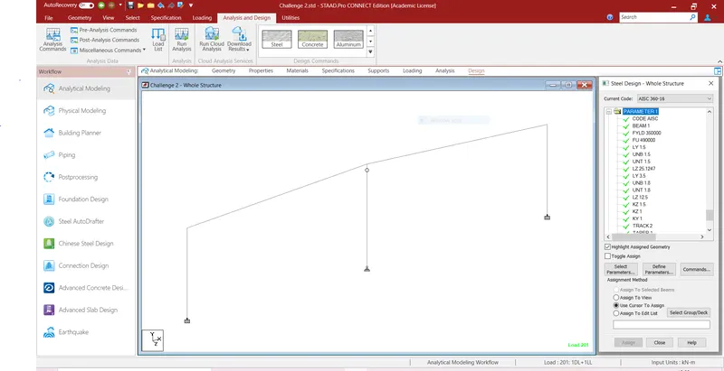
- After run the analysis and check BMD envelope.
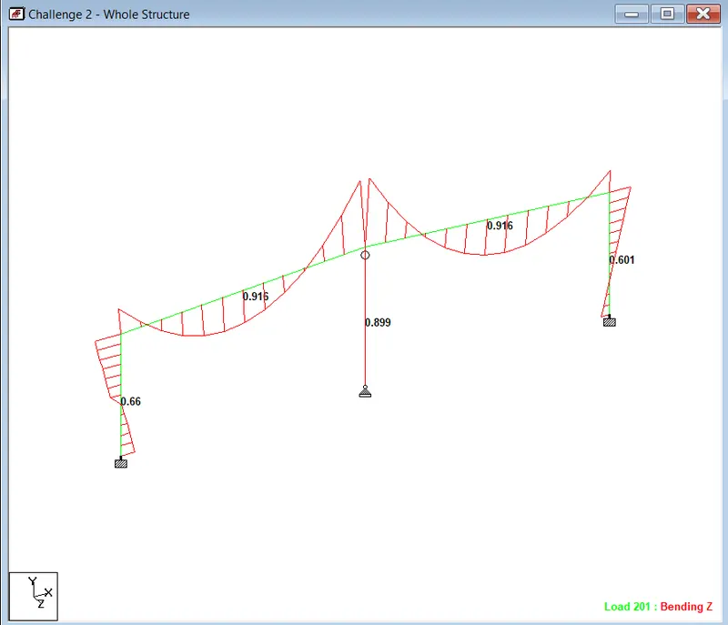
- We seen that utility ratio are whithin limits means less than 1.
- Question no 4.
- Ans -
- Files and snaps are attached below.
- Aim - To find support reaction for given load.
- Introduction - Here the given is that mono sloped structure. We find the support reactions. It is a reaction on which the support acts.
- Support - A support prevent translation of body in given direction, a force is developed on the body in that direction
- Reactions - The forces and moments exerted on an objects by its support called as reactions.
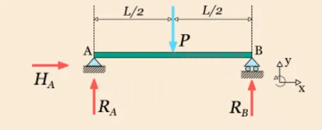
- Given -
- Mono sloped structure.
- Angle of slope = 20 degree.
- Width = 10 m.
- Length = 30 m.
- Bay spacing = 6 m.
- No wall sheeting (fully open all around).
- Apply Dead load, Live Load & Wind load on the structure and find the support reaction.
- Also perform static check if the total load applied on the structure is captured in support reaction for each load case.
- Self Weight factor = 1.1.
- Roof Sheet loading = 0.5 KN/m^2.
- Purlin load = 6 KN/m^2.
- Live Load on Roof = 1.5 KN/m^2.
- Wind Load on rafter (Pressure) = 2 KN/m^2.
- Assume column height = 5 m.
- Process -
- Create model of structure.
- Open staad -> Create new file -> define nodes and beams.
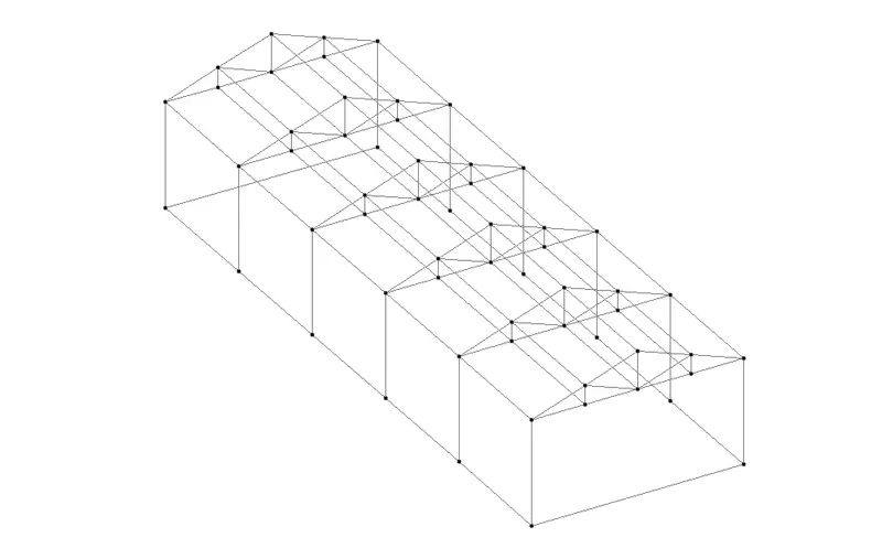
- Mid heigth of roof = 5 x tan20 = 1.81 m.
- Go to Translation -> apply bay specing -> ok.
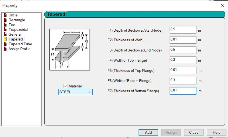
- Go to properties -> define section - > tapered section choose -> put all data.
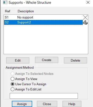
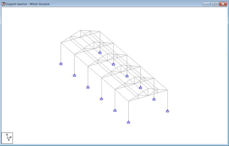
- Go to support -> create support -> apply ok.
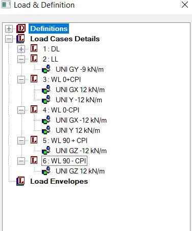
- Go to loading -> Add dead load, live load & wind load -> go to case details add and assign load to structure.
- Roof sheeting load = 0.5 KN/m^2.
- Purlin load = 6 KN/m^2.
- Total Dead load = 6 + 0.5 = 6.5 KN/m^2 = 6.5 x 6 = 39 KN/m.
- Live load = 1.5 KN/m^2 = 1.5 x 6 = 9.0 KN/m.
- Wind load = 2 KN/m^2 = 2 x 6 = 12 KN/m.
- Go to run the analysis.
- Check support reactions.
- Go to design -> choose IS 800 LSD -> add and assign design parameters -> run analysis -> check results.
- Question no 3.
- Ans -
- Below attached files and snaps.
- Aim - To determining Wind load for certain category and condition as per IS 875 Part 3:2015.
- Introduction - Here we find the wind load of structure. We can use the IS 875 part 3. Wind load is special type of load. Normally wind load takes place into account when industrial structure is constructed. For RCC construction there is wind load taken into account when multystoried structure constructed such as G+10, G+20 buildings.
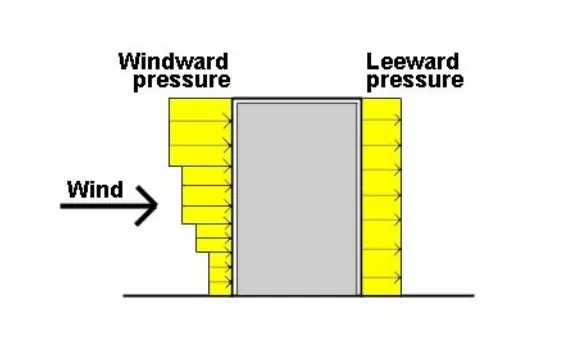
- Wind load - Pressure applied due to the wind on a structure is called wind load. This load gets distributed throughout the surface area of structure.
- The magnitude of this load increases as height of structure increases i.e. Taller structures has more effect due to the wind than shorter structures.
- Wind Load is directly related to wind speed. The higher the speed, higher the wind load and vice versa. So wind speed of that area plays an important role for wind load on a structure.
- Wind speed at 10 m height above mean ground level is known as Basic Wind Speed. It is based on peak gust velocity averaged for a short time interval of about 3 seconds and corresponds to mean height above ground level in an open terrain.
- It is obtained by multiplying basic wind speed with 3 coefficients related to different factors as below -
- Risk level
- Terrain roughness, height and size of structure
- Local topography
- Types of wind load -
- Uplift Wind Load. Uplift Wind Load is an upwards force of the wind that would affect roof structures or similar horizontal structures in a building, such as canopies or awnings.
- Shear Wind Load.
- Lateral Wind Load.
- Given -
- Industrial plan 10 x 5 dimensions.
- Height of column = 6 m.
- Building situated in chennai.
- Assume wall opening as 15 %.
- So 6 x 0.15 = 0.9 m. = 1 m.
- So Wall openings = 6 - 1 = 5 m.
- Bay spacing = 2.5m.
- assume angle of slope = 10 degree.
- Process -
- Define nodes and beams -> create model.
- Go to Translation -> apply bay specing -> ok.
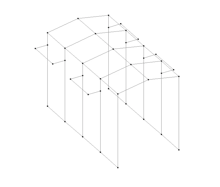
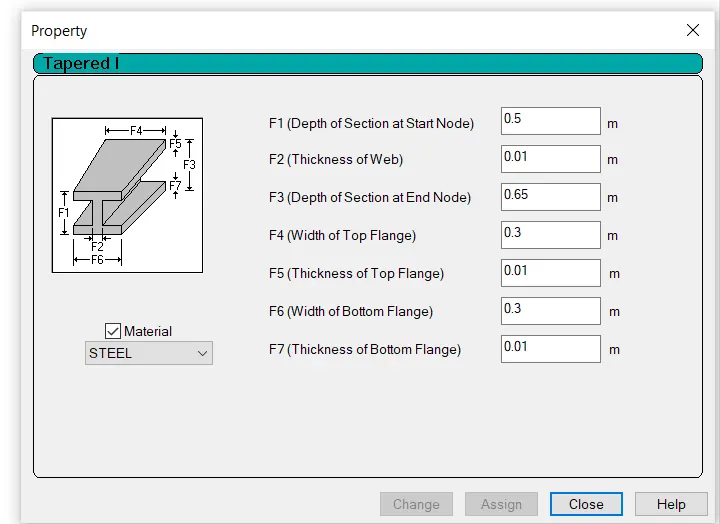
- Go to properties -> define section - > tapered section choose -> put all data.
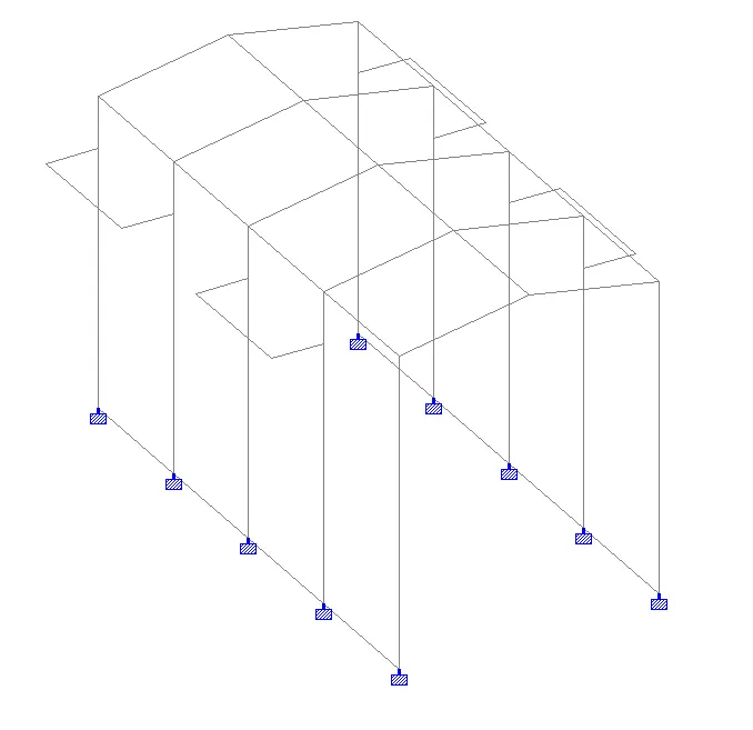
- Go to support -> create support -> apply ok.
- Go to loading -> Add dead load, live load & wind load -> go to case details add and assign load to structure.
- Dead load = 5 KN/m^2.
- Live load = 5 KN/m^2
- Wind load as per IS 875 Part 3.
- Loacation - Channai.
- Basic wind speed = 50 m/s.
- Probability factor K1 = 1.
- Terrain roughness and height factor = K2 = 1.
- Topography factor = K3 = 1.
- The importance factor for cyclonic region = K4 = 1.15.
- Design wind speed = Vb x K1 x K2 x K3 x K4.
- Design wind speed = 50 x 1 x1 x 1 x 1.15.
- Design wind speed = 57.5 m/s.
- Wind pressure = 0.6 x 57.5^2.
- Wind pressure = 1.984 KN/m^2.
- Wind directionality factor kd = 1.
- Area averaging factor Ka = 0.83.
- Combination factor Kc = 0.9.
- Design wind pressure = 1.984 x 1 x 0.83 x 0.9.
- Design wind pressure = 1.482 KN/m^2. = 1.482 x 6 = 8.89 KN/m.
- Internal pressure coefficiant = +/- 0.5.
- External pressure coefficiant =
0 degree 0 degree 90 degree 90 degree EF GH EG FH -0.9 -0.4 -0.8 -0.4