Creating Architectural and Structural model with 3D rendering using REVIT
- Question no.1
- Ans -
- Aim - To select the type of structure and build it.
- Introduction - Here we use three types of structures such as multi unit residential apartment, office buildings, school.
- We can draw the any one structure above the options.
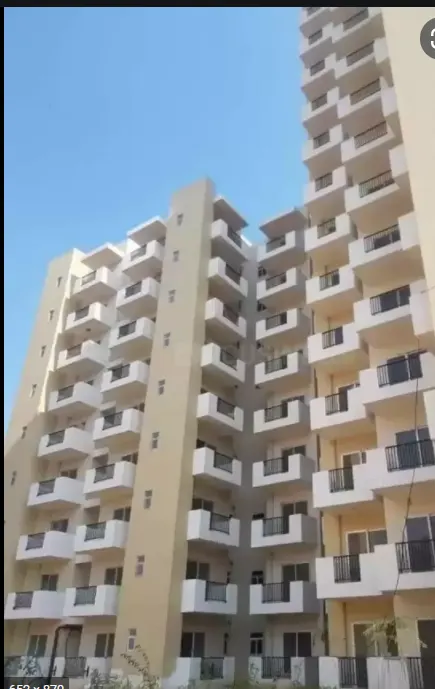
- Multi unit residential apartment - is a classification of housing where multiple separate housing units for residential inhabitants are contained within one building or several buildings within one complex. Units can be next to each other (side-by-side units), or stacked on top of each other (top and bottom units).
- A common form is an apartment building. Many intentional communities incorporate multifamily residences, such as in cohousing projects. Sometimes units in a multifamily residential building are condominiums, where typically the units are owned individually rather than leased from a single apartment building owner.
- Office building - An office is a space where an organizations employees perform administrative work in order to support and realize objects and goals of the organization. The primary purpose of an office building is to provide a workplace and working environment primarily for administrative and managerial workers. These workers usually occupy set areas within the office building, and usually are provided with desks, PCs and other equipment they may need within these areas.
- An office building will be divided into sections for different companies or may be dedicated to one company. In either case, each company will typically have a reception area, one or several meeting rooms, singular or open-plan offices, as well as toilets. Many office buildings also have kitchen facilities and a staff room, where workers can have lunch or take a short break. Many office spaces are now also serviced office spaces, which means that those occupying a space or building can share facilities.

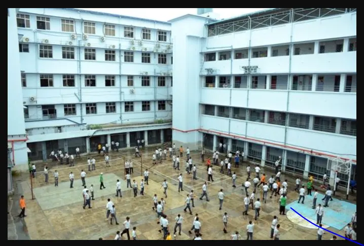
- School buildings - School buildings means any building in which any of the instruction, extracurricular activities, or training provided by a school is conducted, whether or not any instruction, extracurricular activities, or training provided by the school is being conducted in the school building at the time a criminal offense is committed. Having space and natural light should be an absolute given in a school building.
- It should be welcoming and uplifting, providing a sense of ownership and pride for pupils and staff. Research has been carried out over the years on the impact of well designed buildings and it’s proved hard to measure, in terms of its impact on educational attainment, low pupil truancy, better staff retention and productivity, or perhaps a combination of all these factors.
- Results - I want to build a multi unit residential apartment from the above structures.
- Question no.2
- Ans -
- Aim - To Assume reasonable assumptions for geographic and location details for your project modeling.
- Introduction - Here we use the National building code (NBC) guidelines to build our model. National building code (NBC) provides provisions for safety and servicebility requirements. NBC also provides different area measurement guidelines. National Building code is a document containing standardized requirement for the design & construction of most types of apartments in india.
- Although codes may sometimes seem fussy, they are the result of years of experience and testing. Building codes exist to protect the public’s health, safety and welfare. National Building Codes (NBC) regulate building construction & building use in order to protect the health, safety & welfare of the occupant. You must always take the correct precautionary measures to assure the safety of your family members. The National Building Code (NBC) is now a national instrument that will guide the regulations for construction activity. It contains all the important aspects relevant for the safe and orderly building development.
- Results -
- Assumptions made for geographical and location details of my project and modelling requirements from NBC :
- My project is in residential area.
- Road width in front of apaerment is 60'.
- My project is in plain area.
- Area measures should be under NBC rules.
- The height of building should not exceed 1.5 times the width of road.
- Fire safety also provided as per NBC rules.
- Question no.3
- Ans -
- Aim - To include component based on multi unit residential appartment To use structural model for include the components such as foundation, beam, column etc.
- Introduction - Here we use the structural model. In structural model we draw the components such as foundations, beams, columns, roof, floor, elevator and stair. These components are used to design the structural model. These components gives the appropriate behaviour of the model. In structure we draw only framing system. Other families such as chair, sofa, bed are not include in this model.
- Structural columns - Use the structural column tools to add vertical load-bearing elements to building models.
- Structural beams - Use beams tools to add load-bearing structural elements to building models.
- Trusses - Use the Truss tool to add a truss to your building model according to the layout and other parameters specified in the selected truss family type.
- Foundations - Create foundations for the building model using isolated foundations, wall foundations, and foundation slabs.
- There different types of foundations we use isolated/wall/matt foundation.
-
Create foundations for the building model using isolated foundations, wall foundations, and foundation slabs.
- Structure tab Foundation panel
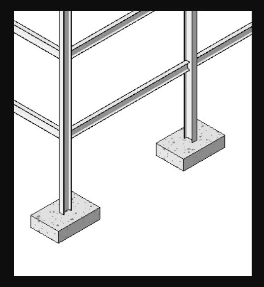
 (Isolated).
 - Use the Structural Foundation: Isolated tool to place a footing beneath a structural column.
- Structure tab Foundation panel
 (Wall).
 - Use the Structural Foundation: Wall tool to place a wall foundation beneath a structural wall. Select a bearing or retaining wall foundation type from the Type Selector.
- Structure tab Foundation panel
 (Slab).
 - Use the Structural Foundation: Slab tool to sketch a foundation for a model.
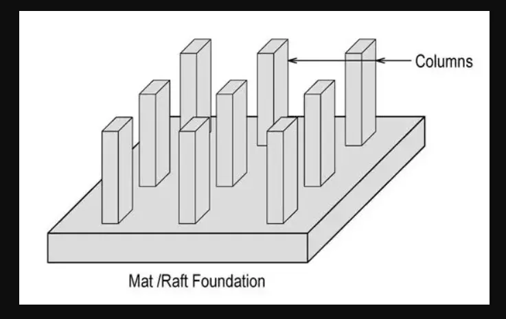
- Matt foundation - A raft or mat foundation is a large continuous rectangular or circular concrete slab that carries the entire load of the superstructure and spreads it over the whole area beneath the building. It is considered as one type of shallow foundation and is useful in controlling the differential settlement.
- Structural floors - Use the structural floor tool to add structural floors to a building model.
- Tools used -
- Structural tools used -
- Grids.
- Levels.
- Columns.
- Foundation.
- Beams.
- Floor.
- Shafts.
- Process -
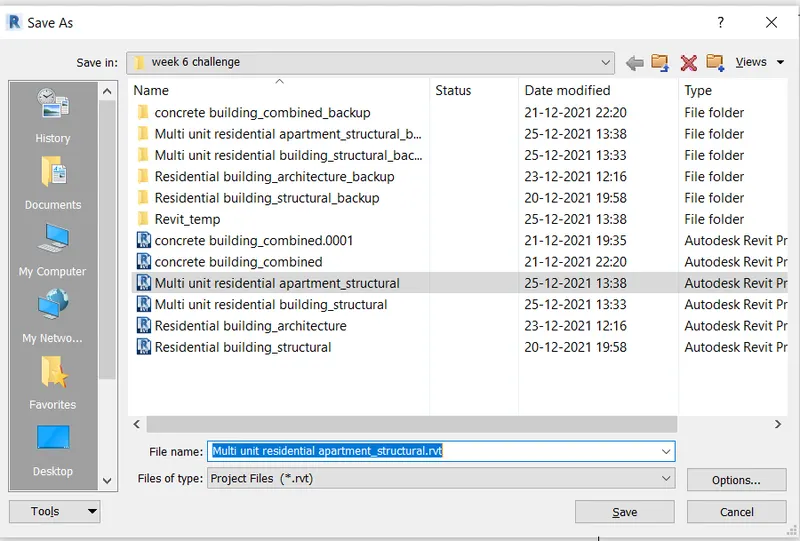
- Open the structural model created in week 6 which has specify coordinates as a 0'0".
- Save the file with appropriate name.
- Step 1 -
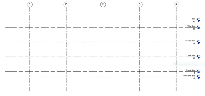
- Go to elevation and click on any of them.(east).
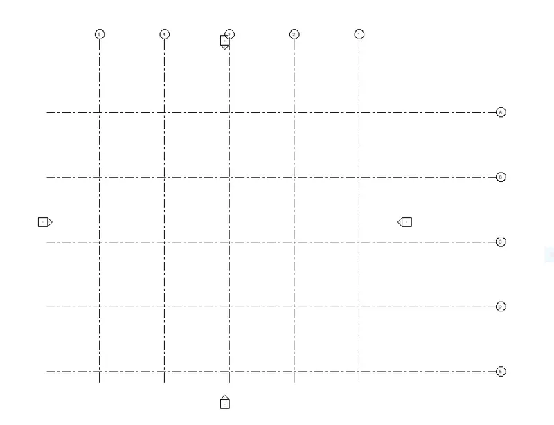
- Select levels in structural model.
- Select grids in structural tab.
- Draw grids transverse and horizontal and name them accordingly.
- Draw required levels for the building with offset 12' and foundation of 5'.
- Name them as ground floor, foundation, first etc.
- Step 2 -
- Under structural tab click on columns.
- Place the columns as required.
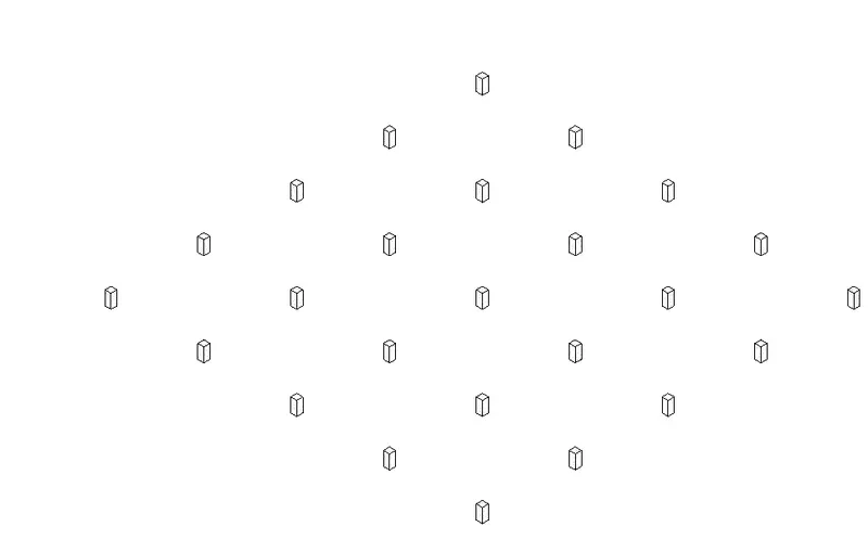
- Draw the foundation, slab, and beams and save project to central life.
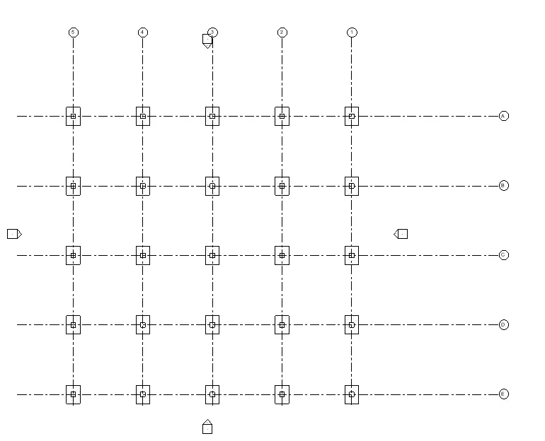
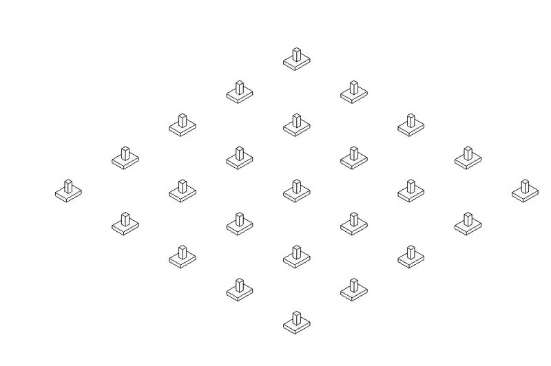
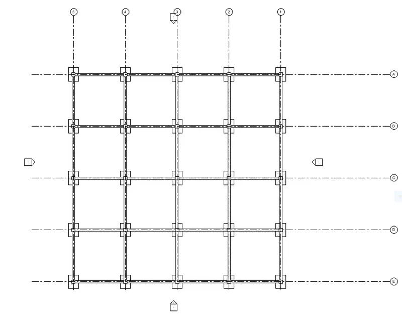
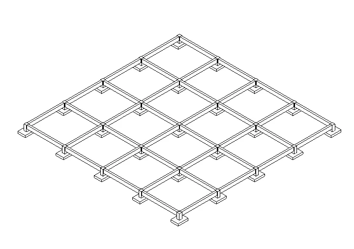
- Step 3 -
- Select the whole plan view created and copy it.
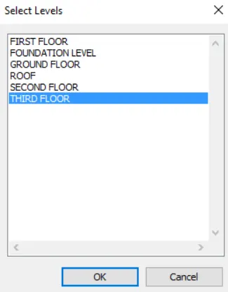
- Paste it with the help of alligned to selected levels to different levels.
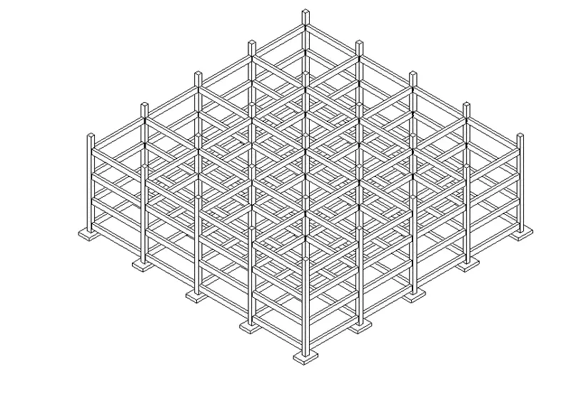
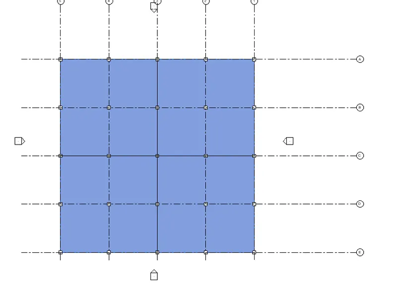
- Click on floor command and draw floor to ground floor.
- Copy the floor from ground floor and add it to other levels.
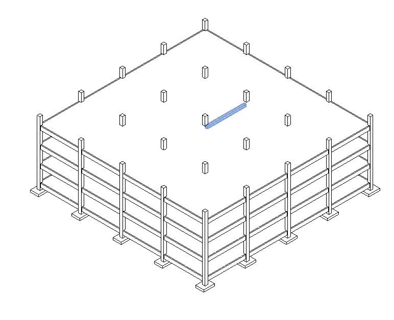
- Step 4 -
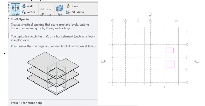
- Select shaft command.
- Add it in the required place.
- Result -
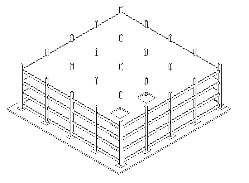
- Hence the structural model of residential unit appartment has been created and following components are added.
- a.Foundation – Isolated/Wall/Matt Foundation.
b.Columns.
c.Beams Connected to Columns.
d.Roof Framing/Truss.
e.Floor/Decks.
f.Floor Openings for Elevators and Stairs. - Question no.4
- Ans -
- Aim - To include components in multi unit residential apartment in architectural model.
- Introduction - Here we use the architectural model. In architectural model we draw the components such as interior and exterior walls, details of rooms, stairs and elevators, glass panels. These components are used to design the structural model. These components gives the appropriate behaviour of the model. In structure we draw only framing system. Other families such as chair, sofa, bed, trees, topographic etc. are not include in this model.
- Architecture model - An architectural model is a type of scale model – a physical representation of a structure – built to study aspects of an architectural design or to communicate design ideas. Depending on the purpose, models can be made from a variety of materials, including blocks, paper, and wood, and at a variety of scales.
-
Wall - Use a Wall tool to create a non-bearing wall or a structural wall in the building model. Non-bearing walls: Click
 (Wall: Architectural) on the
 -
Architecture tabBuild panelWall drop-down.
- Structure tabStructure panelWall drop-down.
- Doors - Use the Doors tool to place a door in a wall. Select a door type from the Type Selector.
- Windows - Use the Windows tool to place windows in a wall or skylights in a roof. Select a window type from the Type Selector.
- Components - Components are used to model building elements that are usually delivered and installed on site, such as furniture and plumbing fixtures.
- Roof - Create a roof from a building footprint or an extrusion.
- Floors - Use the Floor tool to create level, sloped, or multi-layer floors.
- Stairs - Create a stair by assembling components for common runs, landings, and supports.
- Rooms - Create rooms in a plan view with the Room tool, or add them to a schedule to be placed in the model later.
- Architectural design is a way of expression. While a picture is worth a thousand words, a well-executed 3d Architecture Model is worth a million words. It ties the sense of space, context of the site, and materiality into a singular piece.
- Topographic - Topographic models express site levels and contours. While every architecture model needs a flat base, topographic models act as one. No land on earth is flat. Thus, topographic models are used to analyze the site levels, drainage as it helps the architects in the earlier stage of the design and understanding of the site.
- Tools used -
- Architectural -
- Copy monitor.
- Walls.
- Partition walls.
- Load family.
- Roof.
- Ceilings.
- Staircase.
- Railings.
- Process -
- Opent the architectural file that has been created in week 6 in which architectural and structural are combined.
- Select the copy monitor and copy all the grids from structural file.
- Step 1 -
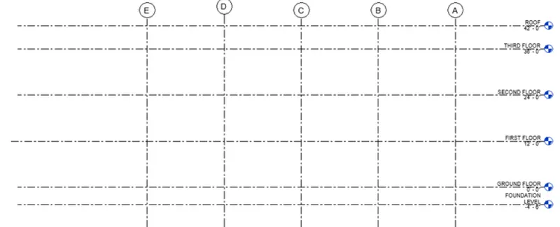
- Go to elevation click on east elevation view.
- Click on levels and add levels as required.
- Step 2 -
- Click on walls under architectural tab.
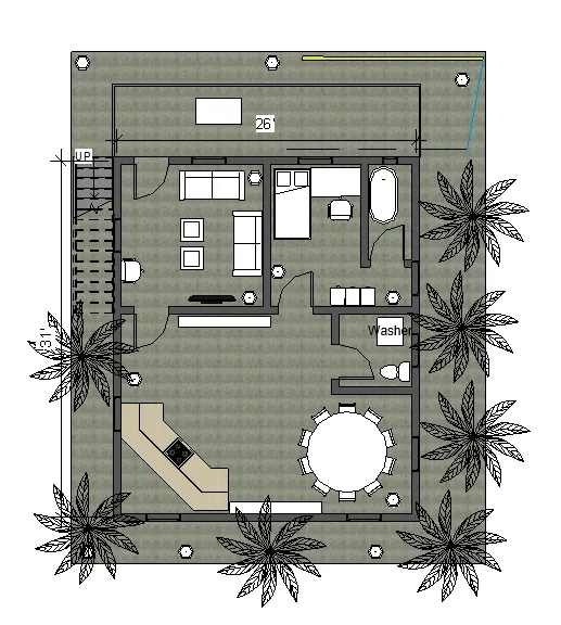
- Draw the plan as required with proper dimensions.
- Add interior partion walls to size rooms.
- Add components from load family.
- E.g. - Chair, beds, kitchen tools, lightning, plumbing fixtures etc.
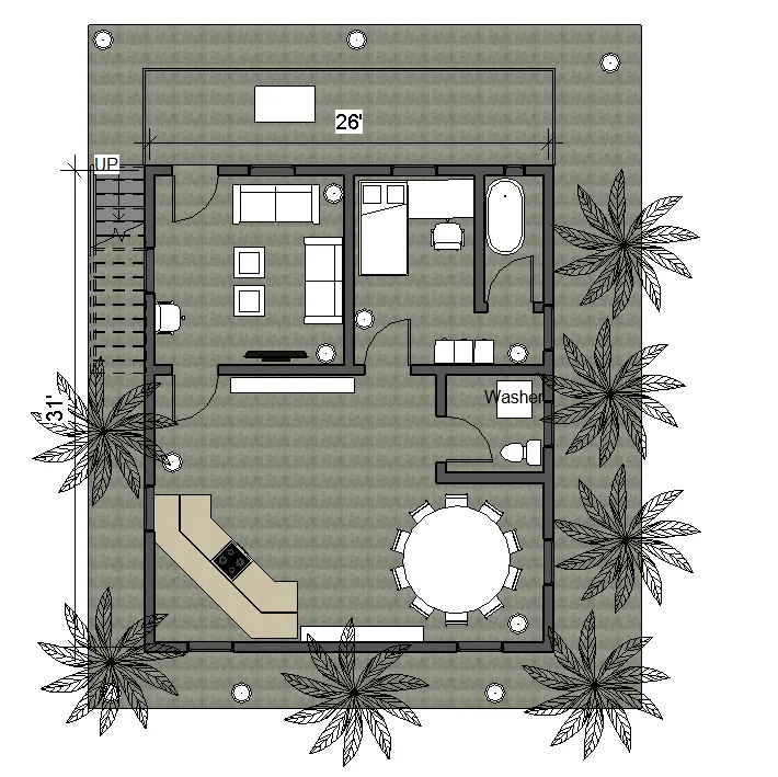
- Add the exterior lightning, planting, parking etc. to make it more realistic.
- Railings are added from architectural tab.
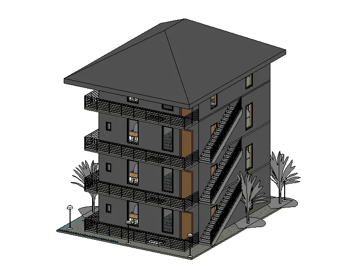
- Staircase, trees, components are added as mentioned.
- Results -
- Hence residential unit building is added with following mentioned components.
- Question no.5
- Ans -
- Aim - To provide architectural and in sheet templated included with floors, elevation, sections.
- Introduction - Here we can do the architecture and structure model set by annotations, elevations and sections.
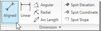
- Floor plans with annotation - Annotation is a very important component in your design. Doesn’t matter if you model it in 3D, you will still need to plot it to 2D drawing. And you need to provide information with annotations. There are many types of annotations in Revit, like dimensions, tags, building elevation symbols, sections symbols, etc. Some annotations added automatically when you created a view. Now let’s discuss about dimensions.
- Elevations -
- [STEP 1] Open the project, and open [Level 1] floor plan.
- [STEP 2] Click [Elevation] from [View] tab, under [Create] panel.
- [STEP 3] Click the [Properties] palette > select Interior Elevation, the symbol will be updated.
- [STEP 4] Hover over your plan.
- [STEP 5] Select the elevation tag.
- Open a plan view.
- Click View tabCreate panelElevation drop-down
 (Elevation).
The cursor appears with the elevation symbol.
- (Optional) In the Type Selector, select a view type from the list, or click Edit Type to modify an existing view type or create a new view type.
- Place the cursor near a wall, and click to place the elevation symbol.
Note: As you move the cursor, you can press Tab to change the position of the arrowhead. The arrowhead snaps to perpendicular walls.
- To set different interior elevation views, highlight the square shape of the elevation symbol, and click.
The elevation symbol displays with check box options for creating views, as the following image shows.
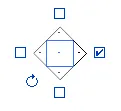 Tip: The rotation control is useful for aligning to angled elements in the plan.
 - Select the check boxes to indicate where you want to create elevation views.
- Click away from the elevation symbol to hide the check boxes.
- Highlight an arrowhead on the symbol to select it.
- Click the arrowhead once to view the clip plane:

Elevation symbol with clip plane
The end points of clip planes snap and join to walls. You can resize the width of the elevation by dragging the blue controls. If the blue controls do not display in the view, select the clip plane and click Modify Views tabElement panelElement Properties. In the Instance Properties dialog, select the Crop View parameter, and click OK.
- Sections -
- Select the section tool and place the cursor at the starting point of the section and drag through the model or family. Click when you reach the endpoint of the section. The section line and the crop region appear and are selected. If desired, resize the crop region by dragging the blue controls. The depth of the section view changes accordingly. Click Modify or press Esc to exit the Section tool. To open the section view, double-click the section header, or select the section view from the Sections grouping of the Project Browser. The section view changes when the design changes or the section line is moved.
- By simply using the section tool you can select the location, orientation and extents of a section view. Revit will automatically process all objects that are cut through and all objects that may be seen within the view, ensuring nothing is missed.
- Open a plan, section, elevation, or detail view.
- Click View tabCreate panel
 (Section).
 - (Optional) In the Type Selector, select a view type from the list, or click Edit Type to modify an existing view type or create a new view type.
- Place the cursor at the starting point of the section, and drag through the model or family.
Note: You can snap a section line parallel or perpendicular to a non-orthogonal datum or wall. Snapping to a wall is available in plan views.
- Click when you reach the end point of the section. The section line and the crop region appear and are selected.
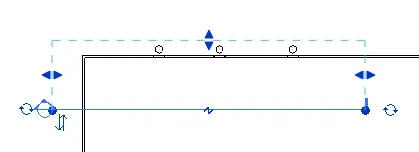
- If desired, resize the crop region by dragging the blue controls. The depth of the section view changes accordingly.
- Click Modify or press Esc to exit the Section tool.
- Tools used -
- View.
- Sheet template.
- Load families.
- Edit sheets.
- Place view.
- Process -
- Go to view tab.
- Click on sheet template.
- Rename the sheet as such with name of the view to be shown.
- For architectural model add the views to sheets templates.
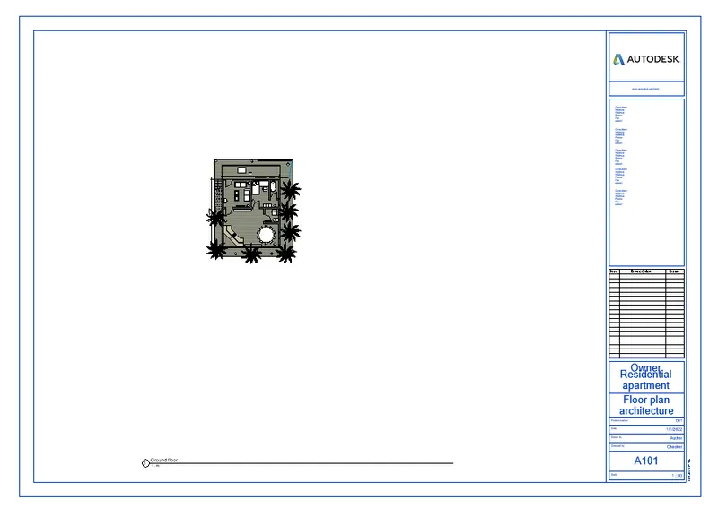
- Floor plan view with annotations -
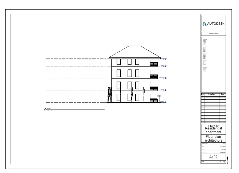
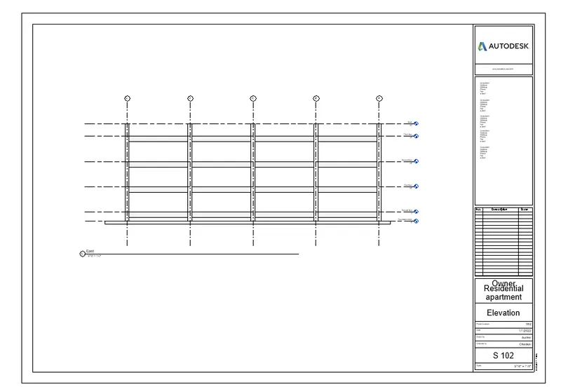
- Elevation -
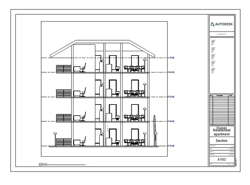
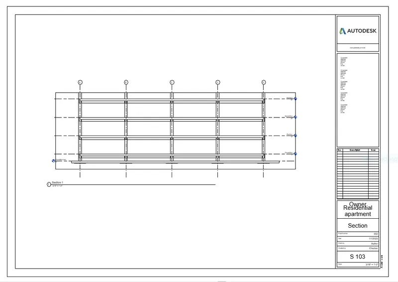
- Section -
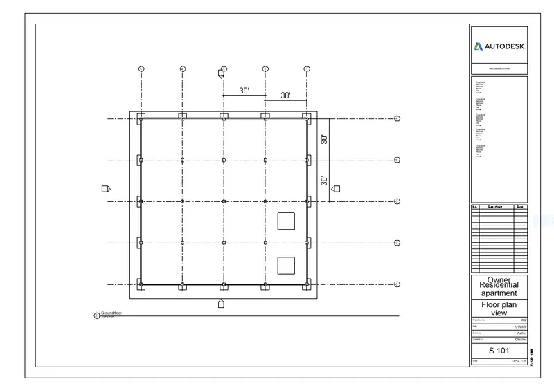
- For structural model add the views to sheet template.
- Floor plan view with annotations -
- Elevation -
- Section -
- Result -
- The given categories are included in sheet template of both architecture and structural template.
- Question no.6
- Ans -
- Aim - To render images of 3D model to include them into sheets.
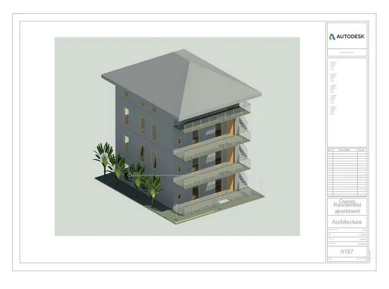
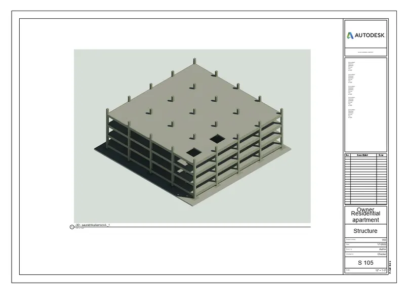
- Introducton - Here we can render the image of 3D model for architectural and structural framing. Render the view to create a photorealistic image of the 3D model. After preparing the 3D view and using the Rendering dialog to select desired settings, click Render to render the image.
- Revit begins the rendering process, rendering the entire image progressively. Revit displays a progress dialog, which shows information about the rendering process. When the rendering process is complete, Revit displays the rendered image in the drawing area. You can then do the following:
- Change render settings, and render the image again.
- Adjust exposure settings, and render the image again.
- Save the rendered image as a project view.
- Export the rendered image to a file.
- Display the building model in the drawing area.
- In the Rendering dialog, click Show the model. To display the rendered image again, click Show the rendering.
- Rendering in Revit can offer a quick turnaround time, quality performance, and user friendliness. It can help drive efficiency and accuracy throughout the design process as updates to floor plans, elevations, and sections can be made as the model.
- Tools used -
- View.
- Render.
- Sheets.
- Process -
- Open the revit file.
- Select the 3D images.
- Go to view tab.
- Click on render command.
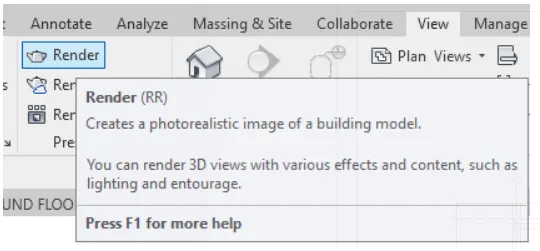
- Select the properties and fix the ligths correctly with proper voltage.
- Adjust the exposure in dialog box.
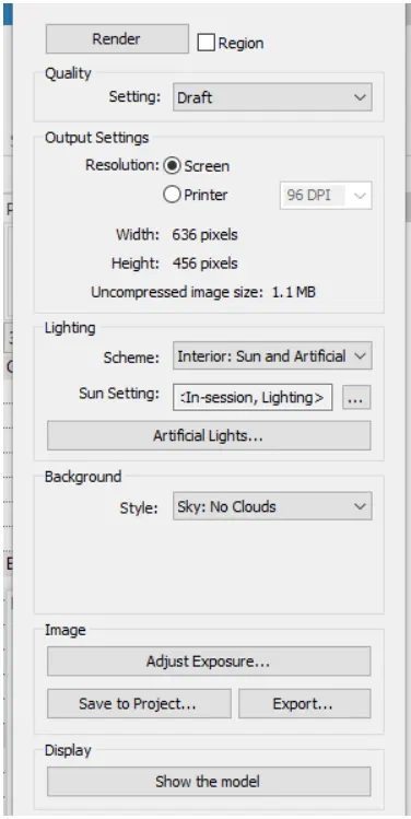
- Click on save to project.
- Open the sheet under view tab.
- Select the type of view to be included.
- These rendering helps us to view in more realistic way.
- Rendering from interior rooms -
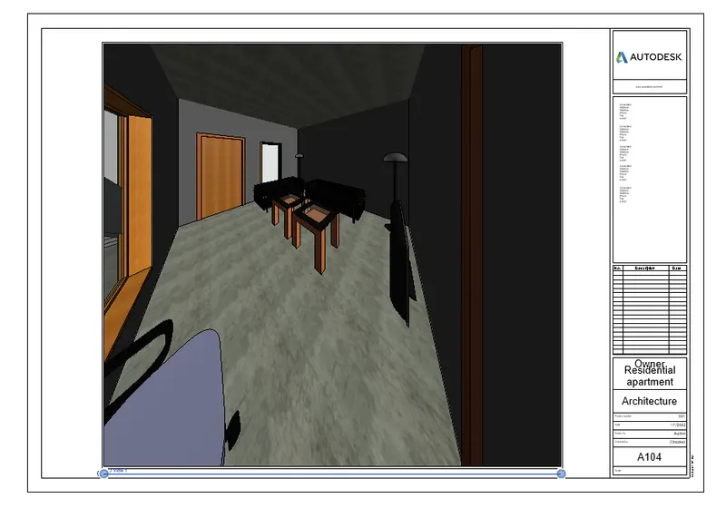
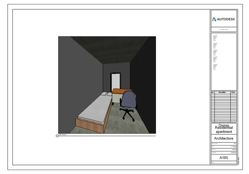
- Rendering from out showing topographic features -
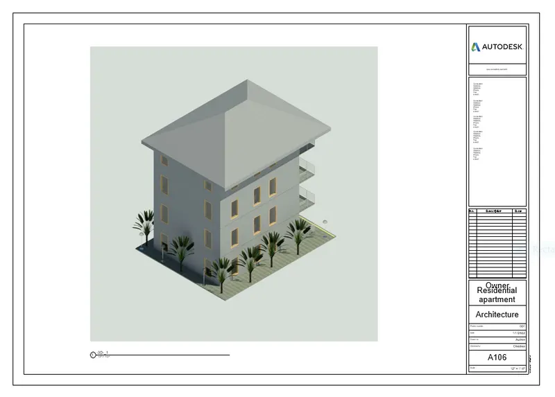
- Rendering through structural framing -
- Question no.7
- Ans -
- Aim - To print the set of drawing sheets created and sumbit the drawing from architectural and structural model.
- Introduction - Here we can print the drawing sheets using print.
- Click File tab
 (Print).
 - In the Print dialog, for Name, select your PDF print driver. If the list does not include a PDF print driver, talk to your system administrator about installing one on your system.
- Click Properties. In the Properties dialog, define settings for the PDF print driver as desired, and click OK.
- To print only the sheet or view in the drawing area:
- Under Print Range, select Current Window to print the entire view or sheet that currently displays in the drawing area, or select Visible Portion of Current Window to print the part of the view or sheet that currently displays in the drawing area.
- Under File, for Name, specify the name and location of the resulting PDF file. If needed, click Browse and navigate to the target folder.
- To print multiple views and sheets:
- Under Print Range, select Selected Views/Sheets.
- Click Select.
- In the View/Sheet Set dialog, select the views and sheets to print to PDF, and click OK.
- Under File, to generate a single PDF file that contains all of the selected views and sheets, select Combine Multiple Selected Views/Sheets into a Single File. To generate one PDF file for each selected view and sheet, select Create Separate Files.
- For Name, specify the name and location of the resulting PDF file. If needed, click Browse and navigate to the target folder. If you are generating multiple PDF files, the specified file name is used as a prefix. It is appended with the names of the selected views and sheets.
- If you are printing multiple pages and you want them to print in reverse order, under Options, select Reverse Print Order.
- To change print settings, under Settings, click Setup.
- When you are ready to print, click OK.
- Tools used -
- File.
- Print.
- Select page.
- Select plotter.
- print.
- Process -
- Select the view.
- Go to file menu and click on print.
- Adjust the settings accordingly to print drawings.
- Result -
- Since there is no printer available, I am unable to print them.
- Drawing sheets are above question in both architectural and structural model.