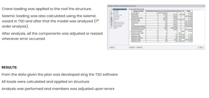
Project 1_Analyze and design a steel building to 10T CRANE as per IS standard code using TEKLA STRUCTURAL DESIGNER.
- Project 1
- Ans -
- Aim -
- Analyze and design a steel building to 10T CRANE as per IS standard code in TEKLA STRUCTURAL DESIGNER.
- Introduction -
- Tekla structural designer is an integrated model based on 3D tool for analysis and design (of both concrete and steel members) in multi material structures. Features include interactive modelling automated structural analysis and design drawing and report creation.
- Tekla structural designer way of working
- Tekla structural designer differes slightly from traditional, modeling analysis and design process.
- Traditional, modeling analysis and design process.
- Summerized below :
- 1. Provide way to input or describe the model
- 2. Analyze the model.
- 3. Design the model.
- 4. Produce calculations.
- 5. Produce drawings.
- Process in Tekla structural designer -
- 1. Input the geometry and loads -
- A key requirement these days is BIM integration or the ability to be able to transfer data from one application to another. Tekla structural designer has tools to automatically import model data from neutral files and from 3D DXF to facilitate BIM integration and we can also build the model directly.
- Once the physical model has been created the next step is loading it. Tekla structural designer allows you to apply a wide range of loads in flexible system of load cases. The system contains among other things a wind load generator available to automatically create wind load cases. You can also generate load combinations automatically.
- We should also consider pattern loading. You can create patterned beam loads automatically and create patterned slab loads manually for design of slabs.
- 2. Analyze and design the model -
- Tekla Structural Designer automatically performs the analyses to enable member desiggn to proceed. This means that analysis and design are combined into a single automated process. The only exception to this rule is slab design.
- 3. Produce reports -
- We can create a wide range of calculations. You can also tailor the calculations extensively to meet your requirements.
- 4. Produce drawings -
- We can produce beam and column detail drawings and member schedules.
- The following analysis type can be run in tekla structural designer -
- 1 st order linear -
- 1 st order linear static analysis is suitable for structures where secondary effects are negligible. Any nonlinear springs or nonlinear elements apresents are constrined to act linearly.
- Load cases and combinations to be considered in the analysis can be pre selected.
- 1 st order non linear -
- This is a nonlinear analysis with loading applied in single step.
- It is suitable for structures where secondary effects are negligible and nonlinear springs/elements are present.
- Load cases and combinations to be considered in the analysis can be pre selected.
- 1 st order modal -
- This is an unstressed modal analysis which can be used to determine the structures natural frequencies.
- The structure is assumed to be in an unstressed state and nonlinear elements are constrined to act linearly.
- 2 nd order linear -
- This is a 2 stage P delta analysis which is suitable for structures where secondary effects are of comparable magnitude to primary effects. Any nonlinear elements presents are constrained to act linearly.
- 2 nd order non-linear -
- This is a nonlinear analysis with loading applied in a single step.
- It is suitable for structures where secondary effects are of comparable magnitude to primary effects and nonlinear springs/elements are present.
- Load cases and combinations to be considered in the analysis can be pre selected.
- 2 nd order buckling -
- This is a linear buckling analysis which can be used to determine a structures susceptibility to buckling.
- The stressed state of the structure is determined from linear analysis therefore nonlinear elements are constrined to act linearly.
- Load cases and combinations to be considered in the analysis can be pre selected.
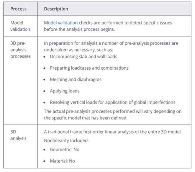
- we will performing 1 st order linear analysis type is run can be summerized :
- Process -
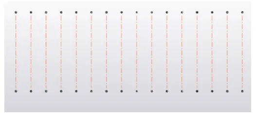
- Initially open the TEKLA structural design software. Now click on new option to create new model workspace. using model ribbon, using the grid line and quick parallel grid line option the vertical grid was drawn.
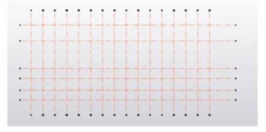
- In the same way vertical grid line drawn.
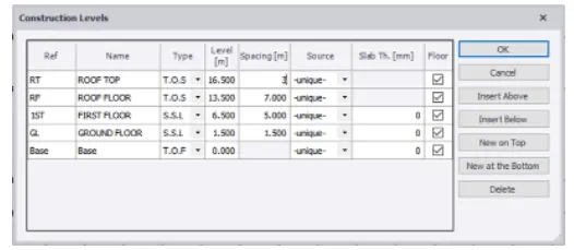
- In the model toolbar select construction levels icon to open the construction levels dialog box.
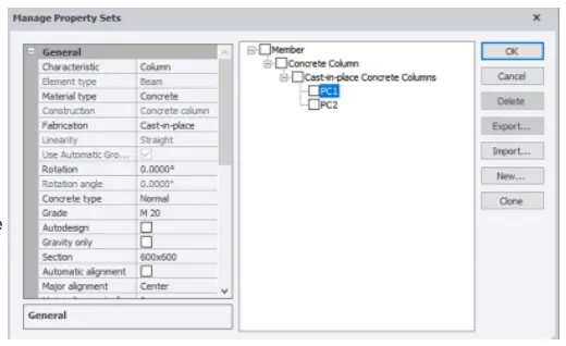
- Now to add pedestal columns in the home menu click on manage property sets options and manage property sets dialog box appears.
- Click on new followed by memebers and select concrete columns.
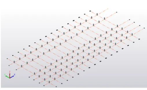
- Now using column option in ribbon tab under the model menu columns was placed at locations as required column was placed at base floor and till ground floor.
- In the similar way concrete column was created steel column renamed as c1. Now using column option in ribbon tab under model menu columns was placed at location as required.
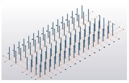
- In the similar way concrete column was created steel beams was created. Now using beam option in the ribbon tab under model menu beams was placed at location
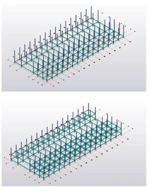
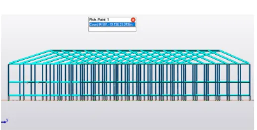
- Rafter beams was designed next for that click on manage property sets dialog box appears. Click on new followed by members and select steel beam. Rename the beam for our own convinience apply properties as required on side. Now the rafter beam were applied using beam option in the ribbon tab under model menu and beams was placed at location as required.
- The rafter beam releases was set to fully fixed at both ends for both rafter beams.
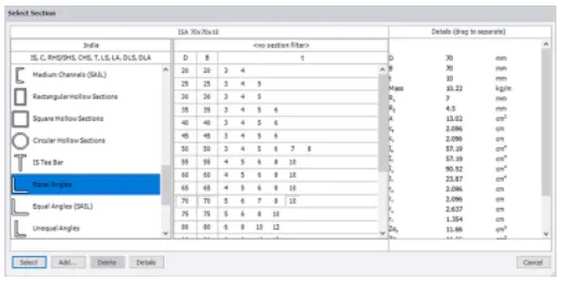
- steel bracing was designed next for that clcik on manage property sets option and the manage property sets dialogue box appears. Click on new followed by memebers and select steel brace. Rename the beam for our own convenience and apply the properties as required on the side. section of size ISA 70 x 70 x 10 was chosen designing the brace.
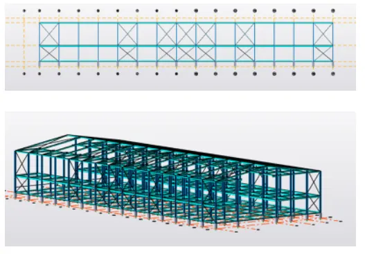
- Now steel braces were applied using the brace option in the ribbon tab under the model menu and braces was placed at locations by selecting 2 opposite corner points. X brace option was selected and drawn. For convienece the braces as drawn on frames on both sides.
-