To Analysis and Design of Steel Structures using TSD
- Que no.1
- Ans -
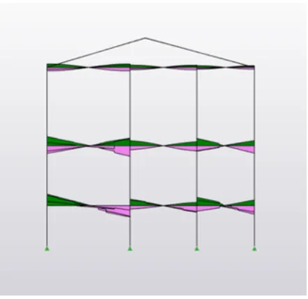
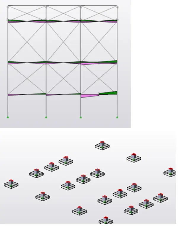
- Aim - To Summarize your study for the bending moment, shear force and deflection diagrams for the elements of the model.
- Tools used -
- File
- Open
- Property Window
- Project Browser
- Result View
- Valiadate
- Settings
- Analyse
- 1 Order linear
- Modification Factor
- Load Combination Box
- Moment Major
- Moment Minor
- Shear Major
- Shear Minor
- Deflection
- Process -
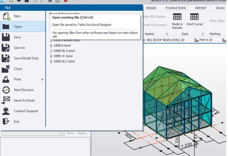
- 1. Let us analyse the structure and check bending moment, shear force and deflection diagrams for element of model for this let us primary open the saved file in the Tekla software using open icon present in the file toolbar.
- 2. Before performing analysis we have to check for same parameters for that let us select the settings icon present in analysis toolbar.
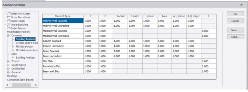
- 3. A dialogbox appears click on first order linear check for number of iterations and tolerance and can modify if required.
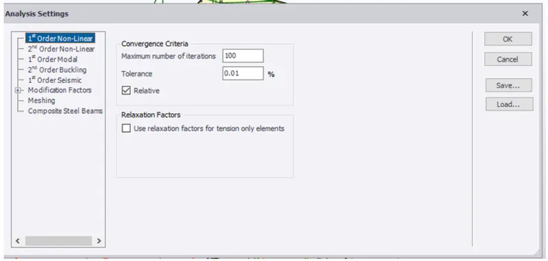
- 4. Then check for modification factor by default these are 1 but if there is any other factor change it to 1 and click ok.
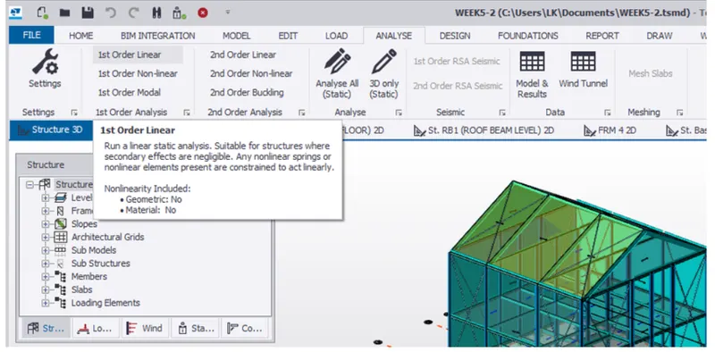
- 5.Once the file is opened for analyzing the model select analysis icon and click on 1 st order linear from options available.
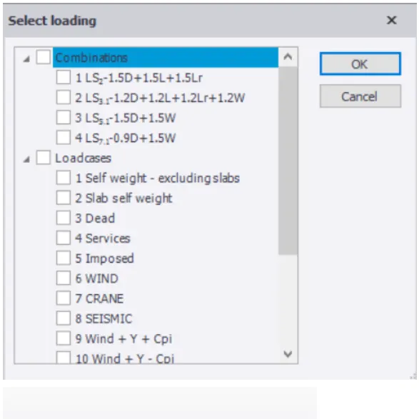
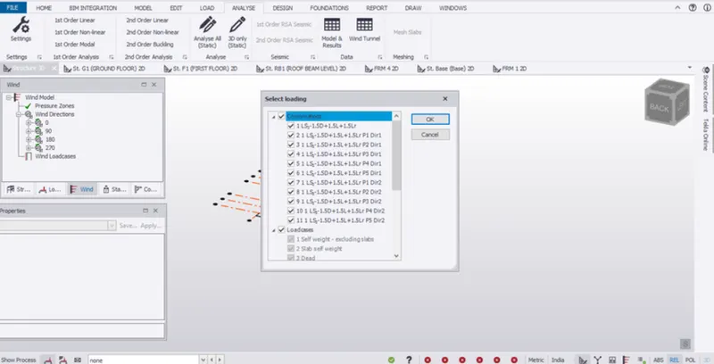
- 6. After clicking on 1 st order linear a dialog box appear where we have to select load cases and load combinations and click ok.
- 7. In this way we have to analyze structure simply for that make use of the result view and we will get any of the required parameters for the analysis that include axial force, shear major, shear minor, torsion, moment major, moment minor can be accessed and also can check their values in different directions (X,Y,Z).
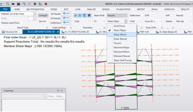
- 8. Now by varying load combinations we can see different values of the parameters and we can modify the properties of the material for worst cases values and modify its properties untill all the load combination are satisfied the value of parameter.
- 9. Now let us check whether our analysis is right for this let us finish the above mentioned steps now and check whether our mdel satisfies load combinations so once above steps done select solver option shown in the status menu of the project browser.
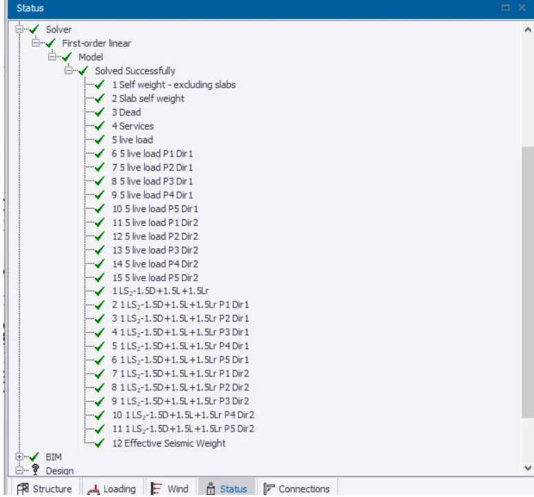
- From here we can see that the model satisfies all load combinations now let us sumerise it.
- Bending moment -
- Bending moment can be defined as bending of the members due to action of forces.
- It is one of the most important parameter to be considered in the region. by analyzing we could know bending moment values for different load cases and is generally calculated by considering moment along all sides of members to calculate bending moment the magnitude of force is multiplied by distance of support from point of support. A beam may fail due to shear force before failure in bending.
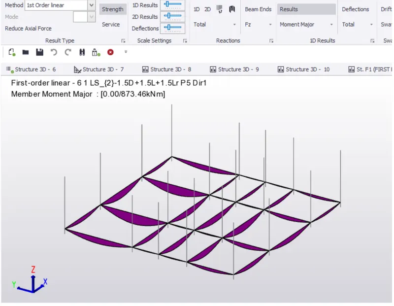
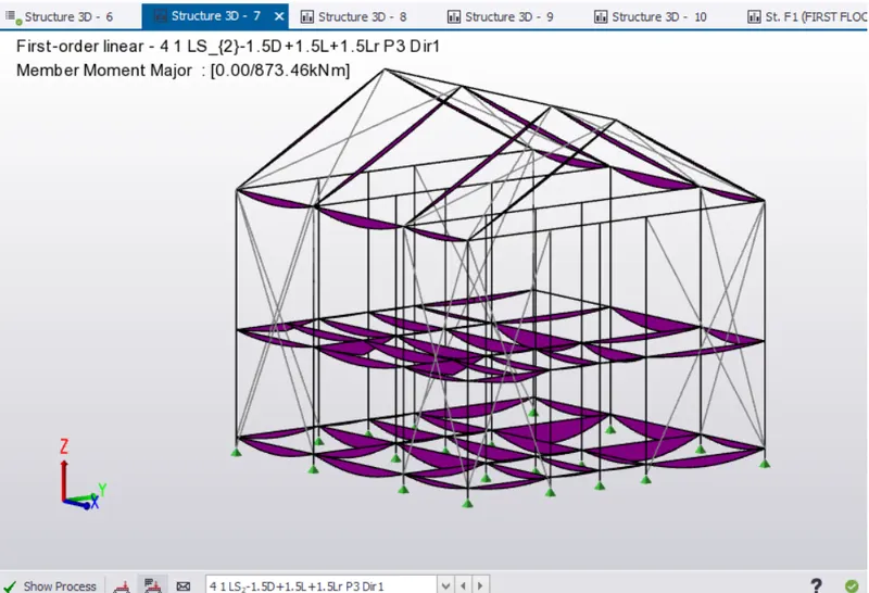
- For finding the bending moment of structure in tekla software we must click on the result view of the created structure then select moment minor/major option from the available option and we can observe bending moment by varying load combinations.
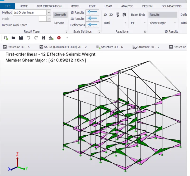
- Shear force -
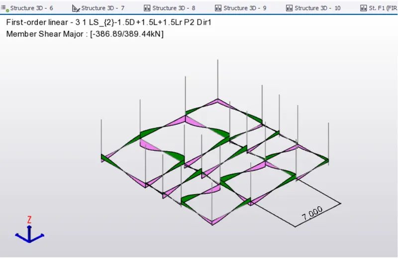
- Shear force is defined as force thet acts in a direction parallel to cross section of body or simply we can say shear force is unbalanced vertical force that is acting on the right or left of the section. The shear force at a section is an algebric sum of the lateral forces acting on all the sides of section.
- Deflection diagrams -
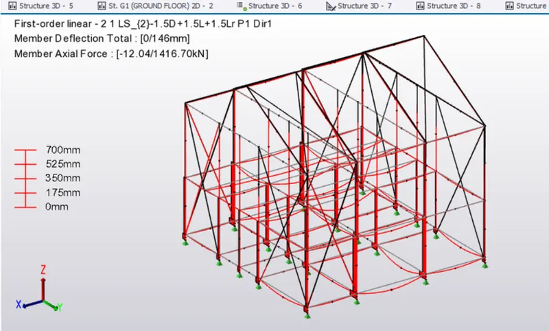
- Deflection diagram can be simply explained that whenever load acts on the member of deviate from its original position might may be small that deviation called deflection.
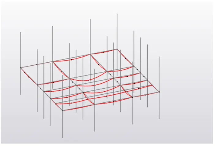
- Deflection to a certain extent is ok because when load is removed it comes back to its original position but when there is more deflection there is possibility of failure member. for finding bending and shear force of the structure in tekla software we we must click on result view of created structure then select the deflection icon available and we see different deflection diagrams for the structure.
- Result -
- Summrise study for bending moment, shear force, and deflection diagrams for elements of the model and also have displayed these parameters in our model for various load combinations.
- Que no.2
- Ans -
- Aim -
- Based on the analysis design the members and outline the thought process in selecting the member sizes along with the foundation design
- Tools used -
- File
- Open
- Property Window
- Project Browser
- Result View
- Valiadate
- Settings
- Analyse
- 1 Order linear
- Modification Factor
- Load combination box
- Foundation
- Pile base foundation
- Design member option
- Copy
- Edit
- Save as
- Review View
- Result View
- Process -
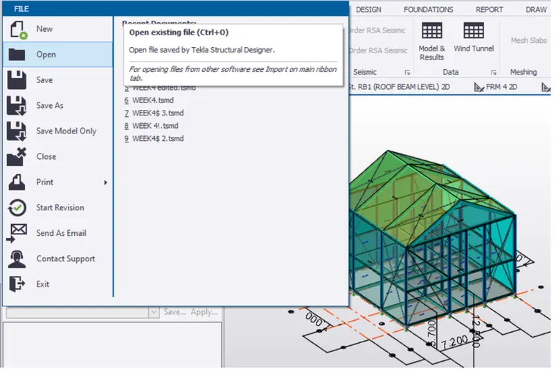
- 1.Open the tekla software using the open icon present in file toolbar.
- 2.Before peforming check parameters for that let us select setting icon present in analysis toolbar.
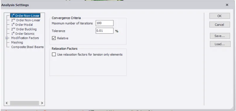
- 3. a dialog box appears click on 1 linear option and check for numbers of iterations and tolerance and can if modify is required.
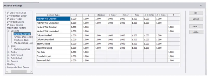
- 4. Check for modification factor by default these are 1 but if there is any other factor change to it to 1 and click ok.
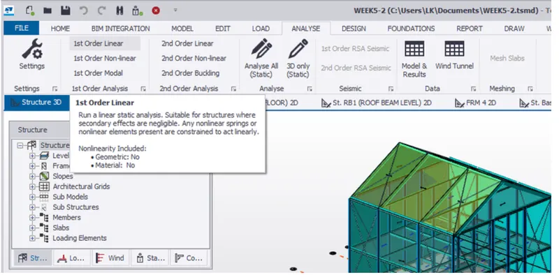
- 5. Once the file is opened for analyzing the model select analyse icon and clicko on first order linear from the options available.
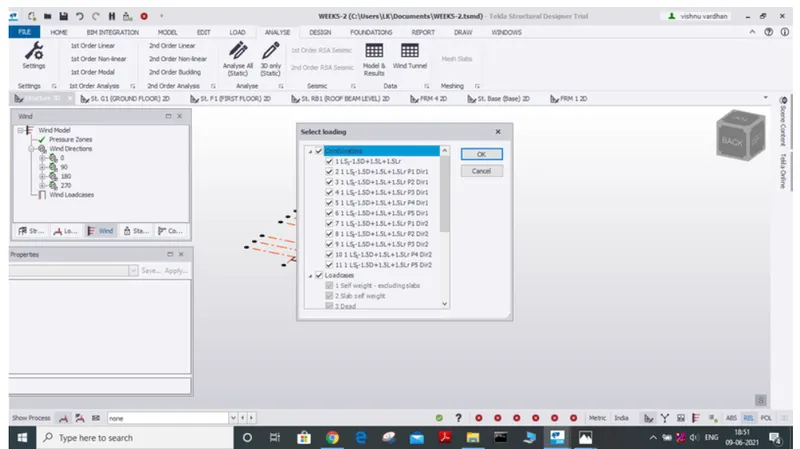
- 6. After clicking on 1 st order linear a dialog box appears where we have to select load cases and load combinations and click ok.
- 7. In this way we can analyze a structure simply for that make use of result view we will get any required parameters for analysis that include axial force, shear major, shear minor, torsion, moment minor, moment major can be accessed and check their values at different directions (X,Y,Z).
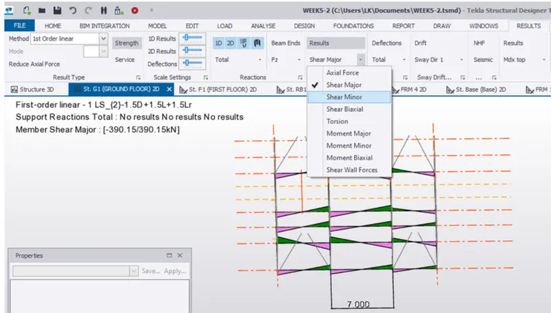
- 8. Now by varying load combinations we can see different values of parameters and we can modify properties of the material for worst case values and modify its properties untill all load combinations will have satisfied the value of parameter.
- 9. Now let us check whether our analysis is right for this let us finished above mentioned steps now ans check whether our model satis fies load combinations so, once the above steps are done select the solver option shown in the status menu of the project browser.
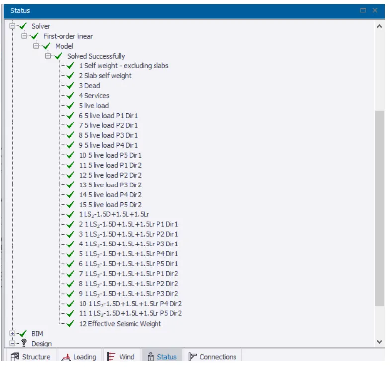
- 10. Analysis of model is done and let us suppose beam for that select beam which you are designing then right click on select beam based on the analysis.
- 11. Large number of options will appear there we can select design /check member after selecting design member two options will appear select static.
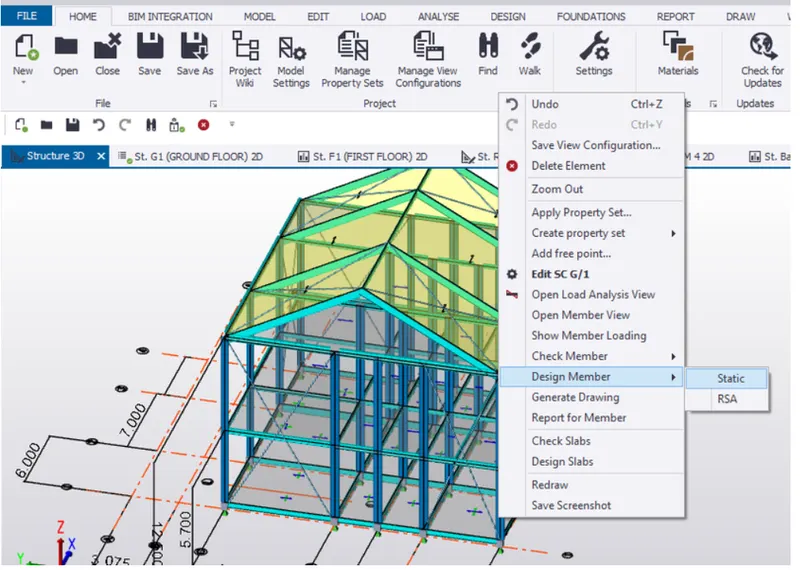
- 12. A new table appear starting whether memebr satisfies the load combinations, forces, bending moment axial force etc.