Week 11 Challenge
- Question no 1.
- Ans -
- Files are attached below.
- Aim - To calculate friction load and friction force.
- Introduction - Here we can find the friction load and force of LNG pipe rack. We find friction force if TEFLON pad is used between shoe and pipe support.
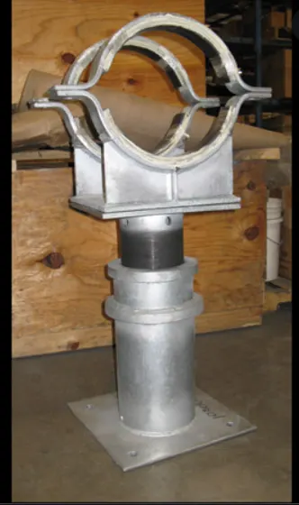 pipe shoe image.
- Pipe rack structure - Pipe racks are used in petrochemical, chemical and power plants. They are designed to support pipes, instrument cables and power cable tray.
- Teflon - Teflon is used to coat a variety of products because it's waterproof, cuts down on friction, and creates a nonstick surface. Teflon reduce friction between two surfaces of materials.
- Friction load - Friction is proportional to the load or weight that presses the surfaces together. Thus, the ratio of friction F to load L is constant. This constant ratio is called the coefficiant of frictionand is usually symbolized by the Greek letter mu (μ). Mathematically, μ = F/L. Because both friction and load are measured in units of force. Friction load is a load which take in to account when friction is occured on structure.
- Friction force - Frictional force refers to the force generated by two surfaces that contacts and slide against each other. there are different types of frictional forces. The friction that takes place between solid surfaces is classified as Static, Kinetic, Rolling, and Sliding Friction. The friction that takes place between fluids and gases are termed as fluid friction. The general formula for frictional force is given by F = μN.
- Given - Vertical force = 125 KN.
- TEFLON pad is used between shoe and pipe support.
- Process -
- Friction force = pipe gravity load x friction coefficiant.
- Friction force = 125 x 0.15.
- Stainless friction coefficiant = 0.15.
- Friction force = 18.75 KN.
- Friction force is temporarily acting friction load.
- So friction load = 18.75 KN.
- Friction coefficiant for teflon = 0.1.
- Friction force due to teflon = 125 x 0.1 = 12.5 KN.
- Friction force due to teflon = 12.5 KN.
- Question no 2.
- Ans -
- Files are attached below.
- Aim - To find out types of support of given images.
- Introduction - Here we can find the type of support of images with respect to support condition. The given is pipe rack structure in images. We can find the support type as fixed or pinned base.
- Fixed support - A fixed support is the most rigid type of support or connection. It constrains the member in all translations and rotations (i.e. it cannot move or rotate in any direction). The easiest example of a fixed support would be a pole or column in concrete.
- Pinned support - A pinned support can resist both vertical and horizontal forces but not a moment. They will allow the structural member to rotate, but not to translate in any direction.
- Strut - a structural piece designed to resist pressure in the direction of its length.
- Spring strut - The strut attached spring at support for stiffness and suspension purpose.
- Guyed strut - a guy, is a tensioned cable designed to add stability to a free-standing structure. Guyed strut is strut for attched guyed cable for support.
- Stop or Semi Anchor (Guyed + Rest + Stop ) or Rigid Strut - A rigid Strut is a dynamic restraint that is used specifically to reduce dynamic loads. They act as compression as well as tension element. Struts can also be a good alternative to the normal piping guide supports.
- Given - Attached given figures.
- Process -
- Figure 1 -
- Fixed support beacuse both ends are jointed or fixed to members.
- Figure 2 -
- Pinned support.
- Figure 3 -
- Fixed support.
- Figure 4 -
- Fixed and pinned both.
- Figure 5 -
- Pinned support.
- Figure 6 -
- Pinned support because both jointed by pin support.
- Question no 3.
- Ans -
- Files are attached below.
- Aim - To design pipe rack bent in oil plant.
- Introduction - Here we given that the typical pipe rack configuration and its plan layout. For design of pipe rack structure use given data.
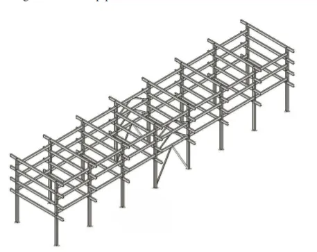
- Pipe rack structure - Pipe racks are used in petrochemical, chemical and power plants. They are designed to support pipes, instrument cables and power cable tray. A Pipe rack is a structure designed and installed specifically to support multiple pipes, where an adequate building or structure is not available (mainly outside the building). Pipe racks are necessary for arranging the process and utility pipelines throughout the plant. It connects all the equipment (installed at a different location) with lines that can not run through adjacent areas.
- They are also used to support mechanical equipment, vessel and valve access platforms.
- Pipe rack transfter fluid between equipment and storage areas.
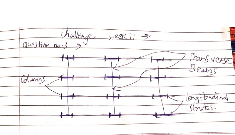
- Transverse frames are moment resisting frames.
- They support gravity loads and resist lateral load in transverse direction.
- Transverse frames are connected with longitudinal struts.
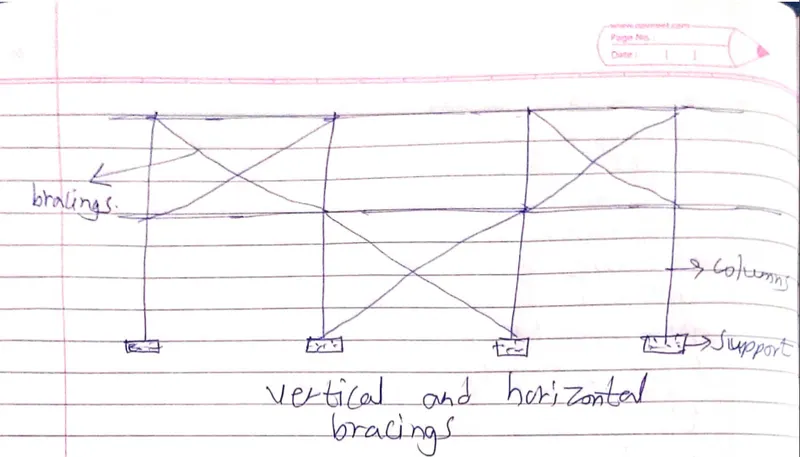
- Components of pipe racks -
- Transverse beams.
- Columns.
- Longitudinal struts.
- Vertical and horizontal bracings.
- Types of pipe rack -
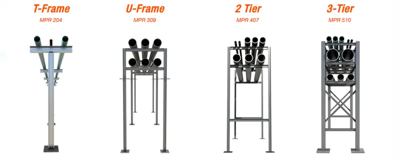
- Based on transverse frame -
- T frame.
- U frame.
- Based on number of tier -
- 2 tier pipe rack.
- 3 tier pipe rack.
- Based on longitudinal frame -
- Strutted main pipe racks.
- Unstrutted secondary pipe racks.
- Loading on pipe racks -
- Dead load.
- Structure dead load (Ds)
- Operating dead load (Do).
- Empty dead load (De).
- Test dead load (Dt).
- Thermal load.
- Thermal friction force (Ff).
- Thermal anchor force (Af).
- Given -
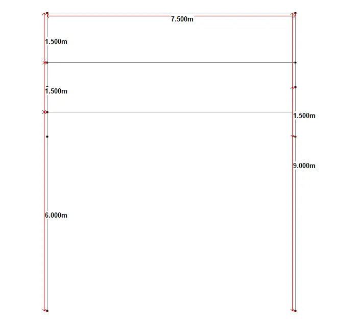
- Spacing between two column i.e. width = 7.5 m.
- Total height = 9.0 m.
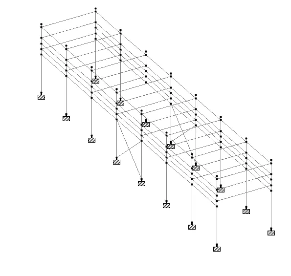
- 7 spans at 6.0 m.
- Cable tray = 150 mm.
- Pipe diameter = 24, 12, 18, 8 inches.
- 2 tier spacing = 1.5 m.
- Center to center distance between column = 0.75 m.
- Process -
- Open staad -> create new model -> Define nodes and beams as per given data.
-
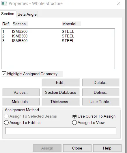
- Properties -> add section -> assign property.
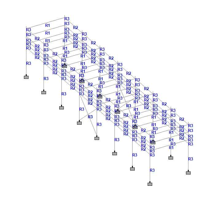
- Support -> create support - > assign support.
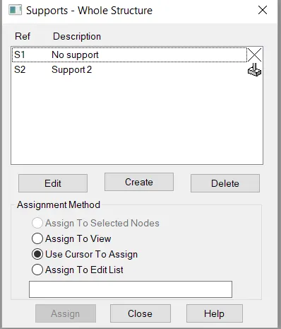
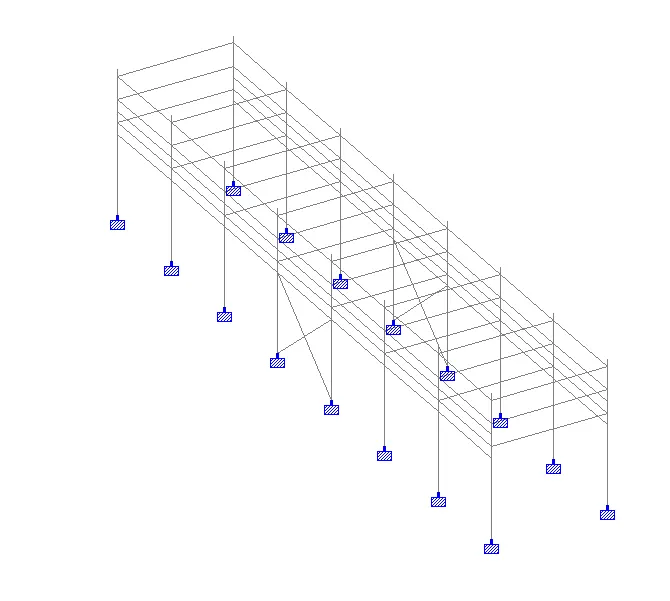
- Loading - > add load defination -> add load case details -> assign loads to members.
- Uniform operating dead load = 1.9 KN/m^2.
- Pipe load = 1.9 x 7.5 = 14.28 KN/m.
- 60% of it = 14.28 x 0.6 = 8.5 KN/m.
- Point load = 15 KN.
- 60% of it = 9 KN.
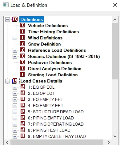
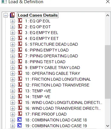
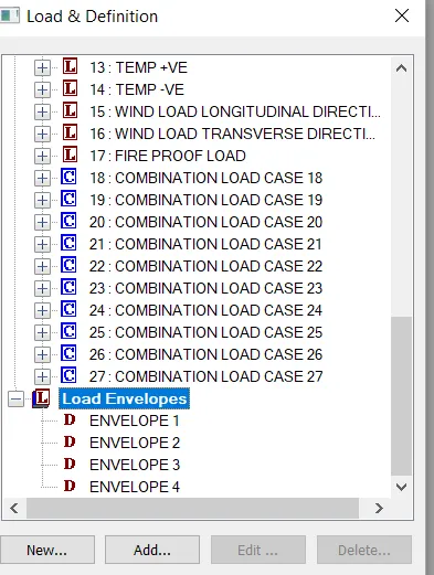
- Load combination -> add ->envelope -> add combinations and loads.
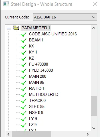
- Design parameters -> add parameters.
- Run analysis -> check results.