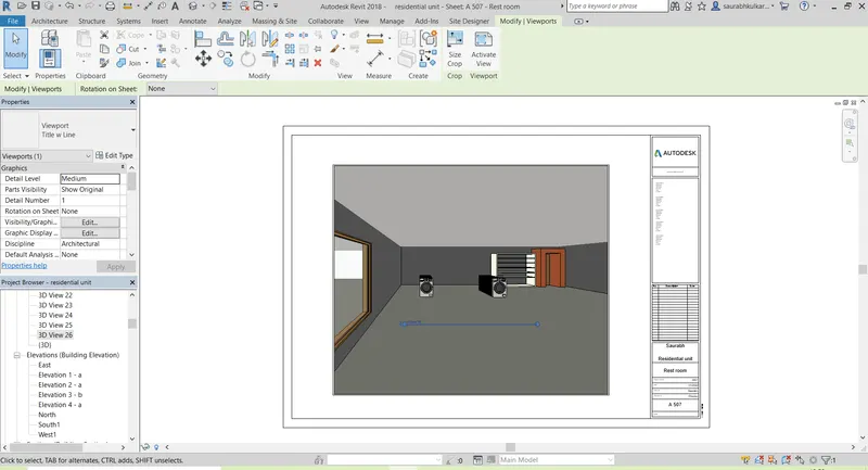
3D Creation of Celing, Roof, Architectural plan, Structural plan, Sectional view, Elevation view and Camera specific view for a house plan using REVIT
- Question no.1.
- Ans -
- Aim - To model the ceiling from the architecture tab above walls.
- Introduction - Here we model the ceiling of week 3 project. Tools which is used as architecture tab, ceiling, sketch ceiling, pick lines.
- A ceiling is an overhead interior surface that covers the upper limits of a room. It is not generally considered a structural element, but a finished surface concealing the underside of the roof structure or the floor of a story above. Ceilings can be decorated to taste, and there are many fine examples on ceilings especially in religious buildings.
- Types of ceiling -
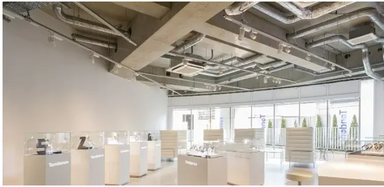
- Exposed Ceilings - this kind of ceiling arrangement would completely expose the structural and mechanical component of building thus omitting a concept of finished ceiling. This arrangement lacks a discomfort in aesthetics but gains many advantages like the economy.
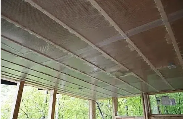
- Tightly attached ceiling -
- Interstitial ceilings - An interstitial space is defined as an intermediate space kept between regular-use floors. It is commonly located in hospitals and laboratory-type buildings to allow space for the mechanical systems of the building. Laboratory and hospital rooms are easily rearranged throughout their lifecycles and therefore reduce lifecycle cost.
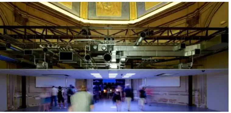
- Acoustical Ceilings - This ceiling is mainly implemented to control sound reverberation in a hall where there is the possibility of large sound propagation to make the hearing comfort zone. The acoustic ceiling material is made from fibrous materials that would absorb sound energy unlike other materials like plaster or gypsum ceilings. These materials do not reduce transmission of sound between the spaces. They result in a reduction in the amount of sound that reflects into space. Hence it can be used to bring the modify acoustic character of space.
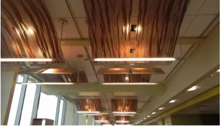
- Radiant Chilled Ceilings - Radiant chilled ceilings include a network of chilled water coils in ceiling panels with insulation above. For some systems, pipework may be incorporated into plaster board. But this is found less efficient as plaster is an insulator. The ceiling surface then cools the occupied space by both radiation and convection, providing temperatures throughout the space and avoids draught. The space requirement for chilled ceilings is found to be less, which may be installed with a depth of just 100mm. For some, a small-bore cooling coils can be embedded in plaster ceiling.
- Convective Chilled Ceilings - These types of ceilings are a deviation from radiant chilled ceilings, in which the network of chilled water pipes incorporates fins, increasing the proportion of cooling that is provided by convection.
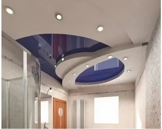
- Suspended Ceilings - These are secondary ceilings suspended from the structure above (typically a floor or roof slab), creating a void between the underside of the slab and the top of the suspended ceiling. This void can provide a useful space for the sprinklers, distribution of heating, ventilation, and air conditioning (HVAC) services and plumbing and wiring services. This also provides a display place for the installation of speakers, and smoke detectors, motion detectors, light fittings, wireless, antenna, CCTV, fire and so on. It provides an air ‘plenum’, in which the void itself forms a pressurized ‘duct’ to supply air to or extract it from the taken space below.
- Process -
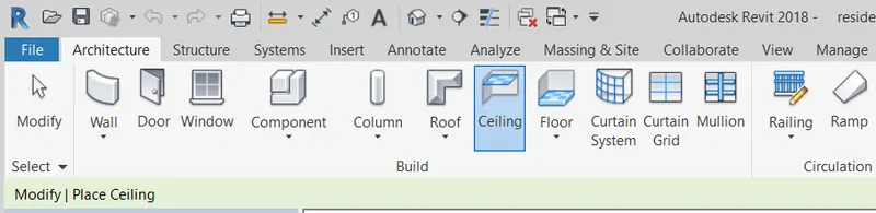
- Click on ceiling tool on architecture menu.

- Click on sketch ceiling and boundary by using pick lines option and click on finish edit option.

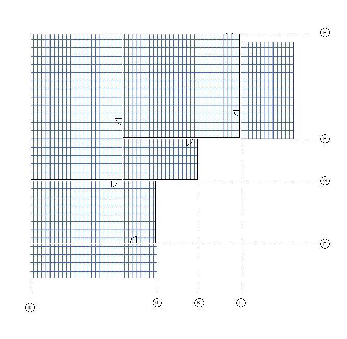
- Set the level upto which we need ceiling ground floor in this case.
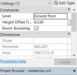
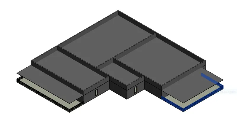
- Ceiling has been added successfully.
- Question no.2.
- Ans -
- Aim - To model the roof above ceilings with footprints of the ceiling.
- Introduction - To use toolbar as architecture tab, roof, pick line, property browser.
- Roof - A roof is the top covering of a building, including all materials and constructions necessary to support it on the walls of the building or on uprights, providing protection against rain, snow, sunlight, extremes of temperature, and wind. A roof is part of the building envelope. The characteristics of a roof are dependent upon the purpose of the building that it covers, the available roofing materials and the local traditions of construction and wider concepts of architecture design and practice and may also be governed by local or national legislation. In most countries a roof protects primarily against rain. A verandah may be roofed with material that protects against sunlight but admits the other elements. The roof of a garden conservetary protects plants from cold, wind, and rain, but admits light.
- Process -
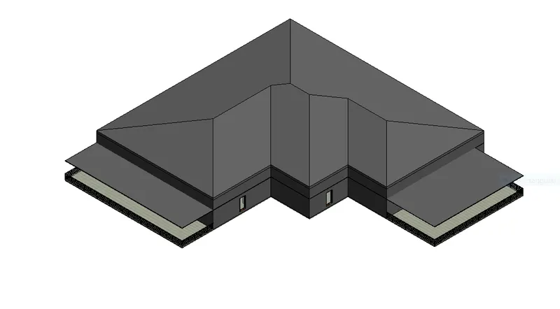
- From architecture tab select roof.
- After select pick lines in modify.
- Add or adjust roof slope as 10 degree on roof toolbars .
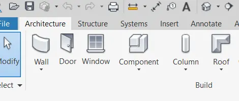

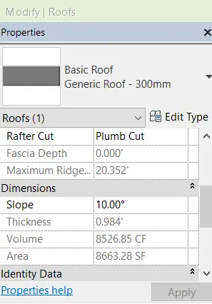
- Select desire lines upon which roof is required.
- Question no.3.
- Ans -
- Aim - To create plan views for ground and first floor level and seperate them into architecture and structure plans.
- Introduction -
- Architecture plans - In architecture and building engineering, a architecture plan is a drawing to scale, showing a view from above, of the relationships between rooms, spaces, traffic patterns, and other physical features at one level of a structure. Dimensions are usually drawn between the walls to specify room sizes and wall lengths. Floor plans may also include details of fixtures like sinks, water heaters, furnaces, etc. Floor plans may include notes for construction to specify finishes, construction methods, or symbols for electrical items.
- Structure plans - A structure plan is a framework to guide the development or redevelopment of an area by defining the future development and land use patterns, areas of open space, the layout and nature of infrastructure (including transportation links), and other key features and constraints that influence how the effects of development are to be managed.
- Structure plans comprise one or more maps, plans or diagrammatic representations of the proposed layout, features, character and links for areas being developed or redeveloped. The maps or plans in structure plans do not typically go into such detail as to define individual lot boundaries or the physical form of buildings and structures. The maps, plans or representations are usually supported by text explaining the background to the issues that initiated the structure plan and the approaches to manage those issues.
- Process -
- a. Architecture plan must have walls, floors, and all the components placed within the building.
- View tab and plan views this toolbars are used.
- Open the revit file.
- Go to plan views in view tab.
- Select level for which we want plan and click on it.
- Click apply same for ground, first and roof.
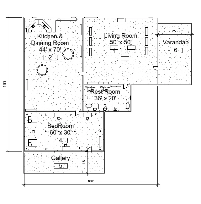
- Ground floor -
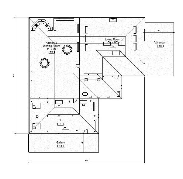
- First floor -
- b. Structure plan must have details of only walls, floors, and columns.
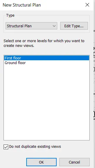
- Tools required are view tab and structural view.
- open the revit file.
- Go to structural views in view tab.
- Select the level for which we want plan and click on it.
- Click apply same for ground, first, roof.
- Ground floor structure plan -
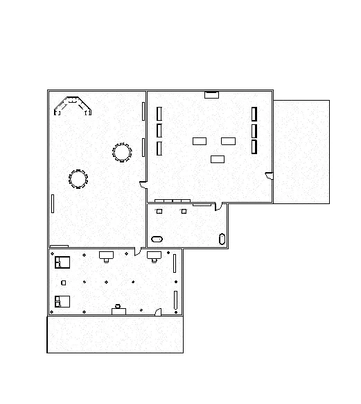
- First floor structure plan -
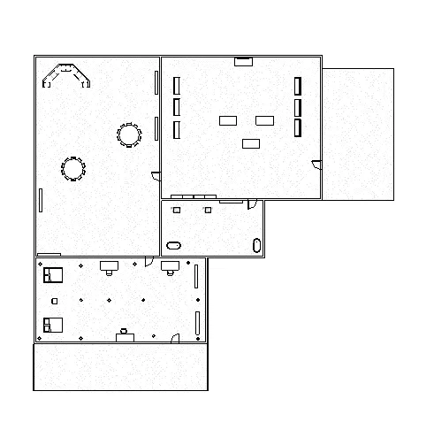
- Question no.4.
- Aim - Add dimensions to walls and floors with reference to longitudinal and transverse grids created project file.
- Introduction - Here the tools used are architecture, grids, annotate, aligned.
- Architecture plans - In architecture and building engineering, a architecture plan is a drawing to scale, showing a view from above, of the relationships between rooms, spaces, traffic patterns, and other physical features at one level of a structure. Dimensions are usually drawn between the walls to specify room sizes and wall lengths. Floor plans may also include details of fixtures like sinks, water heaters, furnaces, etc. Floor plans may include notes for construction to specify finishes, construction methods, or symbols for electrical items.
- Structure plans - A structure plan is a framework to guide the development or redevelopment of an area by defining the future development and land use patterns, areas of open space, the layout and nature of infrastructure (including transportation links), and other key features and constraints that influence how the effects of development are to be managed.
- Annotate - Here we can use for measure dimensions of walls, floors etc. There are many option to annotate such as linear, aligned, circular etc.
- Grids - Here we Revit automatically numbers each grid. To change the grid number, click the number, enter the new value, and press enter. You can use letters for grid line values. If you change the first grid number to a letter, all subsequent grid lines update appropriately. As you draw grid lines, the heads and tails of the lines can align to one another. If grid lines are aligned and you select a line, a lock appears to indicate the alignment. If you move the grid extents, all aligned grid lines move with it.
- Grids are give the numbering to the walls or floors on exterior panels. Grids gives numbering in longitudinal and transverse direction.
- Process -
- In the architectural tab click on grid tool and start drawing grids from left to right and top to bottom.


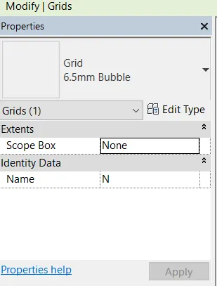

- After drawing the grids, go to annotate and choose align option and annotate the distanced between vertical and horizontal grids and also components in plan.
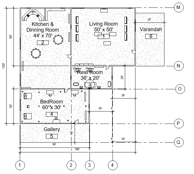
- In structural plan view, add grids and annotate the distances between the grid lines.
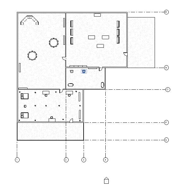
- Architectural plan view -
- Structural plan view -
- Question no.5
- Aim - To create a sheet template from view tab and adjust the parameters on the sheet to add appropriate views.
- Introduction - Here we can use the sheet for locate the plan view in particular sheet to present in front of client.
- Sheet gives the border to plan view with name template and other information on it. the tools used are view, sheet, project browser. Create views on a project template before you start building the model to streamline the project documentation process.
- When creating a project template, you can include sheets in the template. Start with a blank project file, and create the standard views and levels that each project should include. Leave the views empty, but assign standard names to them. To create a standard set of construction documents, create sheets using the desired title blocks. Add views to the sheets, using the desired viewport templates and view title types. Then save the empty project as a project template.
- When you create a project using this project template, all of the views and sheets are already created and listed in the Project Browser. As you start to draw the building model in the project views, the views on the sheets update automatically. This technique streamlines the project documentation process and maintains organizational standards.
- Process -
- In the view tab click on sheets and click on A1 metric and click ok.
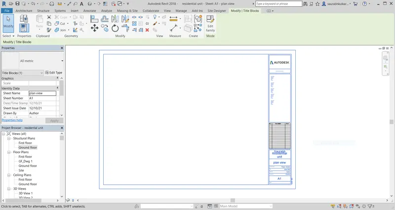
- Then make required changes to detail sheet by double clicking or using project browser.
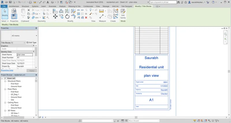
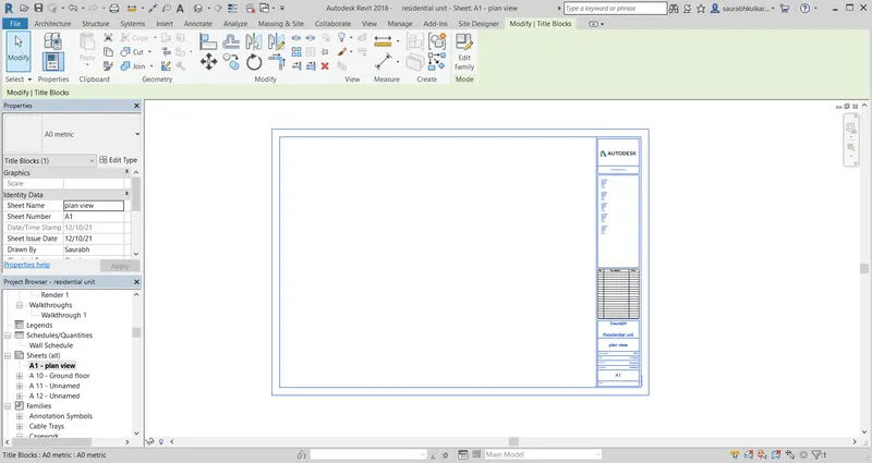
- The required sheet with parameters is obtained.
- Question no.6
- Aim - To use the elevation tab, create elevation views looking at your building from East, North, South, and West.
- Introduction - The tools used are view, elevation, project browser. Here we create the elevation from east,north,south,west sides. Elevation is a looks it from outside of the model. Elevation is frontal views or sided views are taken place. Elevation views are part of the default template in Revit Architecture. When you create a project with the default template, 4 elevation views are included: north, south, east, and west. It is in elevation views where you sketch level lines. For each level line that you sketch, a corresponding plan view is created.
- You can create additional exterior elevation views and interior elevation views. Interior elevation views depict detailed views of interior walls and show how the features of the wall should be built. Examples of rooms that might be shown in an interior elevation are kitchens and bathrooms.
- Process -
- In the view tab click on elevation tool.
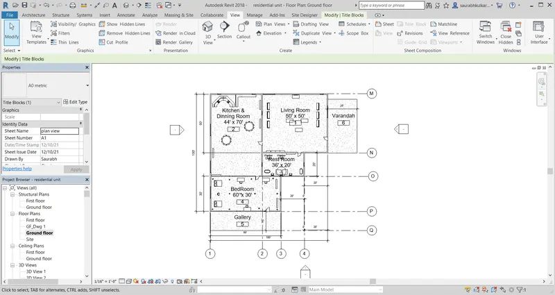
- On the 4 sides of drawing, add the elevation logo that appears.
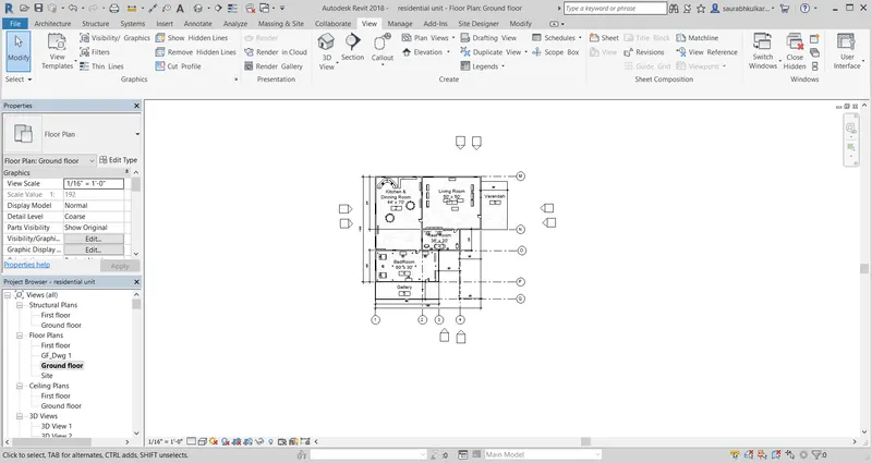
- In the project browser there will be 4 views named north, west, east and south. Double click on the required view to open it.
- East elevation view -
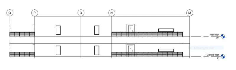
- North elevation view -
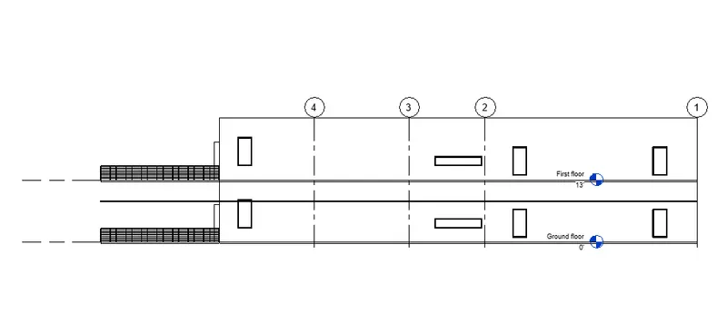
- South elevation view -
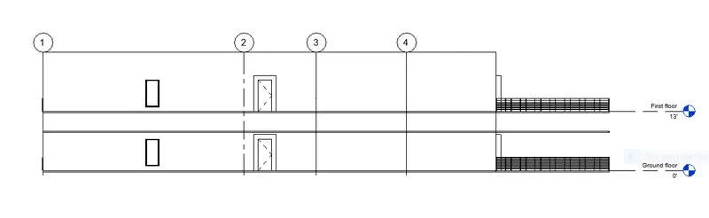
- West elevation view -
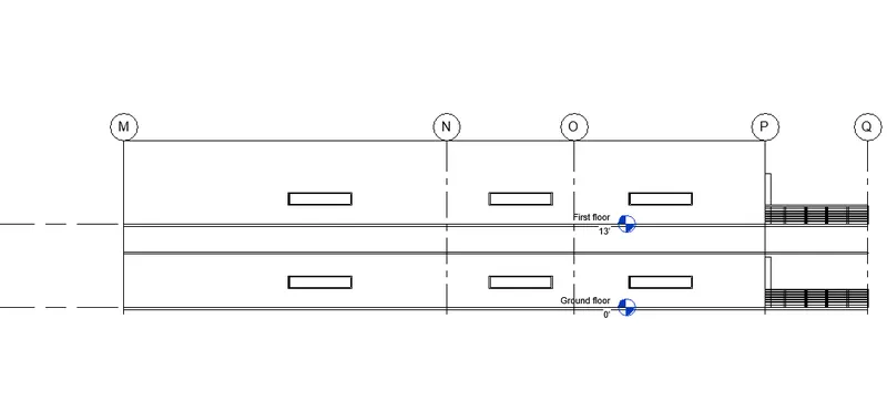
- Question no.7
- Aim - To produce section cut through each room either cutting across longitudinally or in transverse direction.
- Introduction - The tool used as view, section, property browser. The section cut is cutting plan view in one direction. Add a section line and crop region to define a new section view. Open a plan, section, elevation, or detail view. Click View tab Create panel section. In the Type Selector, select a view type from the list, or click Edit Type to modify an existing view type or create a new view type.
- Open a plan, section, elevation, or detail view.
- Click View tabCreate panel
 (Section).
 - (Optional) In the Type Selector, select a view type from the list, or click Edit Type to modify an existing view type or create a new view type.
- Place the cursor at the starting point of the section, and drag through the model or family.
Note: You can snap a section line parallel or perpendicular to a non-orthogonal datum or wall. Snapping to a wall is available in plan views.
- Click when you reach the end point of the section. The section line and the crop region appear and are selected.
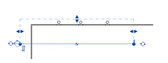
- If desired, resize the crop region by dragging the blue controls. The depth of the section view changes accordingly.
- Click Modify or press Esc to exit the Section tool.
- To open the section view, double-click the section header, or select the section view from the Sections grouping of the Project Browser. The section view changes when the design changes or the section line is moved.
- Process -
- In the view menu click on section tool.

- Draw the sectional line to get the view wherever sectional view is required.
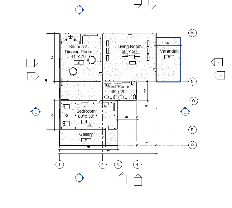
- In project browser we find sectional views double click on required sectional view to open it.
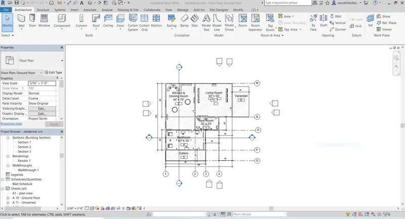
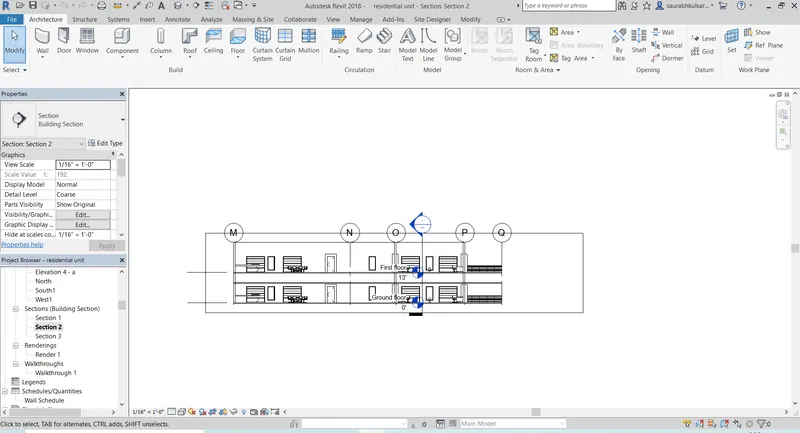
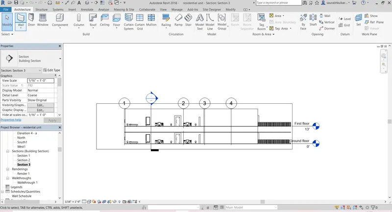
- The required sectional views longitudinal and transverse are obtained.
- Longitudinal views -
- Transverse views -
- Question no.8
- Aim - To classify all the views using design or documentation category using Properties browser.
- Introduction - Here we define the plan,elevation and section views. We can introduce the a plan view is a orthographic projection of a 3-dimensional object from the position of a horizontal plane through the object. In other words, a plan is a section viewed from the top. In such views, the portion of the object above the plane is omitted to reveal what lies beyond. In the case of a floor plan, the roof and upper part of the walls may be left out. Basically, a plan view is just another name for the top view of a 3D object.
- Plan view mostly referred to Civil Engineering Drawing and it is Top view and if its external appearance.Some drawings mention the sectional detail viewing from top at different levels such as Ground plan, First floor plan, Second floor plan and so on.
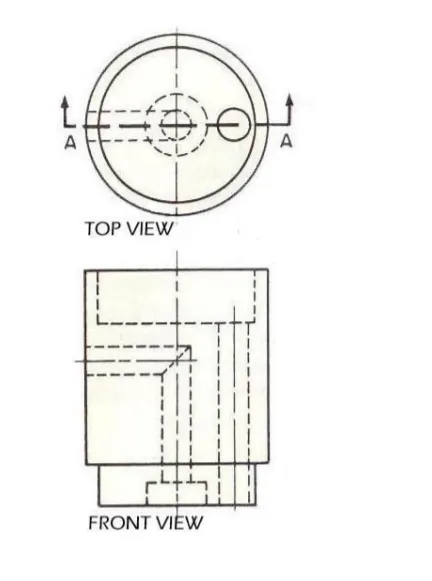
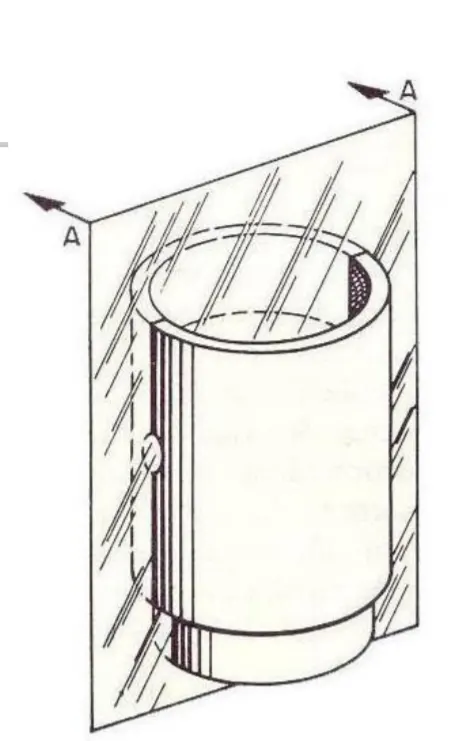
- Section view - A section view is a view used on a drawing to show an area or hidden part of an object by cutting away or removing some of that object. The cut line is called a “cutting plane”, and can be done in several ways. The following slides will help show the several methods or types of “section views”.
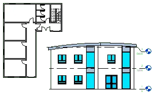
- Elevation view - An elevation is a view of a building seen from one side, a flat representation of one face. This is the most common view used to describe the external appearance of a building. Each elevation is labelled in relation to the compass direction it faces, e.g. looking toward the north you would be seeing the southern elevation of the building. Buildings are rarely a simple rectangular shape in plan, so a typical elevation may show all the parts of the building that are seen from a particular direction.
-
View your model from numerous elevation perspectives.
-
View tab ->Create panel ->Elevation drop-down ->Elevation.
-
- Process -
- View - It is nothing but the way we seen an object in different direction.
- Plan view - The plan view is nothing but looking at a object from the top and this view helps us to draw or plan the room inside building.
- Sectional view - It is the view we get when a building or an object is cut along a line and viewd from one of the sides. This helps us to understand how it looks when it is cut from there.
- Elevation view - It is the view obtained when we look at something from side, it show how tall the object is and how it looks from sides.
- In property browser of revit software we have all these views using which we can clearly design and document a properly and clearly.
- Question no.9
- Aim - To create multiple sheets using sheet template.
- Introduction - Tools used are view, sheet, properties, graphics, insert, image.
- Create views on a project template before you start building the model to streamline the project documentation process. When creating a project template, you can include sheets in the template. Start with a blank project file, and create the standard views and levels that each project should include. Leave the views empty, but assign standard names to them. To create a standard set of construction documents, create sheets using the desired title blocks. Add views to the sheets, using the desired viewport templates and view title types. Then save the empty project as a project template.
- When you create a project using this project template, all of the views and sheets are already created and listed in the Project Browser. As you start to draw the building model in the project views, the views on the sheets update automatically. This technique streamlines the project documentation process and maintains organizational standards.
- This installment of Creating Revit Templates covers views and sheets. Imagine beginning a project and having it include all of the typical floor plans, elevations, and schedules, plus a basic set of sheets. This course will show you how to customize your office's standard templates to include these valuable resources.
- Process -
- In the view menu click on sheet tool and select A1 metric sheet and click ok.
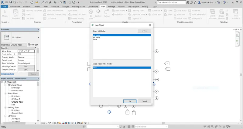
- Name the sheet as required and to go insert option and click on image option and insert image on to the sheet.
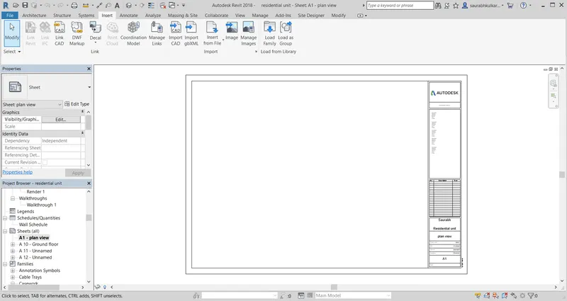
- The required sheet template are obtained -
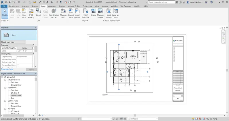
- a. A 101- Ground Floor Architecture Plan
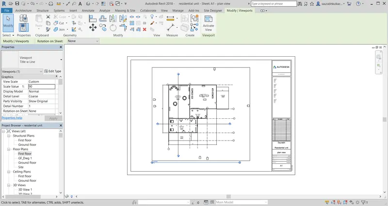
- b. A 102- First Floor Architecture Plan
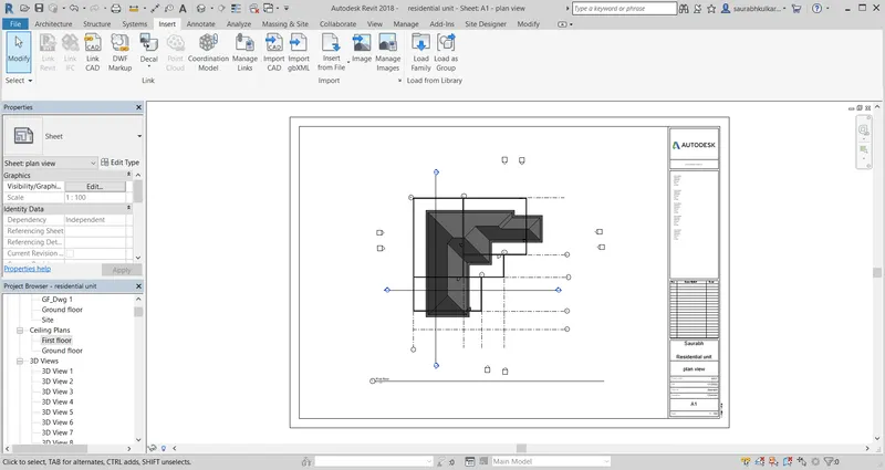
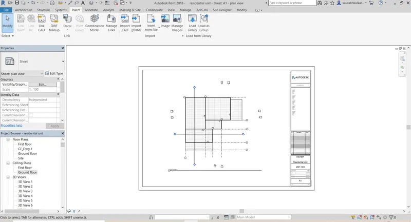
- c. A 103- Roof Plan
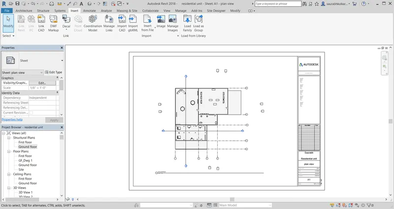
- S 101- Ground Floor Structural Plan
- S 102- First Floor Structural Plan
- S 103- Roof Framing Plan
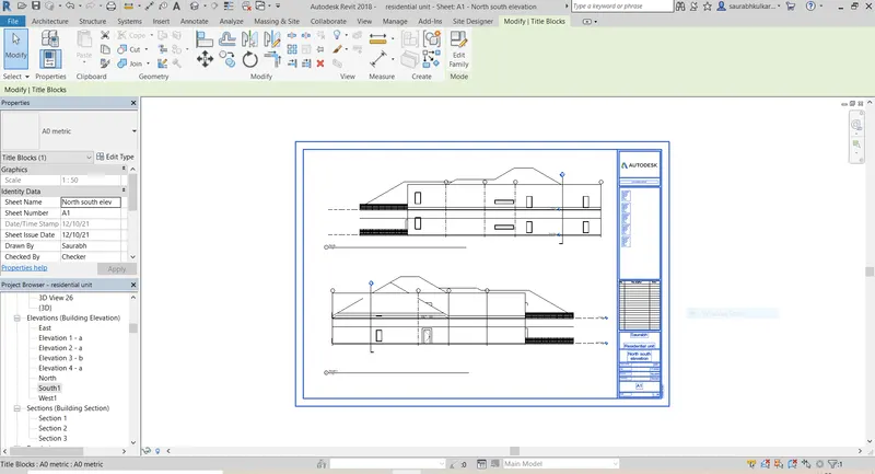
- A-201- North-South Elevations
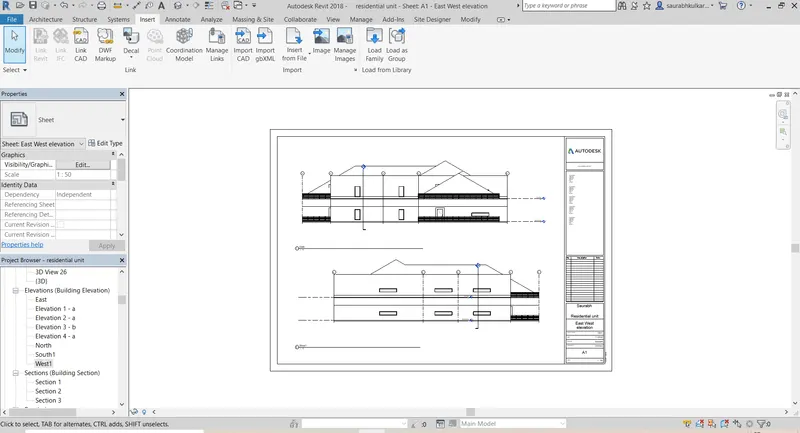
- A-202- East-West Elevations
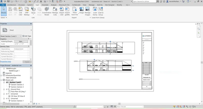
- Section 2 and 3 plan view
- Question no.10
- Aim - To create camera views and sheets naming A 501, 502 etc.
- Introduction - The tools used as view tab, 3d view, camera view. Here we use camera option to views in the 3D views.
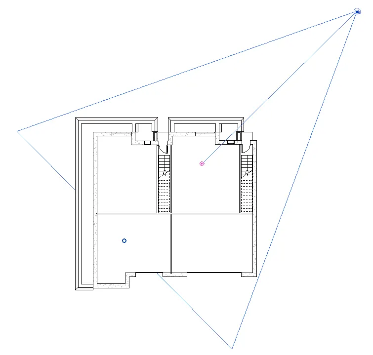
- Move the camera to change the view. Open the 3D view. In the Project Browser, right-click the 3D view name, and select Show Camera. The camera is selected in all views where the camera is visible, such as plan, elevation, and other 3D views. You can place a camera by activating it from your ribbon, View tab, Create panel. Click the small arrow near the 3D view, and click the camera button on the drop-down menu.
-
Selected camera in plan view
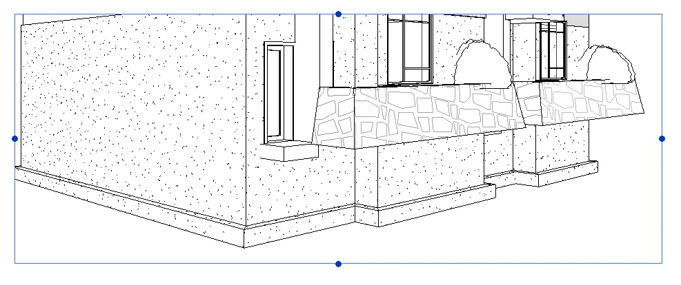
Selected camera in 3D view
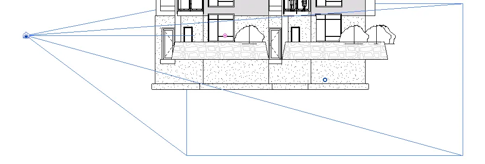
Selected camera in elevation view
- In the Project Browser, double-click the view in which you want to modify the camera position (for example, the plan view or the elevation view).
- Drag the camera to move it. The view updates according to the new camera position. Use an elevation view to change the height of the camera position, or in the Properties palette for the 3D view, modify the Eye Elevation parameter.
- Drag the target to move it. The view updates according to the new target point. Use an elevation view to change the height of the target position, or in the Properties palette for the 3D view, modify the Target Elevation parameter.
- Select the 3D view. Drag the handles to vary the field of view (FOV).
- Process -
- In the 3D view of view tab click on camera view and set it as required to see camera view.
- In the same way as we did above create new sheets and paste the camera views in the sheets.
- A 501 Living area
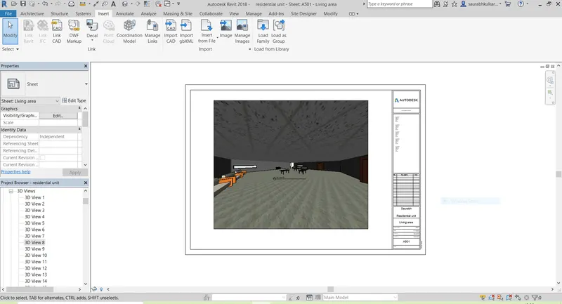
- A 502 Drawing room
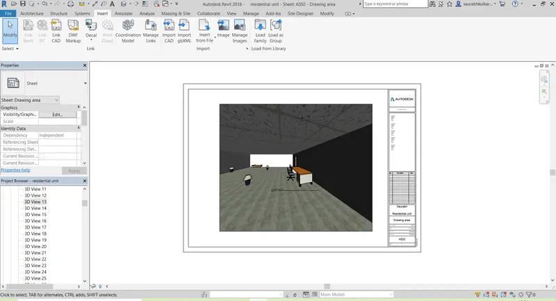
- A 503 Bed room
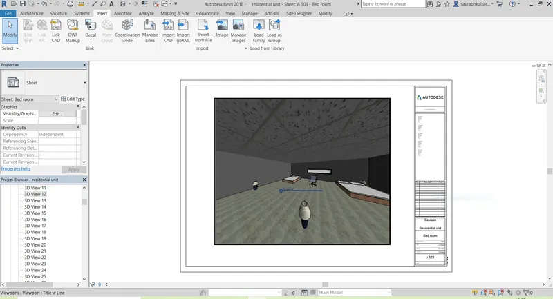
- A 504 Bathroom
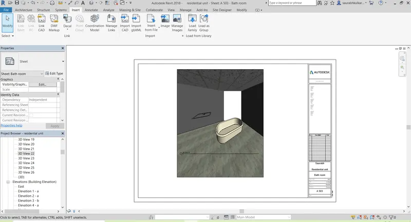
- A 505 Kitchen
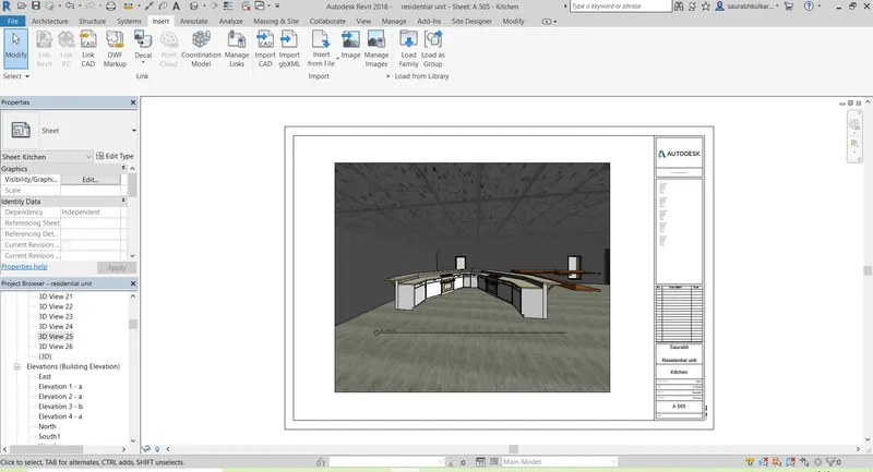
- A 506 Dining Room
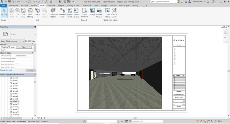
- 507 Rest room