To calculate the dead , live and wind load for RC residential structure and to apply them using TSD
- Que no.1
- Ans -
- Aim - Calculate dead load in design report based on IS code and apply dead load on the model
- Finishes of 50mm.
- Slab thickness as per the design
- Brick wall load
- Roofing load
- Tools/Required:
- Excel sheet
- Calculator
- IS code
- Dimension
- For applying load
- Tekla software
- File
- Open
- Load
- Load cases
- Load Combinations
- Area Load
- Validate
- Project Window
- Property Browser
- Seen Content
- Process -
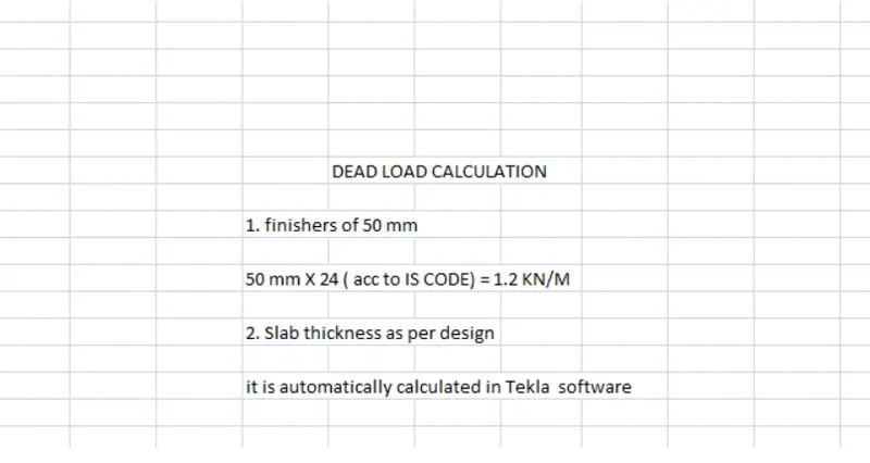
- 1.Finishers of 50 mm.
- 50 mm x 24 (acc to IS code) = 1.2 Kn/m.
- 2.Slab thickness as per design
- It is automatically calculated in Tekla software.
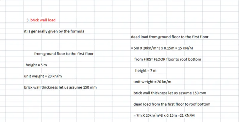
- 3.Brick wall load
- It is generally given by formula
- = Height x Unit Weight x Brickwall Thickness
- From ground floor to first floor
- Height = 5m.
- Unit weight = 20 kn/m.
- Brick wall thickness let us assume 150 mm.
- Dead load from ground floor to first floor
- 5 x 20 kn/m^3 x 0.15 = 15 Kn/m.
- From first floor to roof bottom
- height = 7m.
- unit weight = 20 kn/m.
- brick wall thickness let us assume 150 mm.
- dead load from first floor to roof bottom
- 7 x 20 kn/m^3 x 0.15 = 21 kn/m.
- 4. Roof wall loading
- Check for slope of roof in or model it is 0 degrees
- For every rise in 10 degrees we must reduce load acting by 0.02.
- as per IS code we are going to apply an area load of 1.5 kn/m^2.
- 15-0x0.02 = 1.5 kn/m.
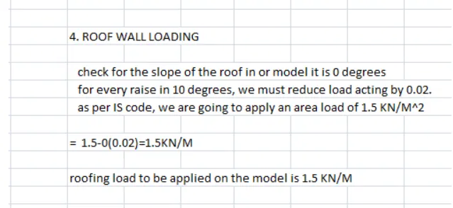
- Roofing load to be applied on model is 1.5 kn/m.
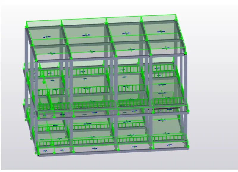
- Applying dead load on model for that
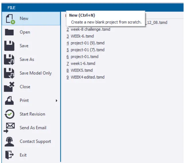
- 5. open the saved file icon present in the file toolbar
- 6. Click on load option and select load cases icon.
- 7. A dialog box appears check for the dead load if it is not there add it.
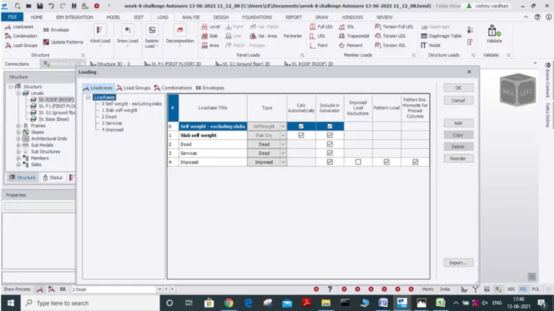
- 8. Now generate load combinations by selecting generate option and select required load combinations.
- 9.Then go to load icon and from the drop down box select dead load for finishers.
- Select area load apply on construction level and using property window assign the value which we got by calculations 1.2 kn/m.
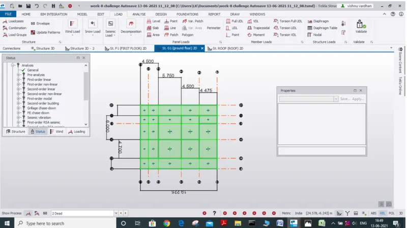
- 10. For brick wall loading select load type as full udl load and according to our calculated values apply it for both the first floor as well as ground floor
- For ground floor to first floor brick wall load to be applied is 15 kn/m.
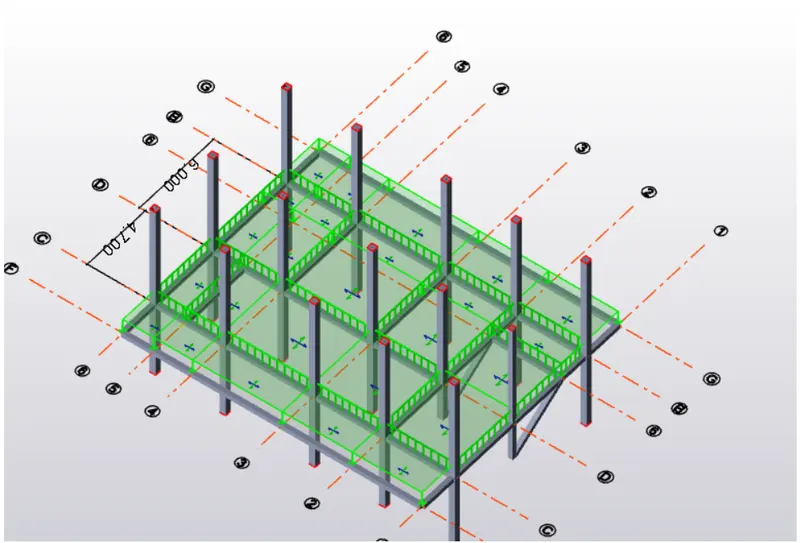
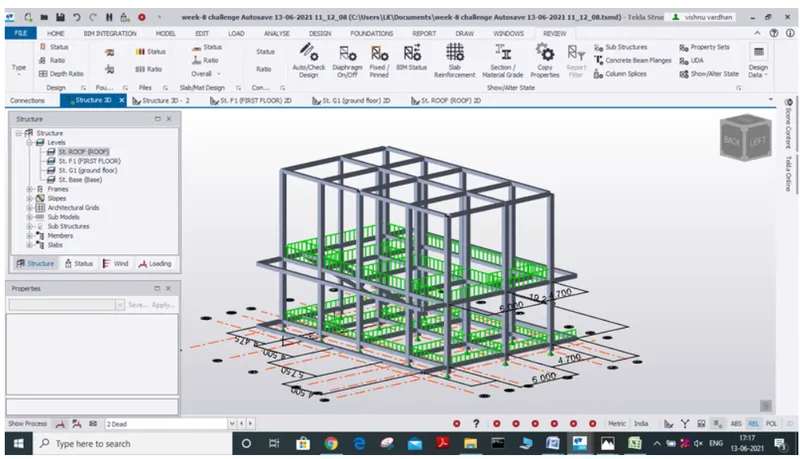
- For first floor to roof bottom.
- Brick wall load to be applied is 21 kn/m
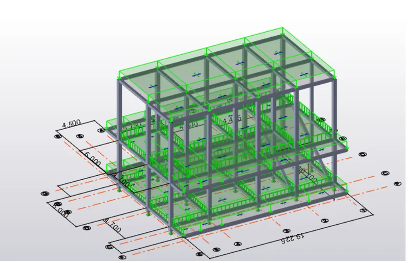
- 11.Now let us apply roof load
- Select area load option and go to roof with help of project window and by assigning the load as 1.4 kn/m.
- Result -
- applied dead load successfully
- Que no.2
- Ans -
- Aim -
- Calculate live load in design report based on IS code and apply dead load on the model.
- Tools required -
- File
- Open
- Load cases
- Load Combinations
- Validate
- Project Window
- Property Browser
- Seen Content
- IS code
- Area load
- Process -
- Calculation of live load in design report based on IS code
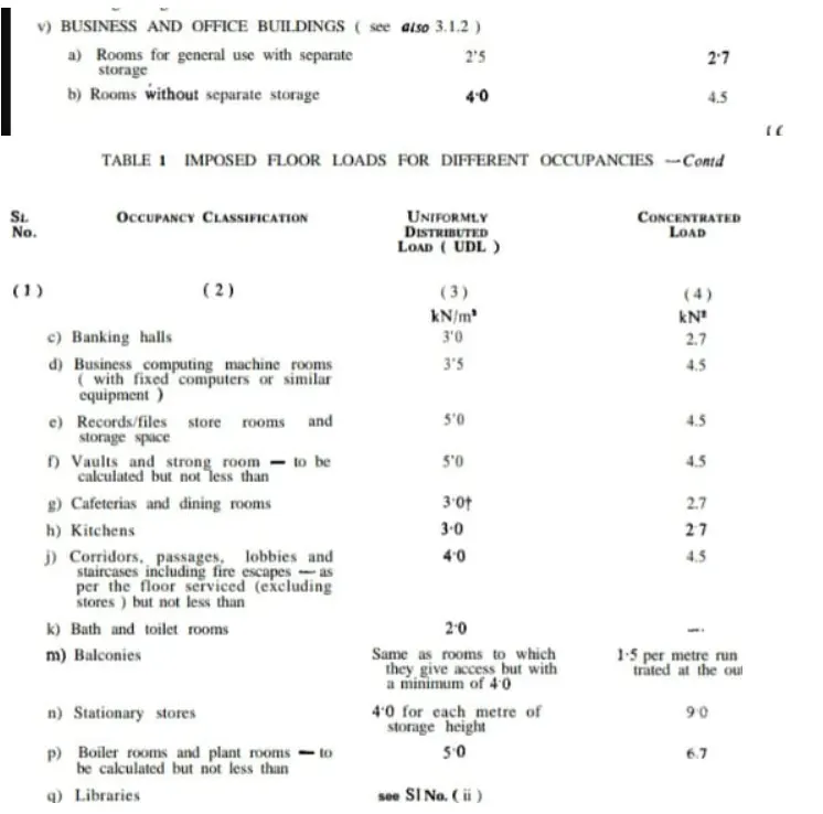
- based on purpose that the room serves IS code has given some standards
- IS 875 part 2
- Applying live load on the model
- 1. Open the saved file in Tekla software using open icon present in the file toolbar
- 2. Select load icon present in the load toolbar and add a new load in the type of load as imposed load.
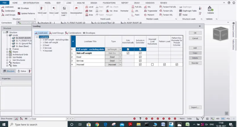
- From drop down box select load as live load
- 3. Now select area load and according to the defined value as per IS code and assign load value acc to purpose it serves.
- to say let us apply live load for corridor say let us select area load now assign load as 4.5 kn/m.
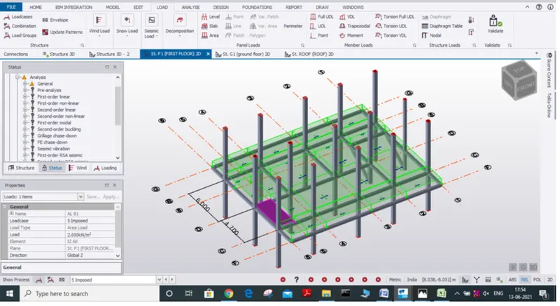
- In the same way we can do it for the remaining rooms as per the mentined values above given (as per IS 875 part 2) apply load in both ground floor and first floor
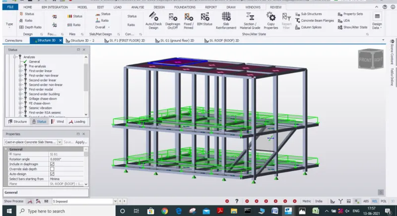
- Result -
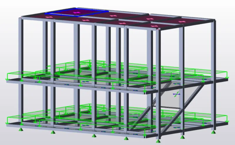
- we have calculated live load in the design report based on IS code value and applied live load to our model
- Que no.3
- Ans-
- Basic wind speed = 50 m/s
- Terrain category 2
- Aim - To generate manual wind loading in the design report based IS code as per the following input
- Basic wind speed = 50 m/s
- Terrain category 2
- Tools required -
- Excel sheet
- Calculator
- IS code
- Dimension
- Process -
- 1. For performing wind load calculation let us make use of excel sheet so let us open excel sheet
- 2. Now let us assign the given details
- Basic wind speed = 50 m/s
- Terrain category 2
- 3. Now let us find out the dimensions of model using the dimension icon and note down in the sheets
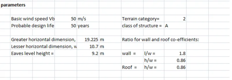
- 4.Now let us find the coefficiant K1, K2, K3, K4
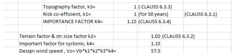
- 5. Now after calculating K1,K2,K3,K4 we can calculate design wind speed followed by design wind pressure formulae
- Vz = Vb x K1 x K2 X K3 X K4
- Pz = 0.6 VZ^2.
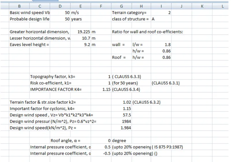
- Now with the dimension Found we have to calculate ratio for wall and roof coefficiants
- 6.With these coefficiant we will find pressure coefficiant by reffering to IS code
- 7.Now with the help of these we will calculate wind load to be applied in each face of structure
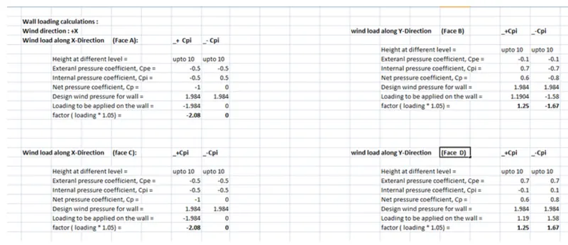
- Result -
- We generate manual wind loading in the design report based IS code as per the following input
- Basic wind speed = 50 m/s
- Terrain category 2
- For all the faces of model by making some assumptions and details from model
- Que no.4
- Ans -
- Based on above calculation apply the loading on the model
- Process -
- 1. Open the saved file in Tekla software using open icon present in the file toolbar
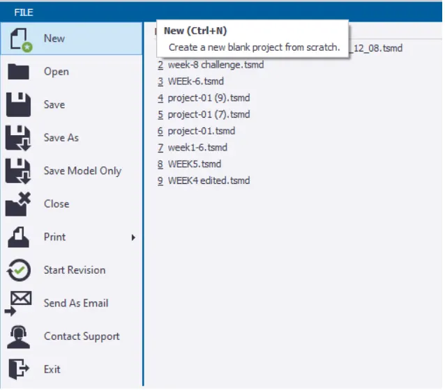
- 2.Now select load cases icon and add 4 loads and assign them to wind load and name them as
- Wind + Y + Cpi
- Wind + Y - Cpi
- Wind + X + Cpi
- Wind + X - Cpi
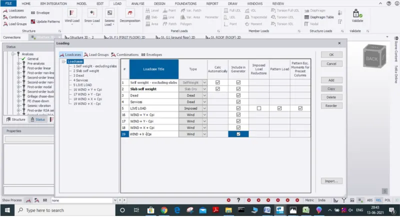
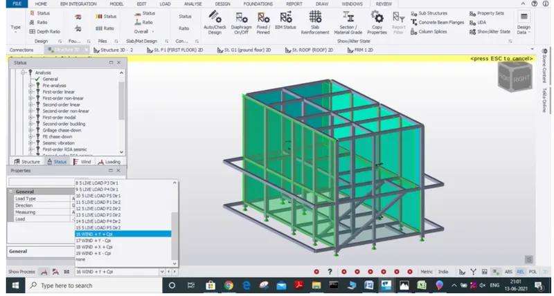
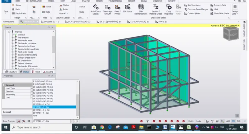
- 3. Now from the dropdown box select load as any one of the created wind loads say Wind + Y + Cpi
- 4. Now select area load option
- 5. For the following load group change the alignment to globel y direction and assign the value of load from calculations for face that is selected
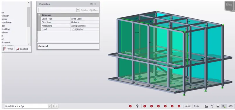
- 6. In the same way apply the load wind + Y + cpi for other face that is along y axis
- 7. Similarly apply wind + Y - cpi load.
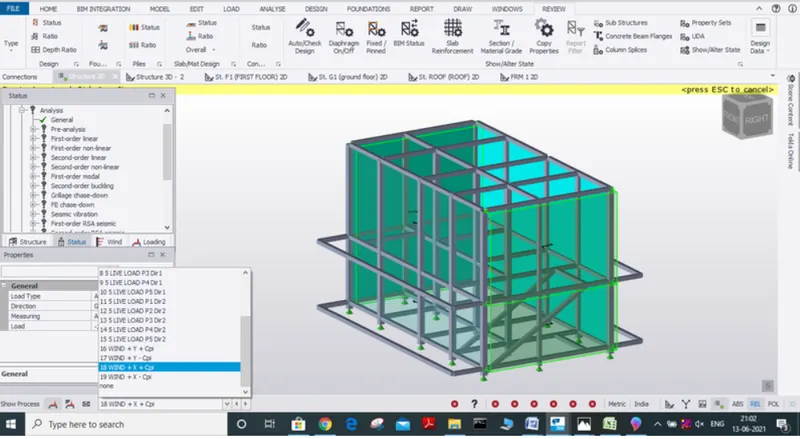
- 8. Similarly apply loads on the face that are along the faces of x axis.
- 9. We can also make use of the frame icon to apply wind load and check how the wind load acting is it acting away or towards the structure
- Result -
- We have successfully applied wind load on our model as per IS code with the help of calculations of wind load which was performed earlier the application of wind load to our calculations to our model is