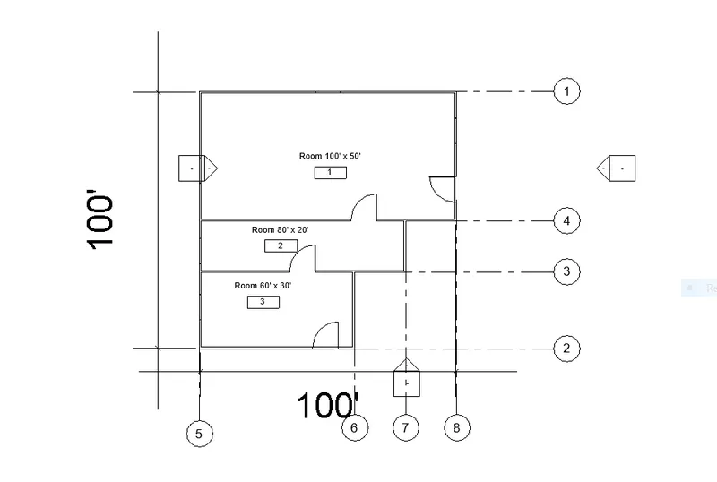
Creating Levels, Grids, Layout and model elements for a residential unit using REVIT
- 1 - What is BIM? Summarize the features of BIM and benefits of using BIM over 2D CAD tools.
- Aim - To find BIM concept. To explain about BIM.
- Introduction - BIM is building information modeling. BIM gives information related to the drafting of revit units. BIM is concept analysed by knowledge of it. Building Information Modeling (BIM) is a digital representation of physical and functional characteristics of a facility. A BIM is a shared knowledge resource for information about a facility forming a reliable basis for decisions during its life-cycle; defined as existing from earliest conception to demolition
- Process -
- BIM helps architectural, engineering and construction professionals to improve the way they design, construct, opeate using tools which are more useful and increases efficiancy. It enables data sharing about building to all parties and any party can change required changes. BIM allows sharing of information through a mutually accessible space known as common data enviroment (CDE). Using this changes can be made at all stages of building from starting to operation and even renovations and renewals. BIM levels start with 0 and go up to 3D,4D,and 6D BIM.
- Benefits of using BIM over 2D CAD tools -
- We can work in 3D,4D,5D or even 6D wheareas in 2D cad only 2D can be viewed. BIM is the newest one out of BIM and CAD, it has more advance features. Main benifit is that BIM is multi user interface where CAD is single interface so, any changes can be done easily and accurately throughout the project. Resource tracking also be done in BIM.
- BIM is not CAD, nor is it intended to be. CAD is a replacement for pen and paper, a documentation tool, and CAD files are basic data consisting of elements that are lines, arcs, and circles—and sometimes surfaces and solide that are purely graphical representation of building components. Moreover, early definitions asserting that BIM is basically a 3D model of a facility are incorrect and do not reflect the truth, nor do they adequately communicate the capabilities and potential of digital, object-based, interoperable building information modeling processes and tools and modern communications techniques.
- 2 - Understand the concept of Categories, Families, Elements, Instances in Revit. Go to Insert Tab, choose a category. Pick a family and element. Understand the instances and insert it to Revit model.
- Aim - To gives the concept of categories, families, instances in revit.
- Introduction - Concept of categories that takes in to account while using revit. There are categories no. and its uses to it. Families are the doors, windows or structure, mechanical family.
- Process -
- We can classify all Revit families into three different types; system families, loadable families, and in place families.
- Even if you are completely new to Revit, you have no doubt discovered how important families and the family editor are to your success in Revit. Everything you create in Revit is part of a family consequently, understanding families and what it takes to manipulate them is a vital part of learning the software. Beginning with the difference between System and Component families, this section will explore the critical concepts and terminology.
- We’ll also take a quick look at what is provided in the Revit libraries and learn about family templates. Following this brief introduction to terminology, the tutorial will focus on the component family creation procedures and strategies presented in detailed step-by-step procedures. Using the concepts and techniques covered herein, you will learn how to begin tapping into one of the most powerful aspects of the Revit software package the Revit Family Editor.
-
Element — Anything in your Revit Architecture project. (Elements in italic can be created and edited in the family editor.)
Model Element — Something that represents the actual geometry of your building.
Host Element — An element that can receive or support or provide structure for other model elements (built in-place construction).
Component Element — An item inserted into a project (items that are pre-manufactured, purchased and installed). Can be freestanding or require a host.
Host Based Component Element — A Component Element that must be inserted on or into a Host.
Freestanding Component Element — A Component Element that can be inserted independently without a Host.
View Element — An item in the Revit interface that allows you to see and interact with all other elements. Views conform to the characteristics of typical architectural drawing types like plan, section, elevation and schedule. Some View Element families allow customization of Types, many do not.
Datum Element — Include Levels, Grids and Reference Planes. These are used establish project context, limits, extents and the like. Datum Elements provide guidelines and limits for other elements within a project and can also include annotative qualities. The families and types of datum elements cannot be edited.
View-Specific Element — Something that is used to document, describe or embellish a view of your project. View-specific elements do not appear in any other views automatically. If you wish to repeat view-specific items in other views, you can copy and paste them.
Detail Element — A two-dimensional family typically representing a model element but at a level of detail that would be impractical to model. Detail elements appear only in the view in which they are added. Detail Elements remain their actual size as created and do not adjust scale with the view.
Annotation Element — Include text, dimensions tags and symbols. These items are view-specific (appearing only in the view in which they are added) and are used to notate, embellish, describe and document design intent within a Revit Architecture project. Annotation elements maintain a constant size relative to the plotting scale of the view in order to maintain a constant size relative the sheet on which they are placed. Level and Grid head tags, Section and Elevation head tags, model element Tags and Symbols (Generic Annotation families) can be created and modified in the family editor. Text and Dimensions cannot.

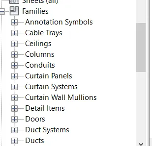
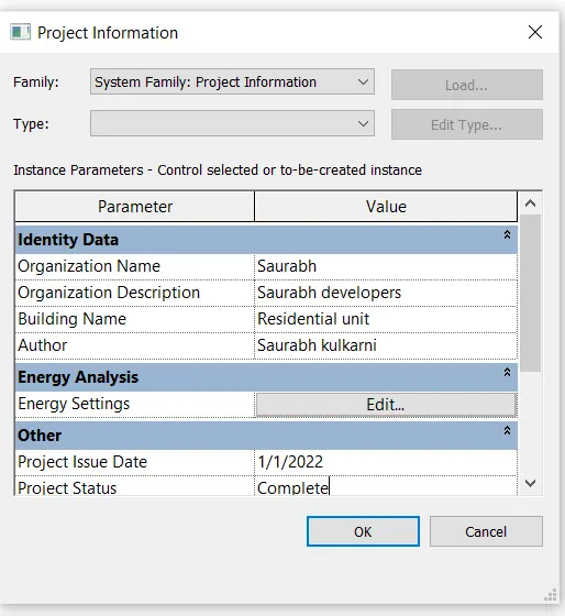
- 3 - Setting up a Project – Open a project file with architectural template. Save the file with appropriate name. Set up the project units to Imperial / Metric based on your convenience of modelling. Complete the project information under Manage tab. Set up the maximum backups for project file to 3.
- Aim - To provide setting project and also gives project information.
- Introduction - In this we inform the project information. We provide the architectural template with new project.
- Complete the project information with toolbar.
- Process - Here we first the open new project with architectural template.

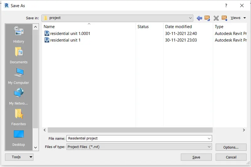
- Save the project as residential project.
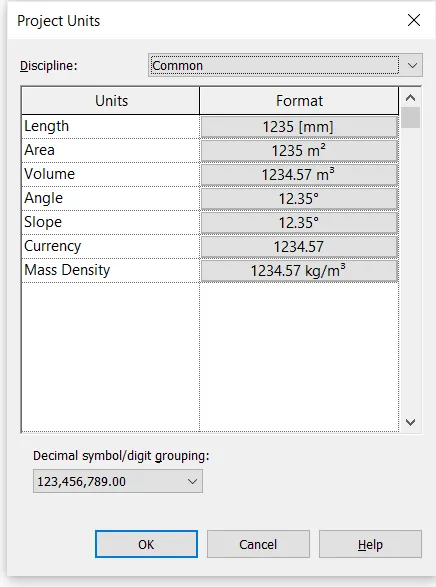
- Setting up the units with project based.
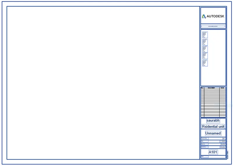
- Provide information to project models.
-
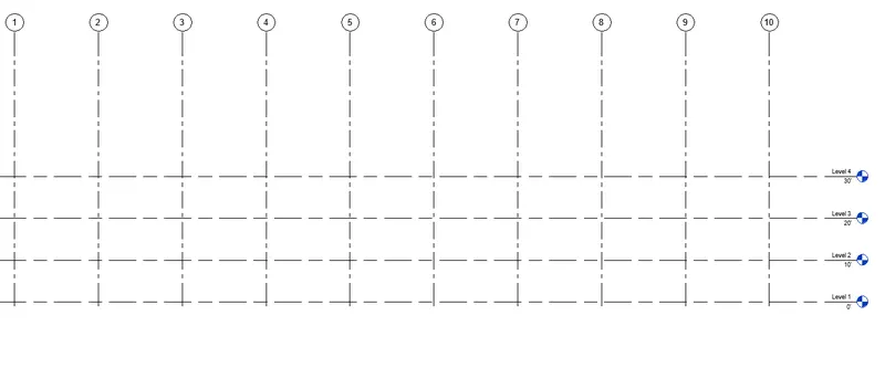
4 - Understand the concept of Levels and Grids. Follow the naming and conventions. Create the following Levels: (Convert to metric equivalents if metric is your units)
Ground Floor @ 0’
First Floor @ 10’
Second Floor @ 20’
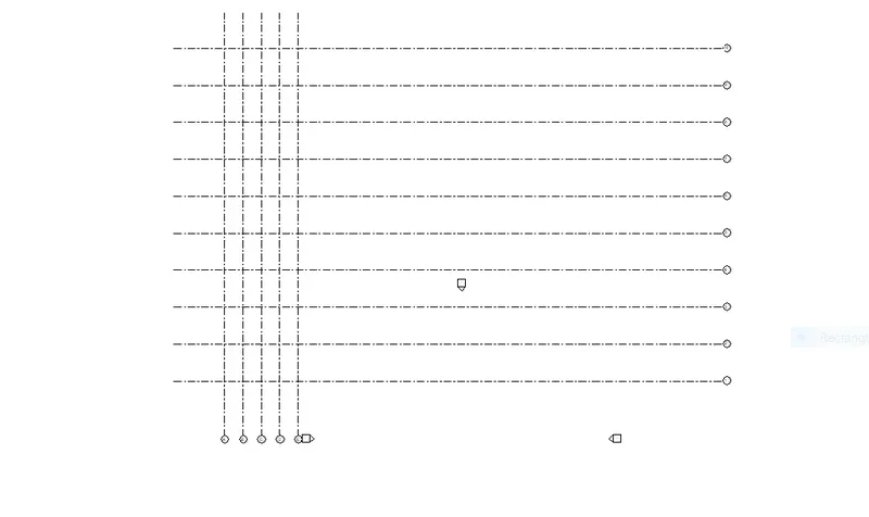
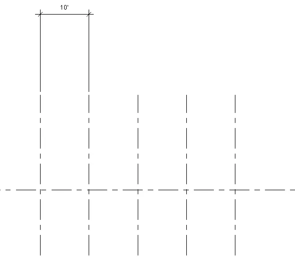
Roof @ 30’ Grids Transverse Grids A, B,C,D, E @ 10’ spacing
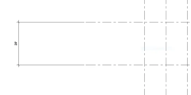
Longitudinal Grids from 1 to 10 @ 20’ spacing - Aim - To provide grids and levels.
- Introduction - Here we understand the concept of grids and levels. A grid is a collection of horizontal and vertical lines creating a pattern against which we can line up our design elements. They help us to create layouts in which our elements won't jump around or change width as we move from page to page, providing greater consistency on our websites. The grids are 3D element that are visisble in 3D views to intersect extents.
- Levels - Grids and levels are displayed at each level of the building and are configured by default in relation to your camera position. For example, if you are standing on Level 2 of your building model, then the grid will be displayed in green on the floor below you, and displayed in red on the floor above you.
-
When creating a grid in Revit, it is more efficient to use the Offset option while creating a new Grid line, rather than the copy command, unless you only want a Reference view and not a Floor or Ceiling plan view. If you use copy to create a new view and you decide that you do ultimately need a floor or ceiling plan, then you will need to us the Plan View tool on the View tab to generate the view for a floor or ceiling plan.
When creating Levels and Grids it is a good idea to draw your levels first to ensure that your grid lines pass through all the grids lines that your project needs. If you add a Level after your Grid lines and the new Level is beyond the 3D bubble of your Grid line, it will not show up on the associated plan view levels.
- Process -
- Go to grids add grids as per given.
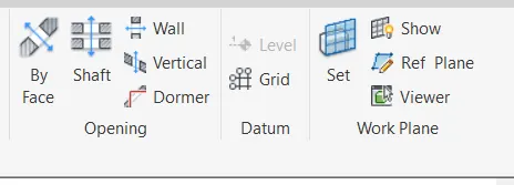
- Add grids and levels as per given with grid and level toolbar.
- 5 - 3D modelling of residential unit – From looking at your house / or a place you aspire. Create a conceptual layout of the residential unit. You can measure using a tape or
you can access your residential plan to create a similar layout. - Aim - To draw residential unit.
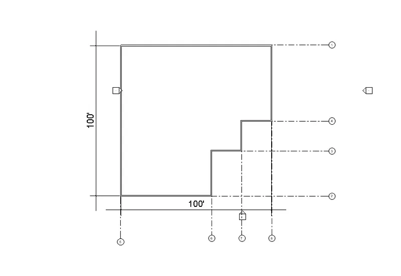
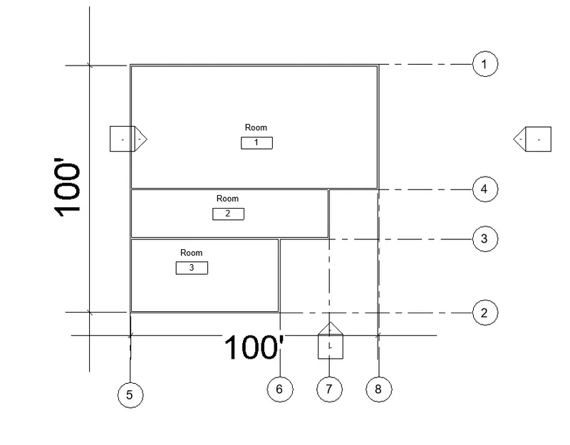
- Introduction - Here we can drafting of residential unit layout. The dimensions of it as per taken in to account. There is one layout we draw to as residential unit of size 100 x 100 ft.
- Process -
- Go to revit -> open new project -> choose architectural template.
- Save file as residential unit.
- Go to wall toolbar -> choose architectural toolbar.
- Draw wall layout of size.
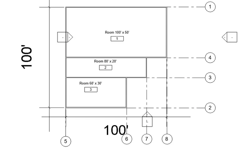
- 6 - In the layout created draft the level of details you are planning to include – Dimensions of room, components you plan to add in the residential unit.
- Aim - To create a layout with addition of rooms and components.
- Introduction - Here we provide rooms in layout. There one residential unit which create rooms of various sizes.
- The other components also includes with rooms. Rooms are nothing but enclosed area with specific boundary.
- Room divide the layout of unit in to parts.
- Process -
- Go to room toolbar.
- Add room at enclosed area.
- Rename it as hall or kitchen etc.
- add room dimensions.
- 7 - Identify the residential model elements such as Door, Windows, Tables, Chair, Couch, Bed, Lamps from the library and insert them to the model . Save the project for use
for Assignment 3. - Aim - To indentify model elements and insert it.
- Introduction - To model the element such as doors, windows, tables, chair etc are used in residential unit. These are components of unit to specifies the model into required shape.
- Process -
- Open the revit model -> Go to families -> Use the elements such as door, window, tables, chair.
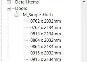
- Door - Door is component of modelling unit which requires different materials of it.
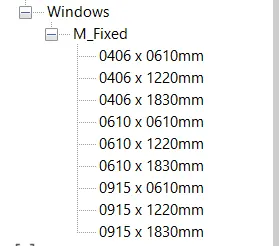
- Window - Window is component of model which gives the exact location of it. On which room it is located. It is located at specific height.
- Tables - Tables are unit of room. It is located in the particular space. Used to place the things on it.
- Chair - Chair is seating arrangement in the room. Some people or resting some items in the room chair is used.
- Bed - Bed is used for sleepin purpose at night.
- Lamps - Lamp is a lightning element in dark place. Lamps provides clear visibility at night time.
- Load revit family -> choose elements and add it on model.