Project 1
- Project no 1.
- Ans -
- Files and snaps are attached below.
- Aim - To model and design of praposed coil centre chennai using staad pro.
- Introduction - Here we model the coil centre using given data. We can design using design parameters praposed coil centre. Coil centre is truss frame structure. This can be design as per staad pro process. We can purlin weight, rail weight, gantry girder weight for calculation purpose.
- Gantry girder - The gantry girders are girders which supports the loads that are transmitted through the travelling wheels of the crane. The crane girder spans from column to column, this usually do not have any lateral support at the intermediate points excepting when a walkway is formed at the top of the girder. The crane girder spans from column to column, this usually do not have any lateral support at the intermediate points excepting when a walkway is formed at the top of the girder. Overhead traveling cranes are used in industrial buildings to lift and transport heavy jobs, machines, and so on, from one place to another. Aiso use IS 800 2007.
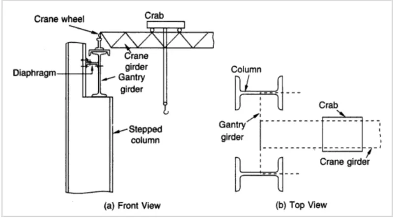
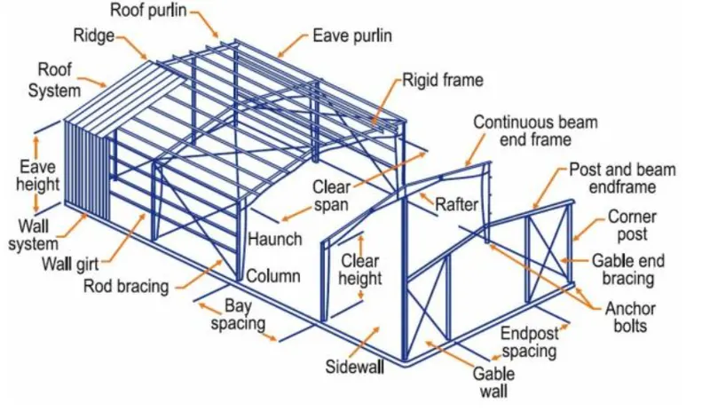
- Purlins - In steel construction, the term purlin typically refers to roof framing members that span parallel to the building eave, and support the roof decking or sheeting. The purlins are in turn supported by rafters or walls.
- The purlins of a roof support the weight of the roof deck. The roof deck is the wood panel, ply board, or metal sheeting that creates the surface of the roof. When made of wood, it is usually covered with some sort of weatherproofing and sometimes an insulation material.
- Several kinds of purlins exist. They are divided into categories based on the material from which they are made and their shape. Different purlins are used for different purposes, including structural support of walls or floors. Purlin is important because without it, there’s no frame for the sheeting on the roof to rest on, making purlins critical to the structure of the roof.
- Dead load - a constant load in a structure (such as a bridge, building, or machine) that is due to the weight of the members, the supported structure, and permanent attachments or accessories. The dead loads are calculated from the member sizes and estimated material densities. Unit weight of building materials can be estimated in accordance with IS : 875 (Part 1).
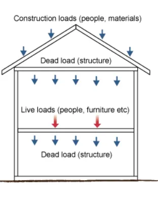
- Live load - Live load is a civil engineering term that refers to a load that can change over time. The weight of the load is variable or shifts locations, such as when people are walking around in a building. Anything in a building that is not fixed to the structure can result in a live load, since it can be moved around. Live loads are factored into the calculation of the gravity load of a structure. Use IS : 875 (Part 2).
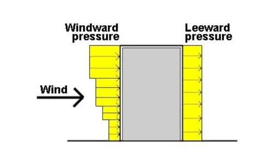
- Wind load - Wind load is the load, in Kilonetwon per metre foot, placed on the exterior of a structure by wind. The angle at which the wind strikes the structure. The shape of the structure (height, width, etc.). Use IS : 875 (Part 3)
- Wind exerts three types of forces on a structure:
- Uplift load - Wind flow pressures that create a strong lifting effect, much like the effect on airplane wings. Wind flow under a roof pushes upward; wind flow over a roof pulls upward.
- Shear load – Horizontal wind pressure that could cause racking of walls, making a building tilt.
- Lateral load – Horizontal pushing and pulling pressure on walls that could make a structure slide off the foundation or overturn. High wind pressures can collapse doors and windows, rip off roofing and roof decking and destroy gable end walls. Roof overhangs and other features that tend to trap air beneath them, resulting in high uplift forces, are particularly susceptible to damage. Broken windows and doors can expose the building contents to serious damage from internal wind pressures and water entry.
- Given -
- Design only a Main Frame with Lean (Grid 2) & Gable Frame without Lean (Grid 15)
- Assume purlin load as 8.77 kg/m = 0.086 KN/m.
- Assume Gantry girder wt. = 158.24 kg/m = 1.55 KN/m.
- Assume Rail weight = 53 kg/m = 0.5179 KN/m.
-
Building Parameters: -
1
Building Width
30000.00 mm
Client
Out to Out of Steel
2
Width Module
Clear Span
Client
3
Building Length
140000.00 mm
Client
Center to Center of Steel Column
4
Building Height
11100.00 mm
Client
Clear Height from FFL
5
Roof Slope
1:10
Client
6
Column Base
Fixed Base
Assumed
To control Deflection
7
Bay Spacing (in mm)
Main frame with Rafters
14@10000
Client
Center to Center of Steel Column
8
Roof Bracing
Diagonal Angle Bracing
Client
9
Wall Bracing
Portal Bracing and above Angle Bracing
Client
Up to 6.5m Portal Bracing
10
End Wall Type
Rigid Frame
Assumed
-
GENERAL PARAMETERS
Loads & Design
1
Dead Load
0.14 KN/m2
Assumed
2
Coll Load
0.15 KN/m2
Client
False ceiling load for Roof extension alone
3
Live Load
0.75 KN/m2
Code
IS 875 (Part 2) -2015
Sl.No
Parameter
Value
Data From
Remark
4
Wind Load
Wind Speed
180 KMPH
Code
IS 875 (Part 3) - 2015
K1 =
1.00
Code
IS 875
(50 years of mean probable design life
K2 =
0.94
Code
IS 875
(Terrain Category 3)
K3 =
1.00
Code
IS 875 (Upwind slope is less than 3°)
K4 =
1.15
Code
IS 875 (Cyclone Zone)
Building Condition
Medium Permeability
Code
IS 875 (Part 3) - 2015
Wind co-efficients calculated as per
Code
IS 875 (Part 3) - 2015
5
Seismic Zone
Zone III
Code
IS 1893-2015 (Part 4)
6
Loads applied as per
IS 875 - 2015
Client
7
Primary Member design
IS 800 : 2007
Client
8
Cold Form Design
AISI 2001
Assumed
- Process - for main frame and gable frame.
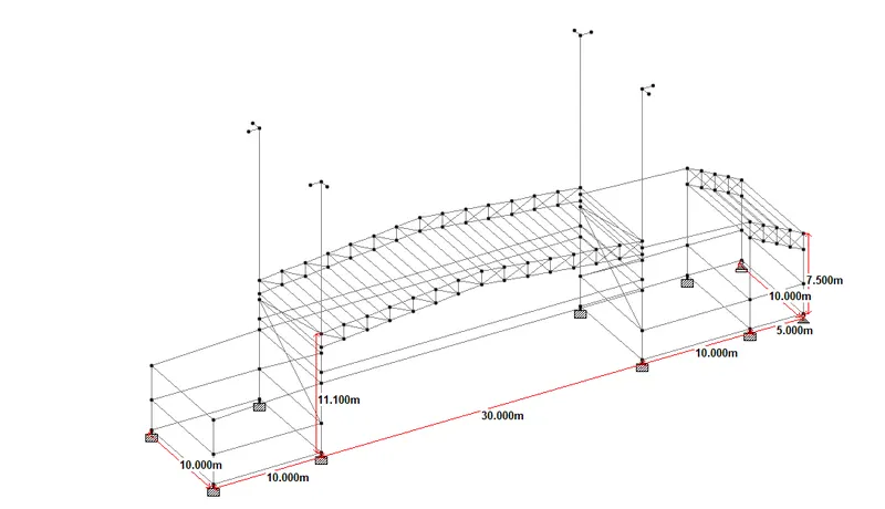
- Open staad -> define nodes and beams as per given data -> Go to translation assign bay specing.
- For Area 1 - 30 m width.
- roof slope = 1/10 = 0.1.
- Height of roof in top level = 1.5 m.
- Add walls -> Add wall sheeting -> add roof sheeting.
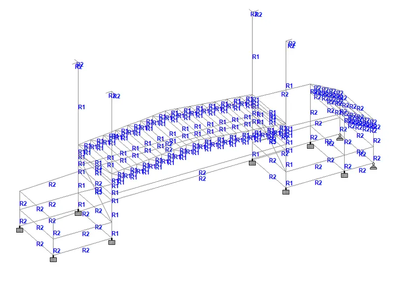
- Add properties -> go properties section database -> add and assign section to structure.
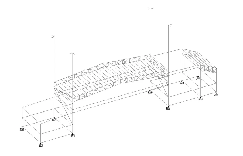
- Go to support -> create support -> add and assign support -> fixed base and pinned base.
- Go to loading -> add load defination and load case details -> assign loads to structure.
- Total D.L. =
- 0.086 + 1.55 + 0.5179 = 2.15 KN/m.
- 0.15 x 30 = 4.5 KN/m.
- 0.15 x 10 = 1.5 KN/m.
- 0.15 x 5 = 0.75 KN/m.
- Total D.L. = 4.5 + 1.5 + 1.5 + 0.75 = 8.25 KN/m.
- Total L.L. = 0.75 x 30 = 22.5 KN/m.
- 0.75 x 10 = 7.5 KN/m.
- 0.75 x 5 = 3.75 KN/m.
- Total L.L. = 22.5 + 7.5 + 3.75 + 7.5 = 41.25 KN/m.
- Total Coll load = 0.15 x 30 = 4.5 KN/m.
- Total wind load =
- 184 KMPH = 50 m/s.
- Internal pressure coefficiant = +/- 0.5 .
- External pressure coefficiant =
-
0 degree
0 degree 90 degree 90 degree EF GH EG FH -0.9 -0.4 -0.8 -0.4 - As per given data
- Design wind speed = Vb x k1 x k2 x k3 x k4.
- = 50 x 1 x 0.94 x 1 x 1.15.
- = 54.05 m/s.
- Wind pressure = 0.6 x 54.05^2.
- = 1.75 KN/m^2.
- as per IS 875 Wind direction factor kd = 1.
- Area averaging factor ka = 0.83.
- Combination factor kc = 0.9.
- Design wind pressure = 1.75 x 1 x 0.83 x 0.9.
- = 1.307 KN/m^2.
- Wind load = 1.307 x 11.1 = 14.50 KN/m.
- 0+CPI = 14.50 + 0.5 - 0.9 = 14.10 KN/m.
- = 14.50 + 0.5 - 0.4 = 14.6 KN/m.
- 0-CPI = 14.50 - 0.5 - 0.9 = 13 KN/m.
- = 14.50 - 0.5 - 0.4 = 13.6 KN/m.
- 90+CPI = 14.50 + 0.5 - 0.8 = 14 KN/m.
- = 14.50 + 0.5 - 0.4 = 14.6 KN/m.
- 90-CPI = 14.50 - 0.5 - 0.8 = 13.2 KN/m.
- = 14.50 - 0.5 - 0.4 = 13.6 KN/m.
- Seismic load =
- EQ + x.
- EQ - x.
- EQ + z.
- EQ - z.
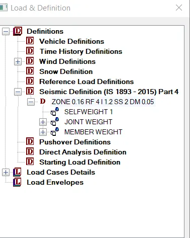
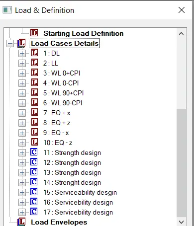
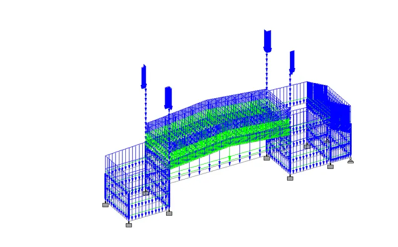
- Add load combinations -> go to load combination add as per strength design and servicebility criteria.
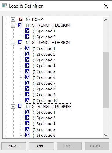
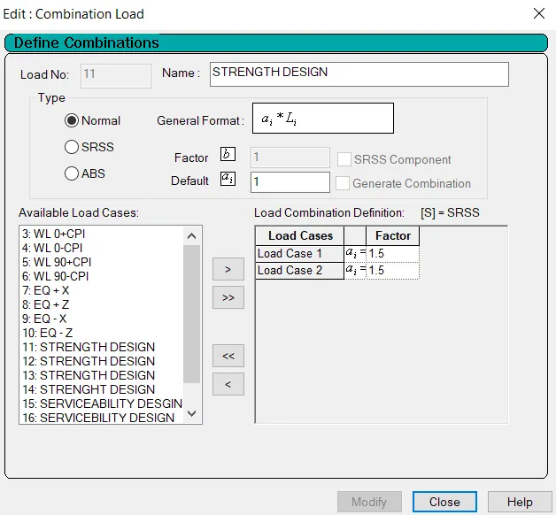
- Go to design -> add design parameters -> Use IS 800 : 2007.
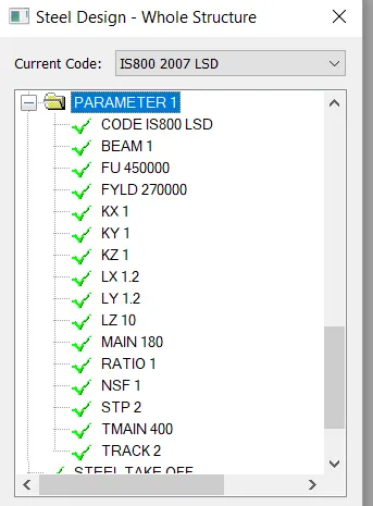
- After run analysis and check deflection and section safe results.
- for gable frame and gable frame.
- Open staad -> define nodes and beams as per given data -> Go to translation assign bay specing.
- For gable frame we analysis and design for one frame.
- For Area 1 - 30 m width.
- roof slope = 1/10 = 0.1.
- Height of roof in top level = 1.5 m.
- Add walls -> Add wall sheeting -> add roof sheeting.
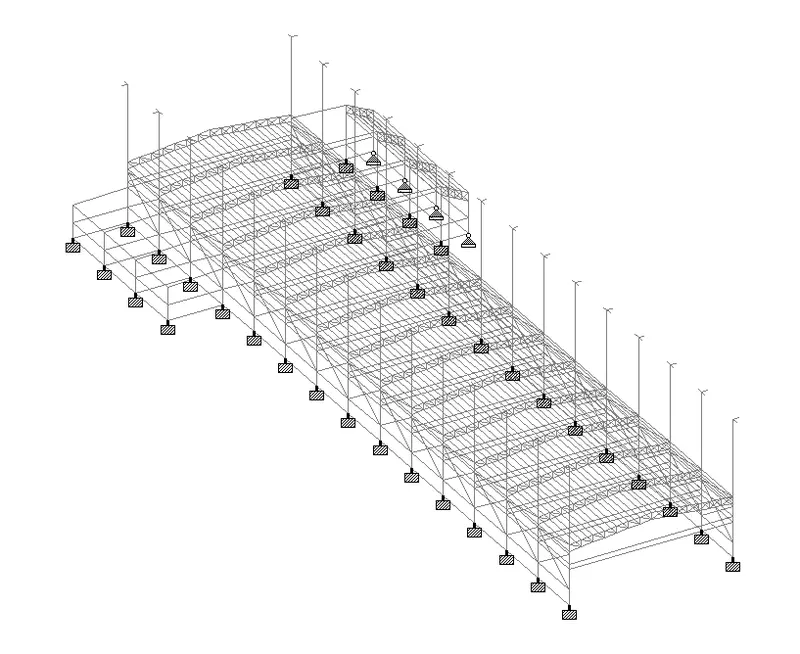
- Add properties -> go properties section database -> add and assign section to structure.
- Go to support -> create support -> add and assign support -> fixed base and pinned base.
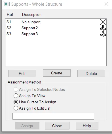
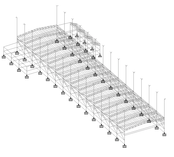
- Go to loading -> add load defination and load case details -> assign loads to structure.
- Total D.L. =
- 0.086 + 1.55 + 0.5179 = 2.15 KN/m.
- 0.15 x 30 = 4.5 KN/m.
- 0.15 x 10 = 1.5 KN/m.
- 0.15 x 5 = 0.75 KN/m.
- Total D.L. = 4.5 + 1.5 + 1.5 + 0.75 = 8.25 KN/m.
- Total L.L. = 0.75 x 30 = 22.5 KN/m.
- 0.75 x 10 = 7.5 KN/m.
- 0.75 x 5 = 3.75 KN/m.
- Total L.L. = 22.5 + 7.5 + 3.75 + 7.5 = 41.25 KN/m.
- Total Coll load = 0.15 x 30 = 4.5 KN/m.
- Total wind load =
- 184 KMPH = 50 m/s.
- Internal pressure coefficiant = +/- 0.5 .
- External pressure coefficiant =
-
0 degree
0 degree 90 degree 90 degree EF GH EG FH -0.9 -0.4 -0.8 -0.4 - As per given data
- Design wind speed = Vb x k1 x k2 x k3 x k4.
- = 50 x 1 x 0.94 x 1 x 1.15.
- = 54.05 m/s.
- Wind pressure = 0.6 x 54.05^2.
- = 1.75 KN/m^2.
- as per IS 875 Wind direction factor kd = 1.
- Area averaging factor ka = 0.83.
- Combination factor kc = 0.9.
- Design wind pressure = 1.75 x 1 x 0.83 x 0.9.
- = 1.307 KN/m^2.
- Wind load = 1.307 x 11.1 = 14.50 KN/m.
- 0+CPI = 14.50 + 0.5 - 0.9 = 14.10 KN/m.
- = 14.50 + 0.5 - 0.4 = 14.6 KN/m.
- 0-CPI = 14.50 - 0.5 - 0.9 = 13 KN/m.
- = 14.50 - 0.5 - 0.4 = 13.6 KN/m.
- 90+CPI = 14.50 + 0.5 - 0.8 = 14 KN/m.
- = 14.50 + 0.5 - 0.4 = 14.6 KN/m.
- 90-CPI = 14.50 - 0.5 - 0.8 = 13.2 KN/m.
- = 14.50 - 0.5 - 0.4 = 13.6 KN/m.
- Seismic load =
- EQ + x.
- EQ - x.
- EQ + z.
- EQ - z.
- Add load combinations -> go to load combination add as per strength design and servicebility criteria.
- Go to design -> add design parameters -> Use IS 800 : 2007.
- After run analysis and check deflection and section safe results.