Project 2 - MODELLING, ANALYSIS & DESIGN OF COMPOSITE STUCTURES IN COMFLOR & ETABS
A 30 - 40hr project on modelling, analysis & design of a state-of-the-art tall composite building using ETABS software. The composite members to be designed using Comflor software.
Key Highlights:
a. Modelling
- The structural model prepared for the project 1to be used for the project 2.
- Prepare two distinct structural framing plans (location of primary & secondary beams) as discussed in Lecture 11.
- Create member definition for the steel sections by importing through library.
- Select deck slab profile and section using the Comflor Manual.
- Modelling of the composite metal deck section in ETABS
- Modelling of the composite columns in ETABS
- Create steel beam, steel column, bracing & core wall properties to be used further in the project.
b. Loadings & Load combinations
- Comflor: Wet concrete and construction loads for the design of deck slab
- ETABS: Use load patterns and combinations created in project 1
- Definition of Pre-composite dead loads
- Define footfall loadings for the vibration checks.
c. Structural Analysis
- Comflor software to be used for the analysis of composite deck slab
- Obtain the shear force & bending moment diagrams for the floor beams and columns.
- Check the gravity load path in the structure if it follows the designer’s intent.
- Perform quick hand calculations to confirm the base reactions for the gravity load cases.
- Check natural frequency for the floor system and mitigate the floor vibration by keeping fundamental frequency > 3Hz.
d. Design of structural members
- Shear studs & Composite deck design calculations
- Interpretation of the design results for the composite beam from ETABS
- Pre-camber criteria and requirements
Key Deliverables:
- Comflor file with the complete modeling of the slab with appropriate loadings
- Comflor report for the composite slab design (as PDF file)
- Submit a ETABS model with the complete model of the composite structure.
- A comprehensive project report from the ETABS software (as PDF file)
ans-
AIM-
DESIGN COMPOSITE HIGH RISE BUILDING USING E TABS .
AND DESIGN COMPOSITE DECK PROFILE USING COMFLOR
SOFTWARE .
Flow chart for composite high rise building analysis and design .
1. architectural plan study and column shear wall position marking .
2.steel beam alingment marking [considering deck span 3-4 meter ]
3.material data and loading details from ASCE -07 CODE .
4.comflor software or catelouge reference for deck design .
5.prepartion of comflor deck design report .
6.calculation of weight of deck [to provided self weight during etabs modelling ]
7.story and grid assignment in etabs .
8.material ,steel beam defination , membrane defination [deck] , composite column defination and concerete
shear wall defination [steel encased concerete column ]
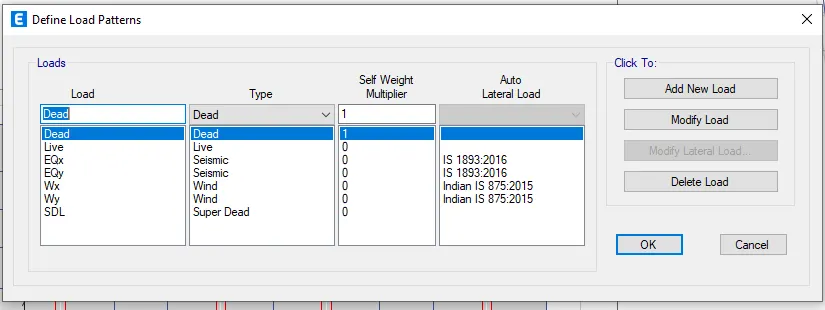
9.load pattern ,lateral load assignment , mass source , response spectrum ,load combinations assignment .
10.modeling of composite column [for gravity load resistance ] ,shear walls [for lateral load resistance ] ,
steel beams and membrane floorsmodeling .
11. provision of loading .
12.analysis and designing model .
verifying all members are passing design [D/C ration for composite column ,
limitstate check state check for steel beam ].
13.varition analysis check with ETABS .
14.Checking deflection of composite beam and provision of camber if required ,.
Architectural plan study & Column shear wall position marking:
The peripheral yellow hatched columns are positioned for gravity load reistance.
The internal green color rc walls and lift area rc walls are planned for laterla load resistance.
The column position & RC wall alignment are sketched according to the partition wall layout,
so that the structural elements will get hidden.
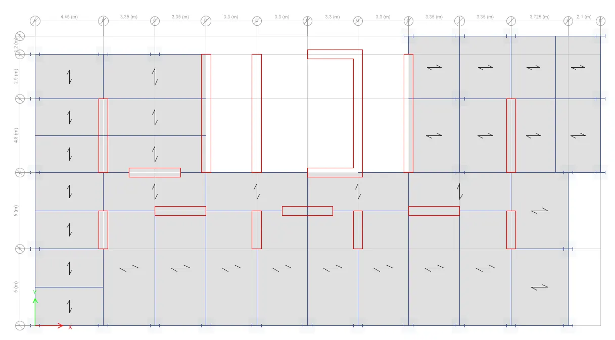
Steel beam alignment marking:
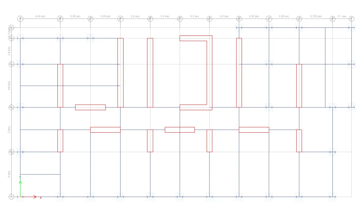
The steel beam lines are sketched in view of keeping the composite deck span within 2 to 4 meter maximum.
Also the one-way distribution symbol is marked on the floor plan which will be helpful during the slab assignment in ETABS.
(The lobby area between staircase and lift is retained as RC slab design)
Load reference from standards ;
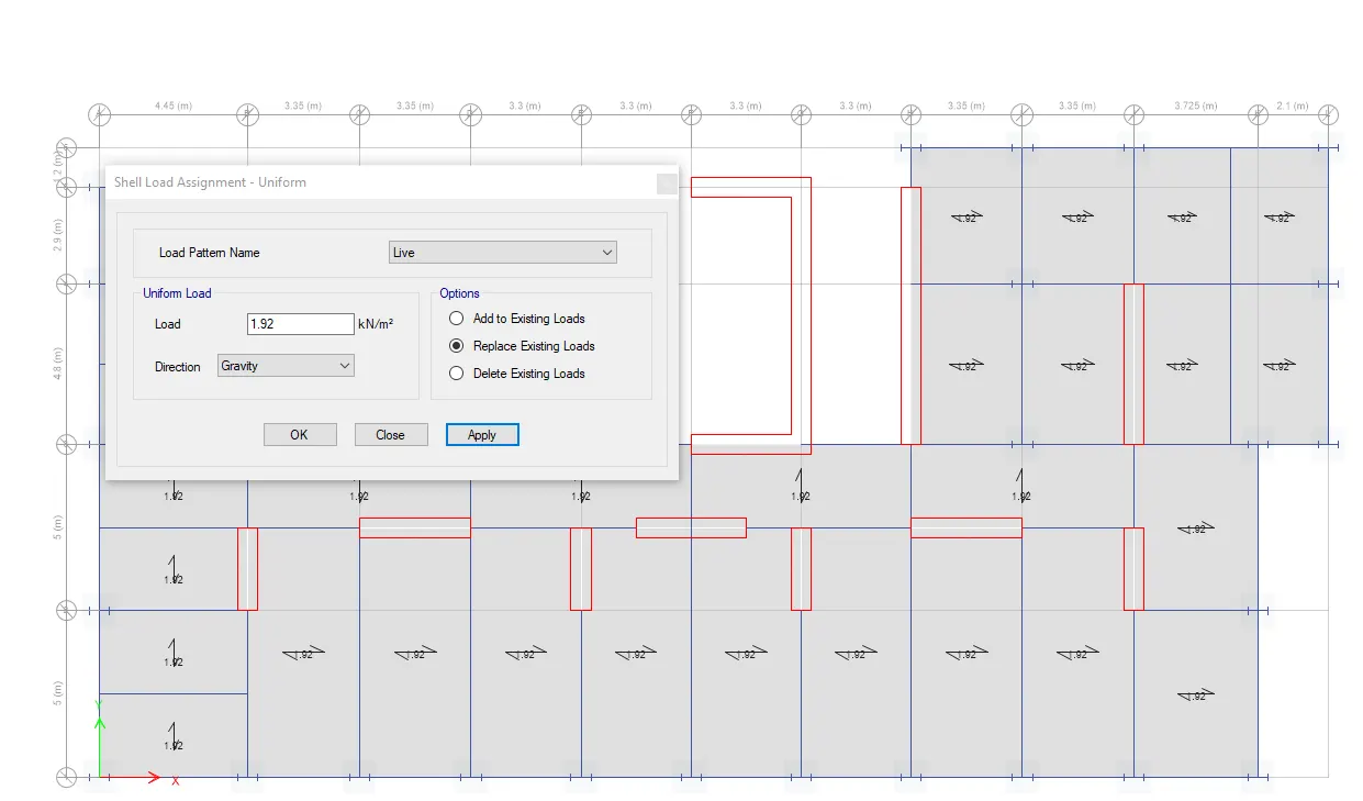
-live load american standards [ASCE -07] for residential occupancy -1.92 kn/m2
-assumed superdead load [considering floor finish , flase ceiling and service ]-2 kn/m2
-sesmic parameters from indian standard [is -1893] are as follow ,
-for apartment situated in Chennai on loose soil ,
zone -2 , importance factors -1.2 , response reductionfactors -5 .
Approximate time period of the building
For X-direction, building dimension-34.78 meter. height-103 meter. Tx = 1.57 second
For Y-direction, building dimension-17.7 meter . height-103 meter. Ty = 2.2 second
Wind parameter from Indian standard (IS-875 part 3) are as follow,
Basic wind speed - 55 m/s, category-3.
Comflor software for composite deck design:
Comflor composite deck design report is attached.
The selfweight of deck profile with concrete is 2.74 kN/m2
which is equivalent to 110mm thick RC slab.
Story assignment in ETABS:
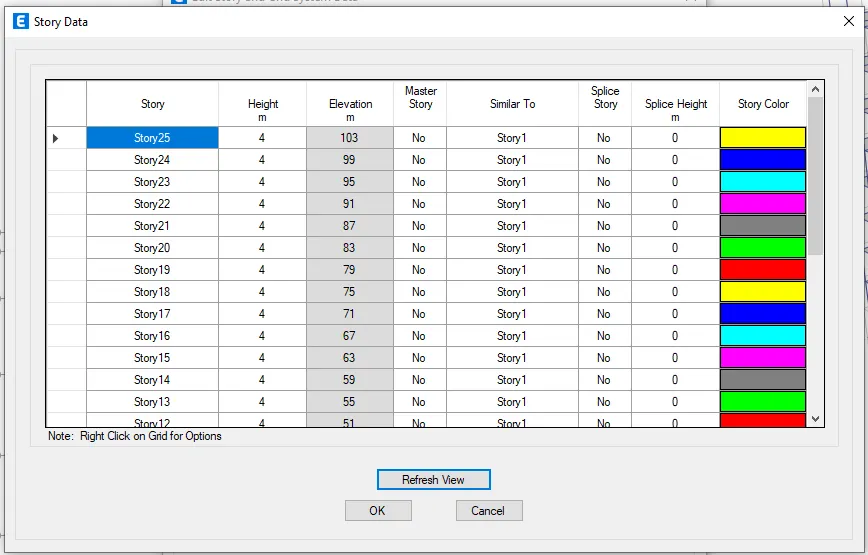
GRID ASSIGNMENT
v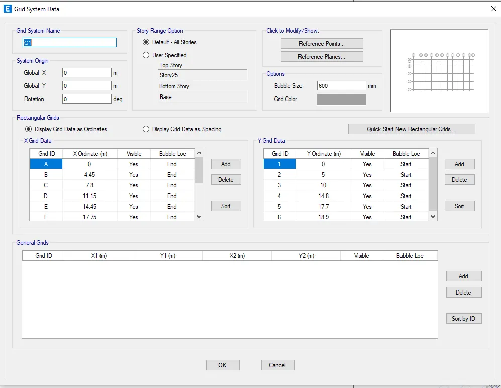
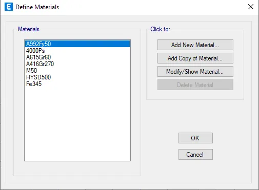
MATERIAL ASSIGNMENT [M50 CONCERETE ,FE 500 FOR REINFORCEMENT AND F 345 FOR STEEL ]
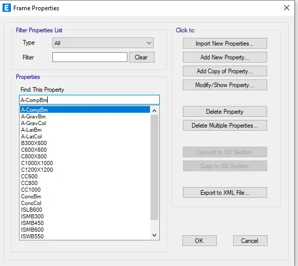
composite column ,syteel beam assignment :
slab assignment equivalent to deck thickness ;
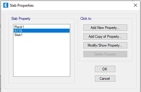
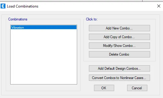
Load pattern, Load combinations & earthquake wind assignments:
Modeling of walls, composite columns & Steel beams:
Deck slab assignment:
loading assignment :
analysis and composite column design check -
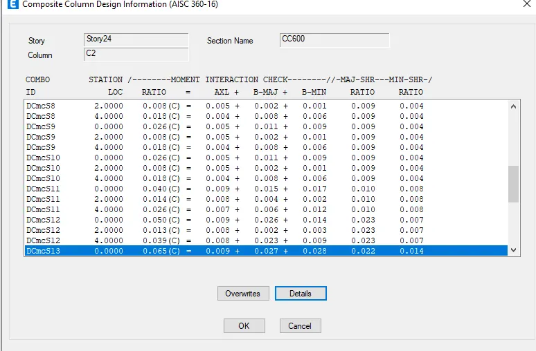
since composite column demand capacity
are less than 1 composite column section provided
in model are satisfying the requiremENT .
VIBRATION CHECK AS PER CODE
P354 ;
FRequency criteria of the composite floor
in view of walking resonance ,as follows
it is understand that ,deflection caused by 100 % dead load +10% of imposed load shall be used for determining frequency of composite floor .
and by verifying frequency of floor be greater than 3 hz , we can say the floor vibration are with in tolerance limit .
deflection of steel beam for vibration load combination is noted as 2.9 mm
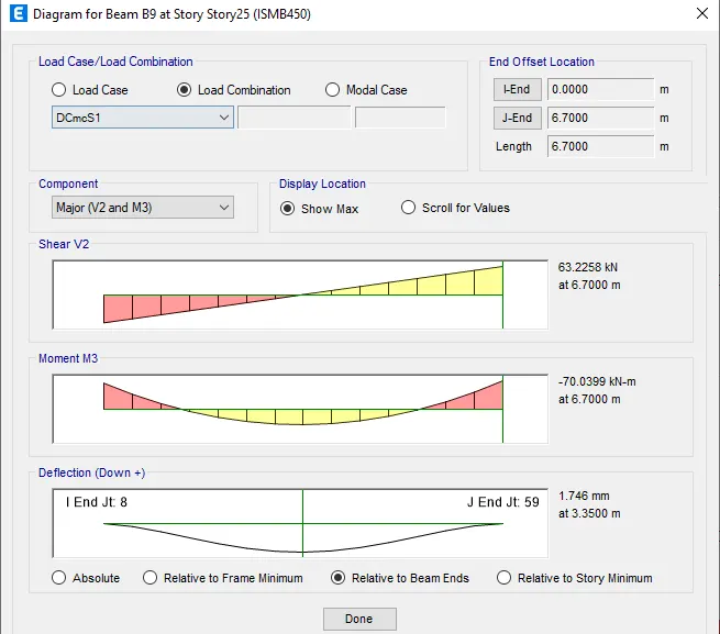
span to beam deflection ration of steel beam is =7500 /2.9 =2586 which is satisfactory .
deflection of check as per comflor report is 2.87 mm
The frequency of the floor is much greater than 3 Hz, which is beyond the walking frequency. Hence satisfied.
total deflection of floor =2.9 +2.9 =5.8 mm
so ,frequency of floor = 18/root -delta
f =7.47 hz.
frequency of floor is much greater than 3 hz ,
which is beyond walking frequency .hence satisied .
ATTACHMENT ;
COMFLOR DESIGN REPORT AND ETABS [.e2K] files are attached .