Week 7-Long Piston With Cam
Aim-
For this project, we will have to perform a transient analysis on a piston and cam mechanism model that has been provided to us. We need to run the analysis with Frictionless contact, Frictional with 0.1 and 0.2 as the frictional contact for a total of 3 cases. Find out the Equivalent Stress, Directional Deformation and Equivalent Elastic Strain and compare them for all the three cases. To give an inference as to why the results vary between cases.
Procedure-
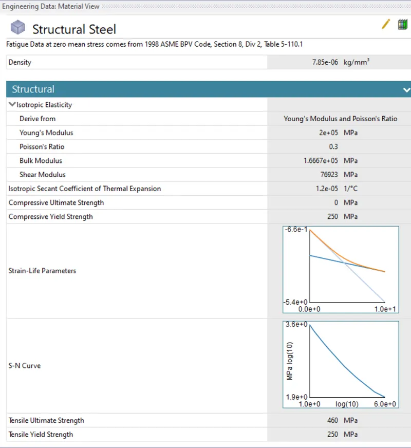
- We have to first start as new project in the ansys workbench Select transient Structural and select the proper material for the cam.
- Here no material has been specified in the project so we will select the structural steel as material.
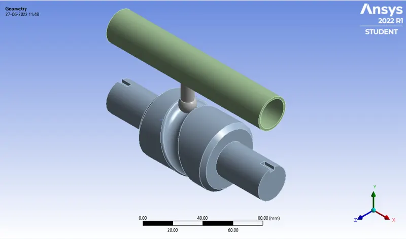
- Now we have to import the model for that right click on the geometry tab and hit import>>then select the file from saved location and hit ok.
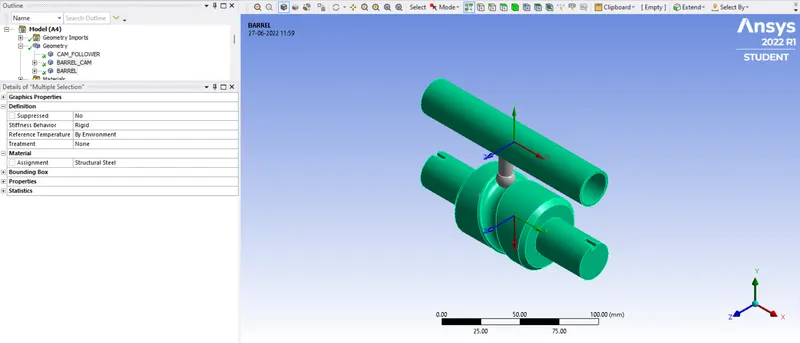
- Now we have to open mechanical model, rename the geometry model and the need to specify connections to Cam mechanism.
- Since here we are only intrested in simulation for cam only so for rest two parts we can select stiffness behaviur as rigid.
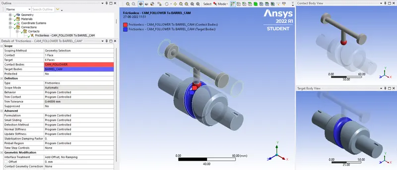
Contacts-
- Now go to contacts from drop down arrow of connections and right click on the connections rename based on definations.
- We select frictionless contact for this and for other cases we have to specify frictional contacts.
- Here for Case2 & 3 we use parametric solution method.
Case-1
Case-2
Case-3
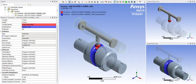
- We select frictionless contact for this and for other cases we have to specify frictional contacts.
- Here for Case2 & 3 we use parametric solution method.
Case-1
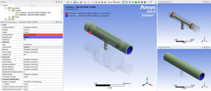
Case-2
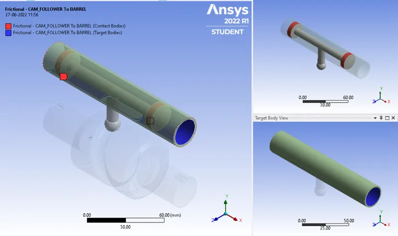
Case-3
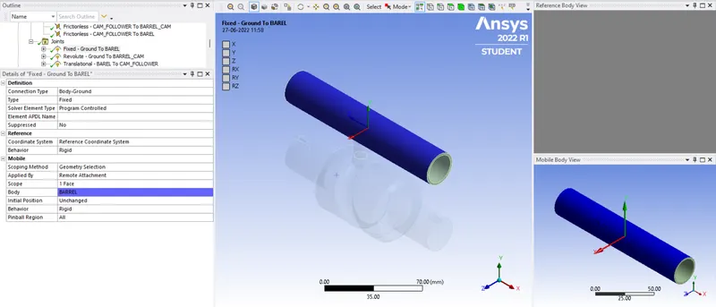
- Now we have to set the joint conection to mechanism, for that right click on connections and click on joints.
- Here for all three cases joint connection defination is same.
- First joint is fixed connection.
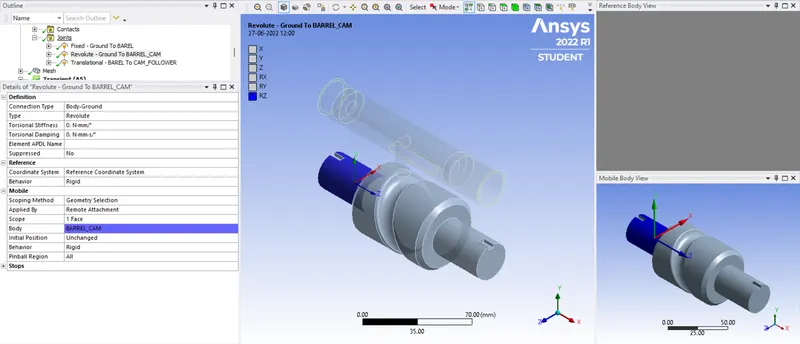
- Second is body to ground revolute joint.
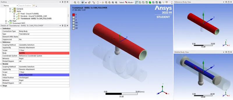
- For third connection we have to select body to body type connection with translation.
Meshing-
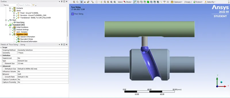
- We have to insert sizing method for mesh for cam piston head and its rotation path of barrel cam & to insert size of 3mm
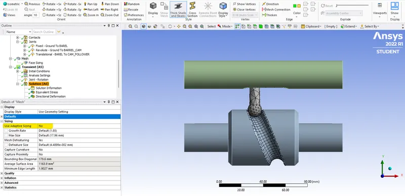
- Also in mesh in sizing put select adaptive sizing as No.
Analysis Setting-
- Here we will run stimulation for 9 time steps, refer below setting for 1st step.
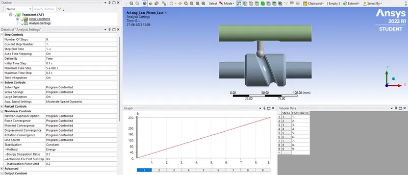
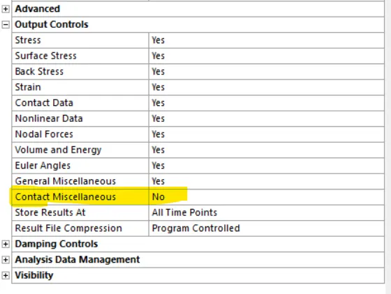
- In ouput controls keep everything yes except contact miscellaneous.
- Now for steps 2 to 9 refer below settings.
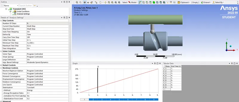
- In ouput controls keep everything yes except contact miscellaneous.
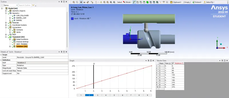
- Now we have to define a joint load for cam mechanism.
Solution Setting-
- Now for stress right click on the solution>>insert>>stresses>>equivalent (von-Mises).
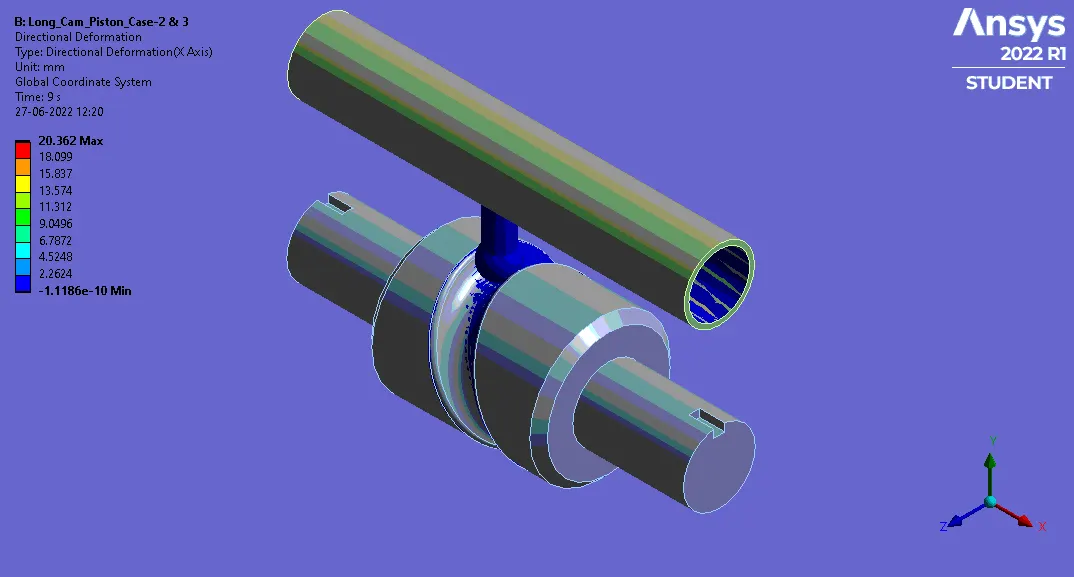
- Here we have to define directional deformation, to do so right click solution>>insert>>deformation>>directional, select X-axis.
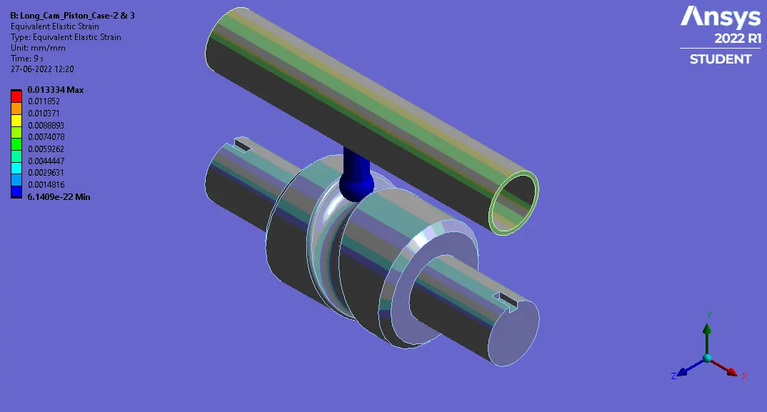
- Now for strain right click on the solution>>insert>>strain>>equivalent elastic (von-Mises).
Results-
Equivalent Stress-
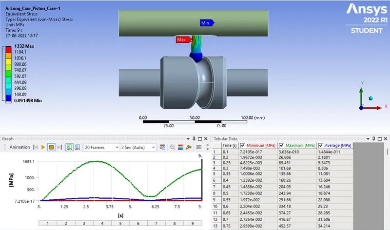
Case-1
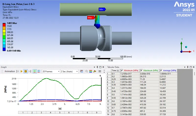
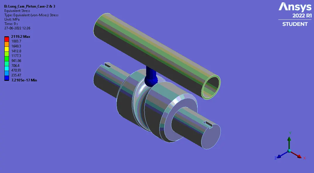
Case-2
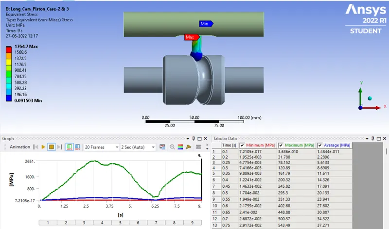
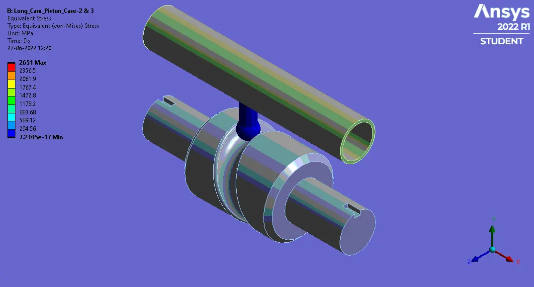
Case-3
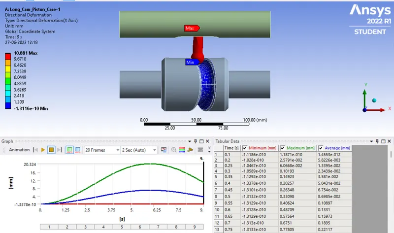
Directional Deformation Along X-axis-
Case-1
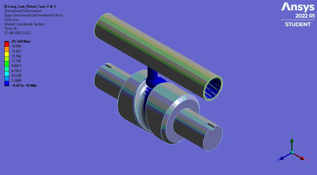
Case-2
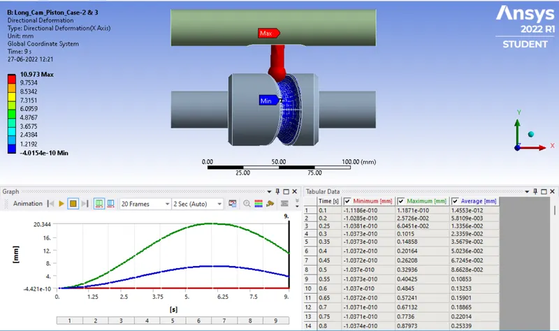
Case-3
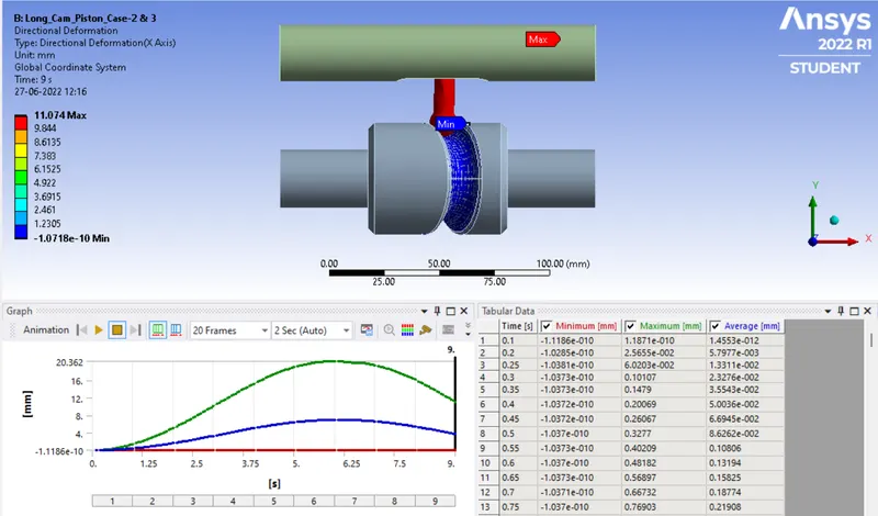
Equivalent Elastic Strain-
Case-1
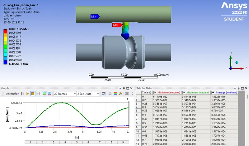
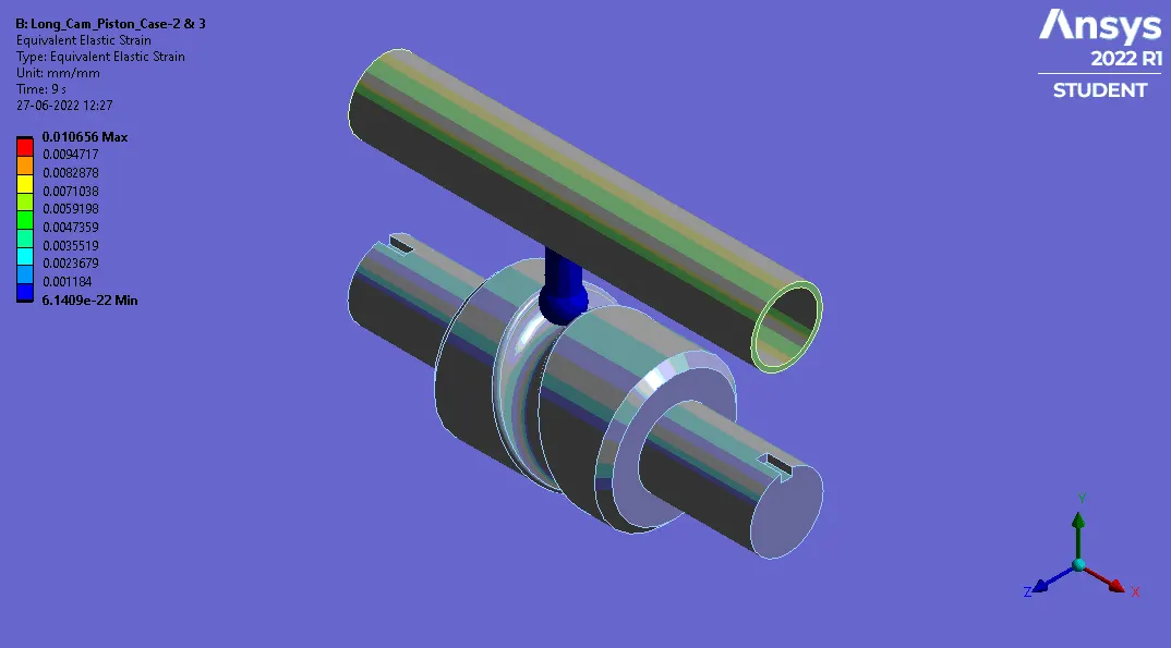
Case-2
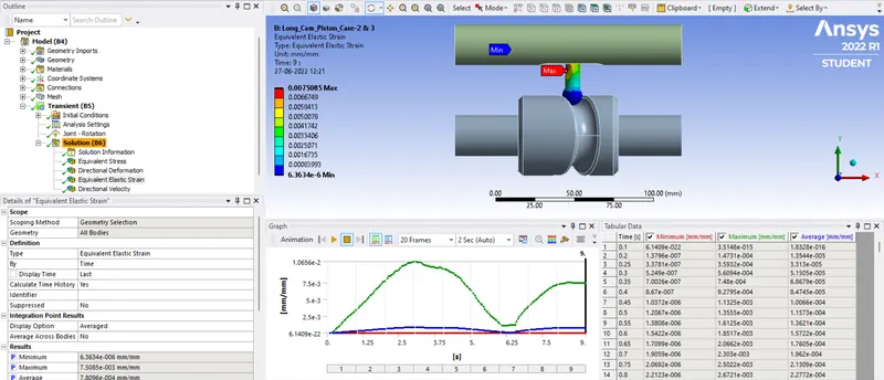
Case-3
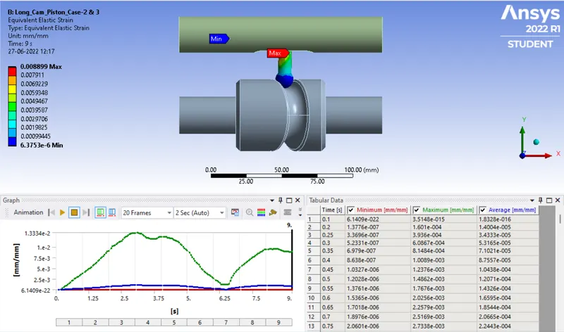
Result Comparision-
|
Case |
Equivalent Stress (MPa) |
Directional Deformation (mm) |
Equivalent Elastic Strain |
|||
|
Min. |
Max. |
Min. |
Max. |
Min. |
Max. |
|
|
Case-1 |
0.0914 |
1332 |
-10311E-10 |
10.881 |
6.409E-7 |
0.00674 |
|
Case-2 |
0.0911 |
1485 |
-4.015E-10 |
10.973 |
6.363E-7 |
0.00751 |
|
Case-3 |
0.0915 |
1764.7 |
-1.0718E-10 |
11.074 |
6.375E-7 |
0.00889 |
- From above result we can observe that the maximum stress induced on case-3 then case-2.
- In similar way deformation and elastic strains are highest for case-3.
- All the evaluated parameters are lowest for case-1.
Animated Result-
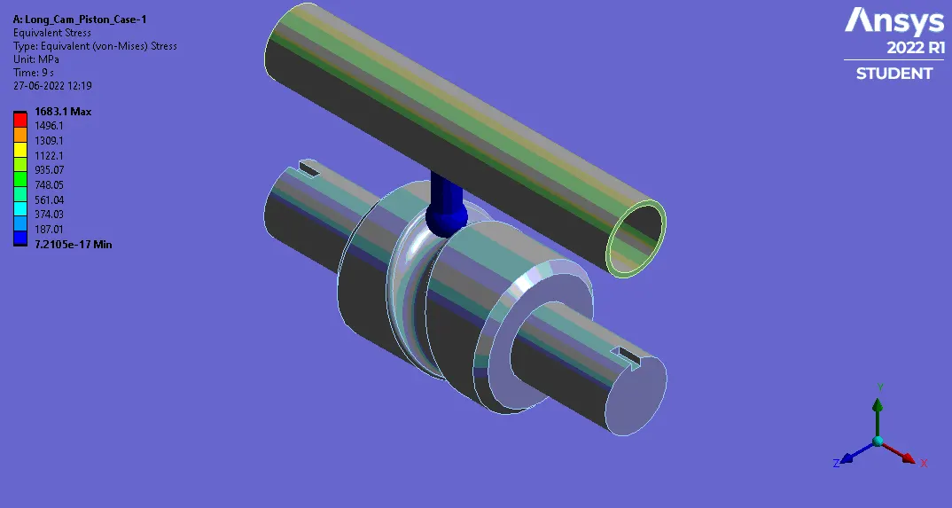
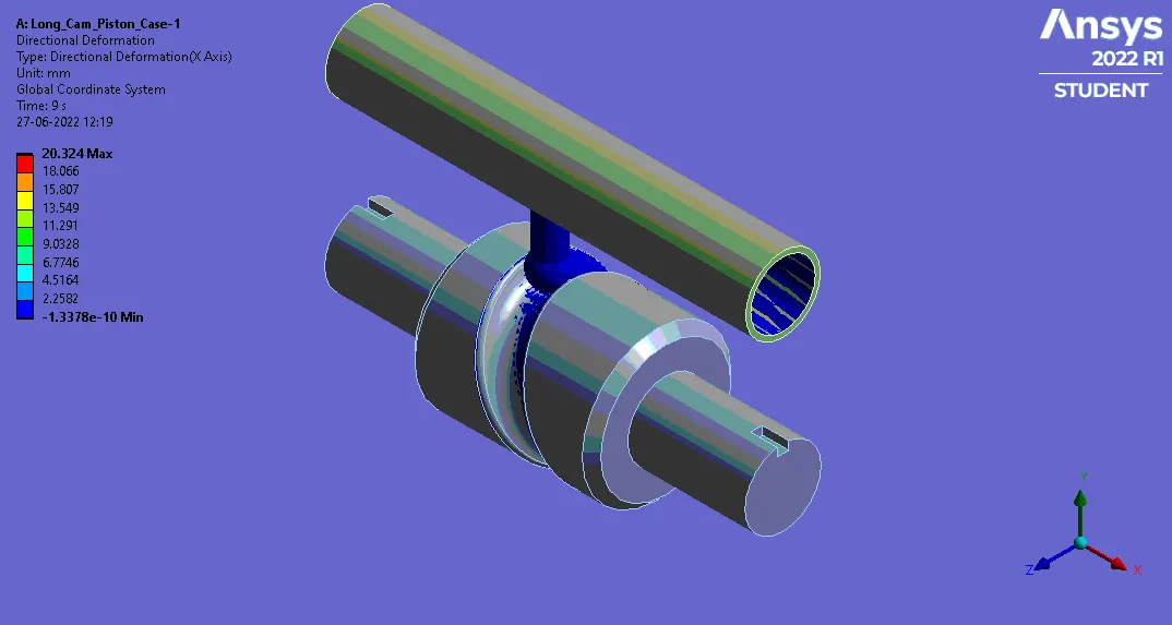
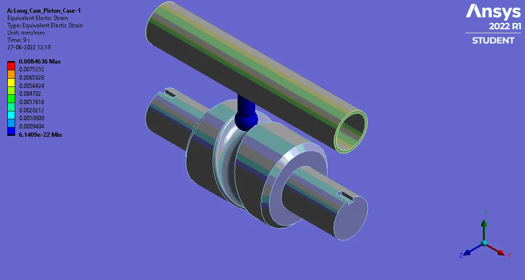
Case-1
Equivalent Stress-
Directional deformation-
Equivalent Elastic Strain-
Case-2
Equivalent Stress-
Directional deformation-
Equivalent Elastic Strain-
Case-3
Equivalent Stress-
Directional deformation-
Equivalent Elastic Strain-
Conclusion-
- From Above analysis we can conclude that as the frictional coefficient increase the stress, strain & deformation increases.
- This is due to increase in force of friction, force required to rotate the cam is also increases.