Week 6 - Creating connection for Rear door
Aim-
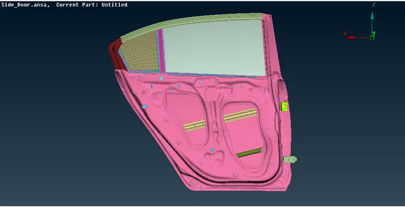
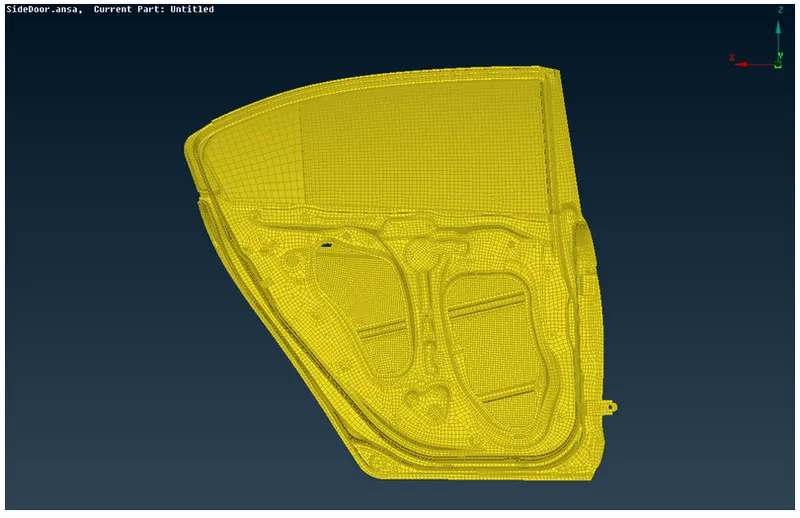
For this project for the given Rear door FE model, we have to create and Apply different PIDs for different components.
To generate the 1D connections in NASTRAN deck for diffrenet type of joint.
Procedure-
- Given model has been imported to ANSA, it has been observed that there is a Common PID present in the model.
- So, now we have to set the different PID's for every FE component.
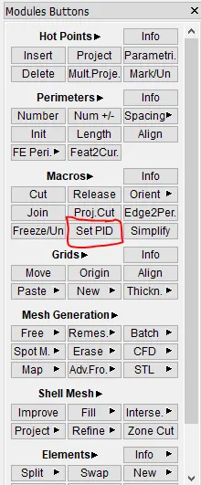
- For setting PID go to Mesh>>Macros>>Set PID>>select elements for Same and set new PID's.
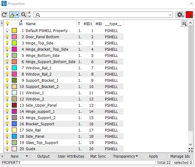
- The set PID's are as follows,
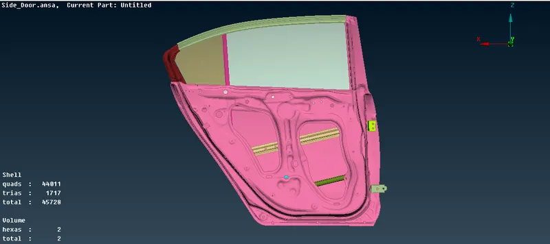
1.Bolt Joint-
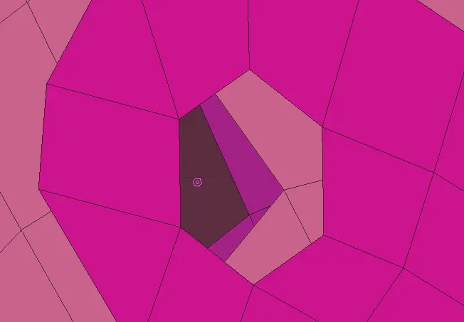
- For creating this we need a 3D centre point, for creating that go to topo>>point>>on COG>>Select By element loop and create a point there.
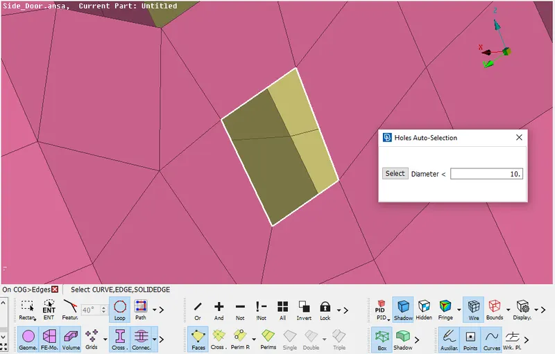
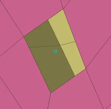
- Now go to Assembly>>convert>>3D points>>select point>>click ok>>select bolt.
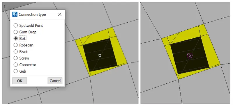
- A hexagon is created which represents bolt.
- Go to connection manager>>select the point and double click a window will appear.
- We have to select P1, P2 if there are more surfaces then select P3 & P4.
- In FE representation type select Bolt>>select apply and then Realize. a bolt connection is created.
Note- For selection P1 & P2 PID's Click on it and then click on modify then shift&F1 key and there by we can select PID required then hit enter to finalise selection.
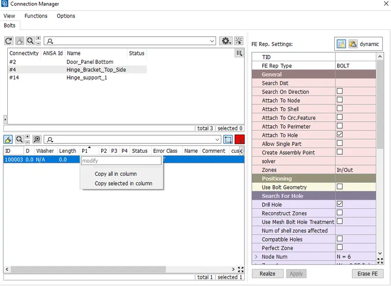
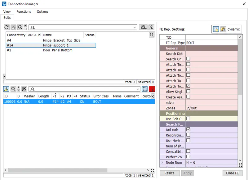
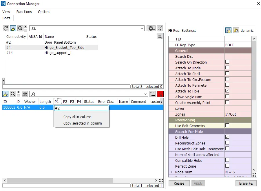
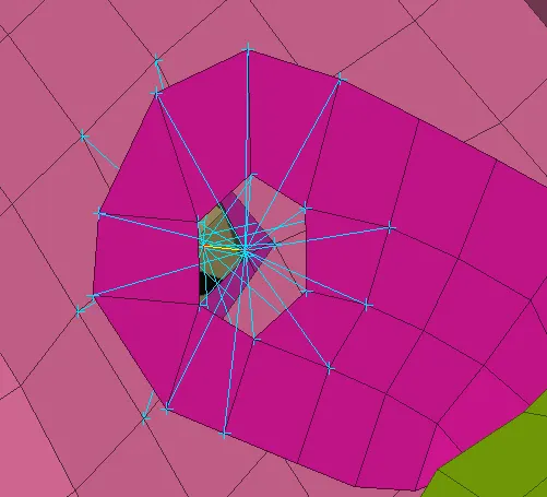
- In similar way we have to select rest of the bolt connections.
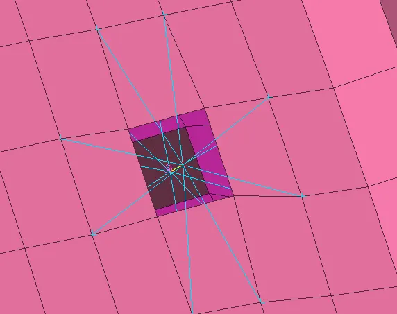
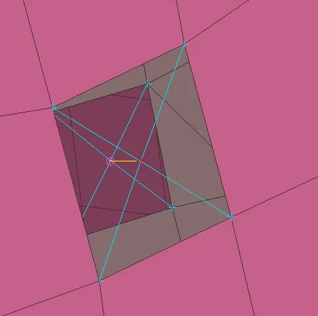
2. Hinge Support-
- For creating the hinge support we have to first create RBE2 connection, singally or by cluster.
- For that go to Nastran Deck>>Elements>>RBE2>>many nodes select nodes near hinge support region.
- Here we are going to create cluster RBE2.
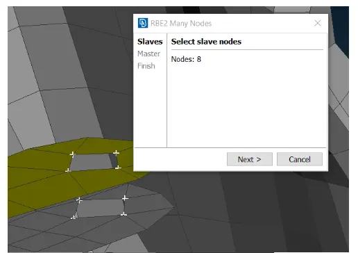
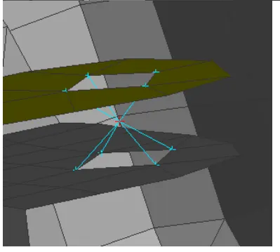
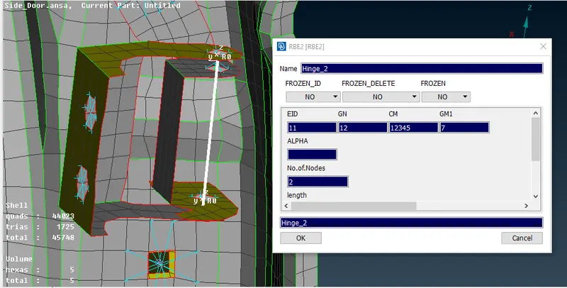
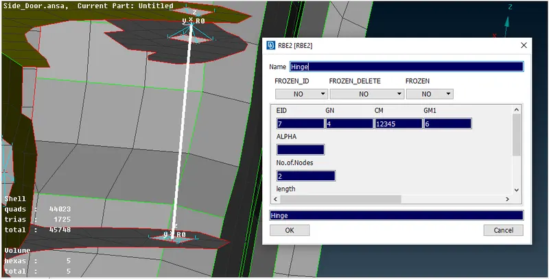
- Now we have to create the hinge joint for that we have select two nodes from RBE2.
- As it is a hinge support we have to remove rotational DOF in Z-axis as it is going to rotate in that direction.
3.Spot Weld-
- Before creating spot weld joint we have to create first the 3D point near joint for that go to topo>>points>>on COG>>select faces and it will be created.
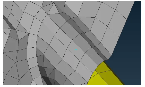
- Now go to assembly>>convert>>3D points>>select the point>>click on>>spot weld point.
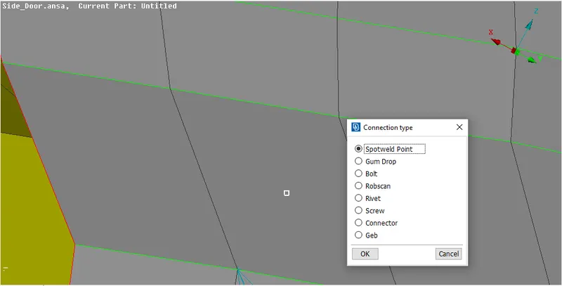
- Now a spot weld Shape has been created.
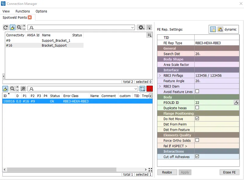
- To create Spot weld joint joint go to connection manager select spot weld joint and a new window will appear, select P1, P2 and FE representation type as RBE3-HEXA-RBE3.
- Search distance as 20 and create PSolid ID, for that click shift&? button at once ant it will take to properties menu there we have to create Psolid propert and assign the same with double left mouse click.
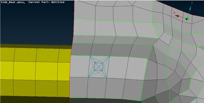
- Click on apply then realise and Spot weld joint will be created.
5. Door Handle-
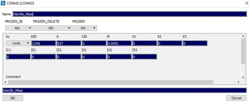
- Since there is no actual handle but for actual analysis there will handle of 100gm which will act here as a load, so we have to create CONMass here between centre of handle holes.
- Before that we have to create RBE2 links and then with two node RBE2 link we have to create centre node where we will deploy mass.
- For creating RBE2 links Go to Nastran>>Elements>>RBE2>>many nodes and select nodes of door handle cutout.
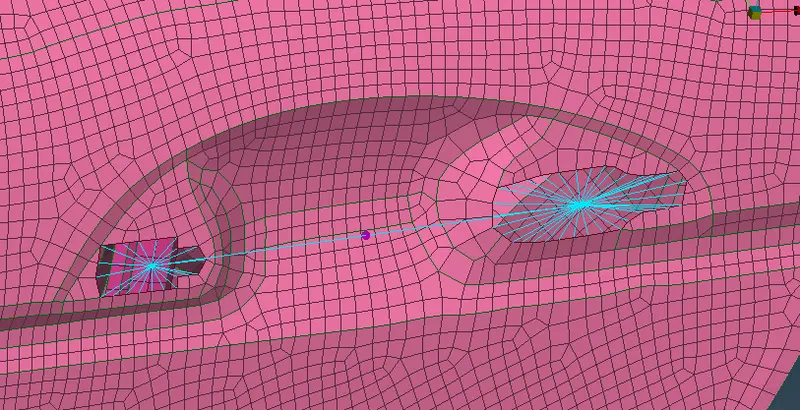
- For creating mass go to Nastran>>elements>>CONMi>>CONM2>>select Centre node and mass to it.
6. C-bush Connection-
- In Car door close to window there is a weather strip attached to it which in CAE considered as C-bush connection.
- Before that we need a Curves for that so to create curves go to Mesh>>perimeters>>Feature to curve>>select window class outer areas.
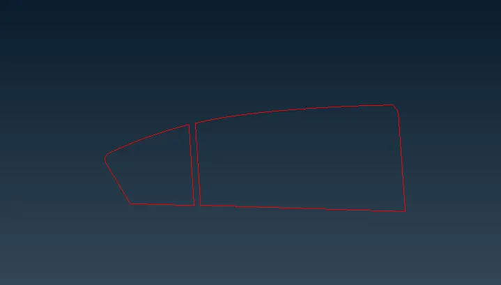
- Go to Convert>>Curves>>Spot line then ok.
- Go to connection manager>>select curves>>one by one and select P1 & P2 Accordingly then set spacing as 10 and in FE representation type RBE3-CBUSH-RBE3.
- Give search diatance as 50 and select & Create P-bush ID.
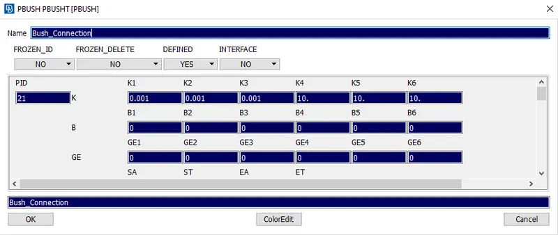
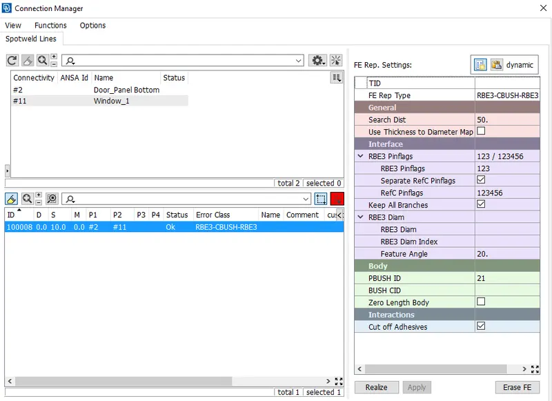
- Click on apply and then realise it will create the C-bush connection.
- Similar way we have to create connection for all remaining curves.
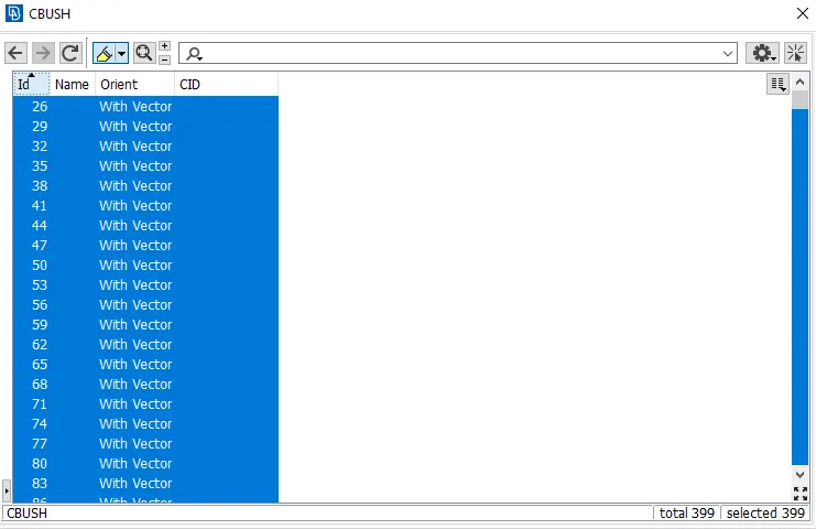
- Since all the C-bush connections have taken all the vector direction diffrently so we have to set all the connection direction to our main Co-ordinate system.
- fo that go to data base>click on drpo down of elements select C-bush over there and double click.
- new window will appear there change the view mode by clicking on show/hide columns and then search Orient and We will see that all nodes have diffrenet Vector setting.
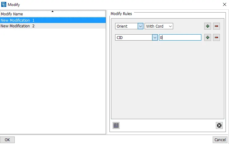
- To set all the connection to same select all elements and right click>>select modify>>new window will appear, create new modification window and in first one select orient and on CID and give value as 0 then click ok.
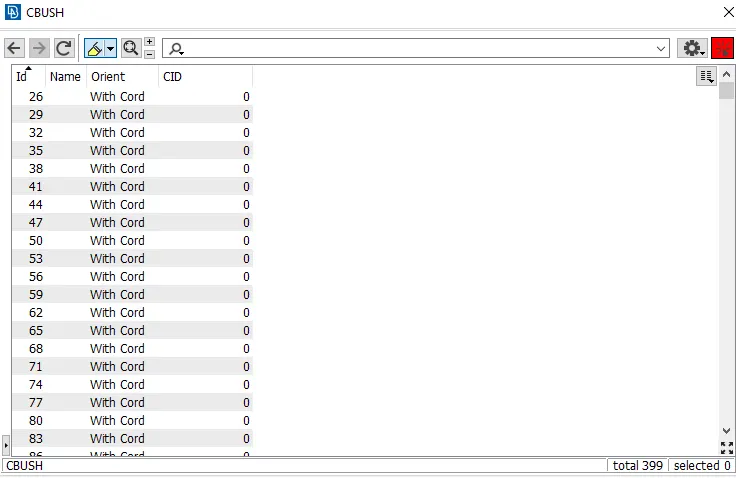
- All the connections have been revised to single cordinate system.
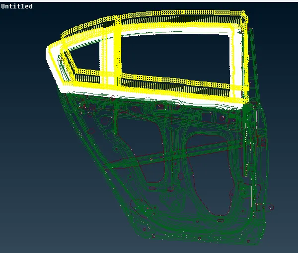
7. Seam weld-
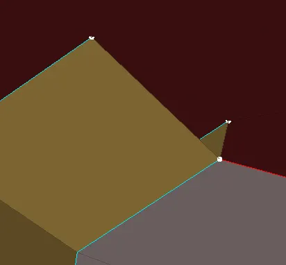
- Initially we have to create curves for that go to Mesh>>perimeters>>Feature to curve>>select window class outer areas.
- Go to Convert>>Curves>>Seam line then ok.
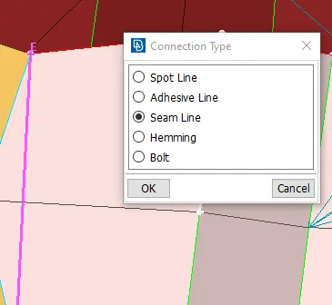
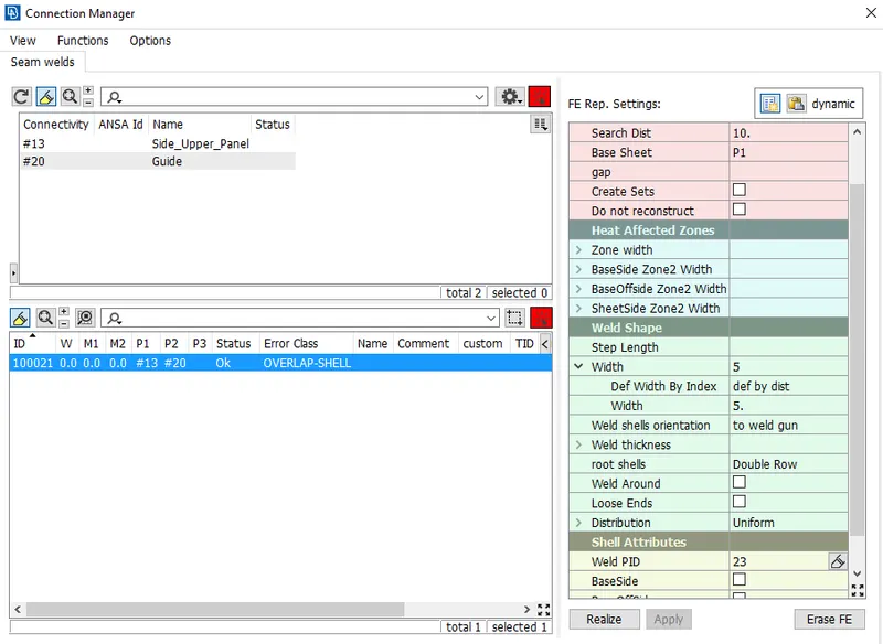
- Now go to connection manager and select the curve select P1 & P2 and for FE connection type select Overlap-sheel (Since both parts are parallel).
- Put search distance as 10 and width as 5 since element size was 5., set Weld PID and click apply and realise.
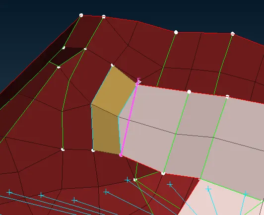
- Now our weld joint has been created.
Learning Outcome-
- Learnt about how to create different property to each element type.
- Studied and applied various connections like bolts, spot weld, seam weld, hinge joint.
- Learnt about how to create mass and Cluster Element connections in RBE2.
Conclusion-
We have successfully creaeted different properties and deployed required connection to proper places like bolts, hinges, spot weld, seam weld bush connection. There by satisfying all the criteria mentioned in this project discription.