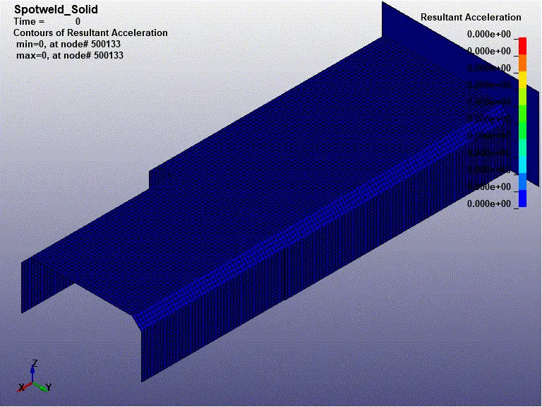
Week - 5 - Modelling Spotwelds
Aim-
to run a crash box simulation using beam spotweld and solid hex spotweld and to compare the results for both type of spotwelds.
Objectives-
- Input. k file and output files (D3PLOT, GLSTAT, SLEOUT, RCFORC)
- Animation of the final simulation
- Cross-sectional force generated in the middle of
- Acceleration plot of a node in the middle
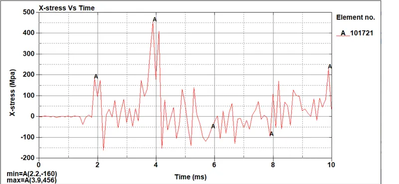
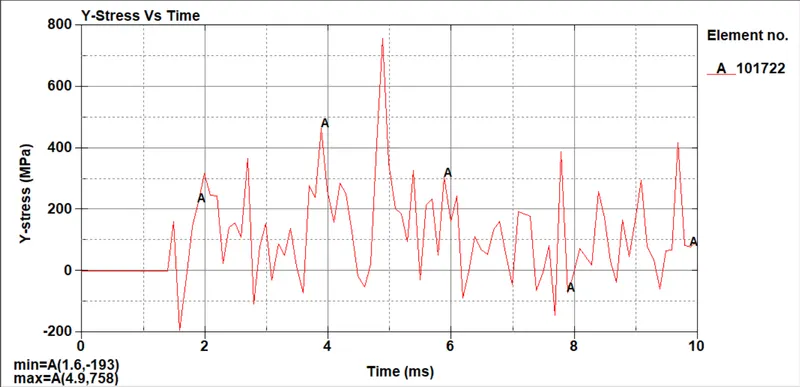
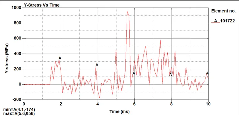
- Maximum directional stress along the length (X stress, Y stress etc.)
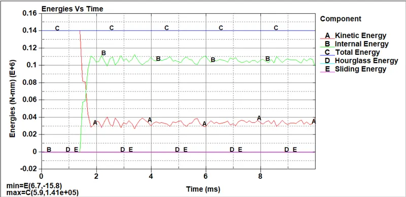
- Plot of all energies (total, internal, kinetic, hourglass, sliding)
- Compare the accelerations and stress/strain plots.
- Also to see failure criteria in shear and normal cases.
Procedure-..
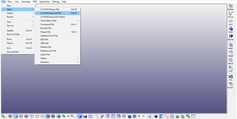
- We have to open the given LS-Dyna keyword (.k file) file in LS-PrePost, using option File>Open>LS-Dyna Keyword File as shown in below snap.
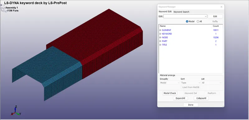
- Now as we can see from above snap that the model has no input so we have to give the inputs now.
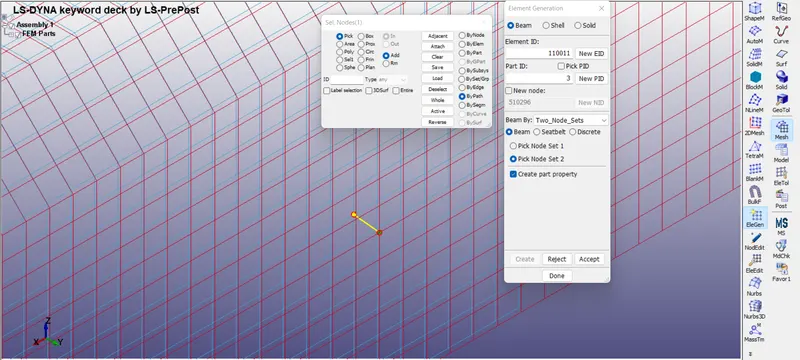
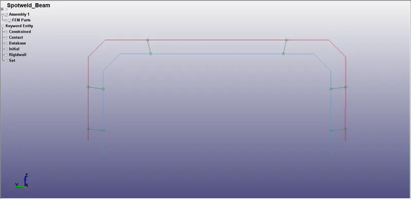
- Firstly we have to create the spotwelds for the two section to join them, for that go to mesh>>element creation>>create>>beam and select the nodes from both elements>>by two node set.
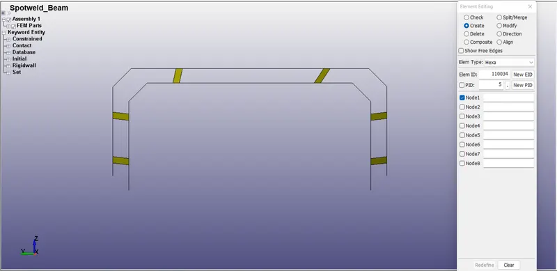
- Now to create solid spotweld joint go to Element Tools > Solid > select the six nodes for hex element creation.
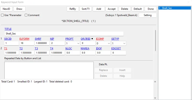
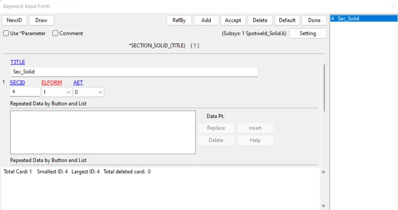
- First we will start with section card, to create section card from keyword>>all>>section>>shell>>here we will input id, elform type and thickness as shown below,
Note- Here Automatically the section and material card will be created for beam which we need to delete before creating new section and material cards.
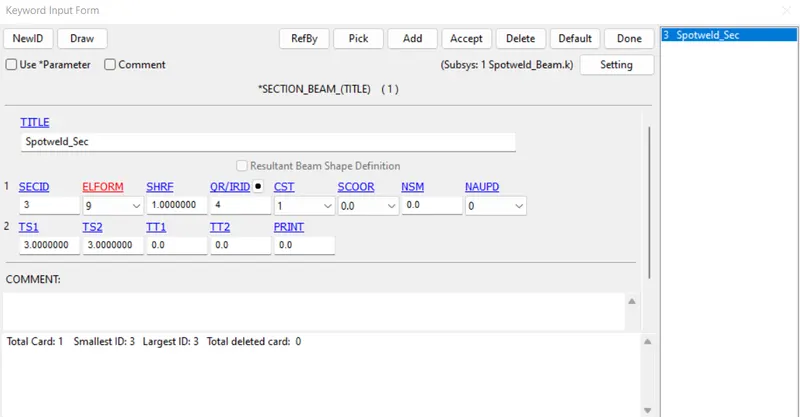
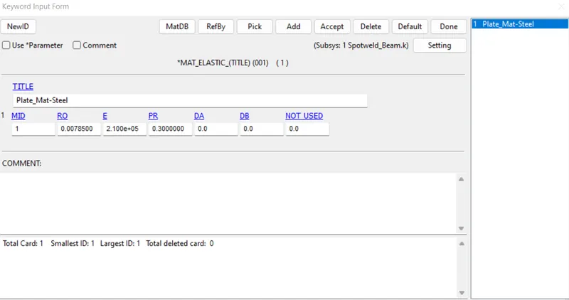
- Now assign material Properties to the beam & solid elements > Keyword MAT SPOTWELD 100 and enter material properties, methods to fail the weld, also create material properties to the sheetmetals as 001-Elastic.
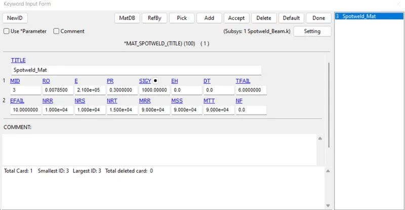
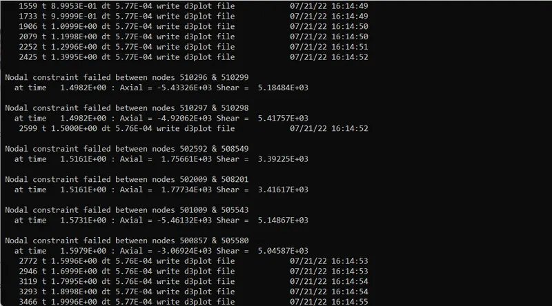
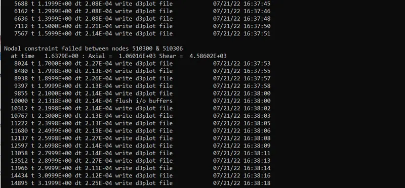
- Here we wanted the spotwelds to fail at 6ms so have inputed the value as 6ms in TFAIL.
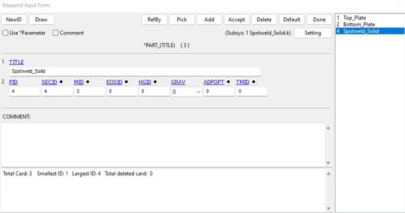
- Now we have to assign above created properties to part id.
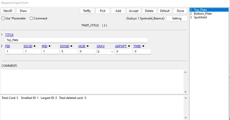
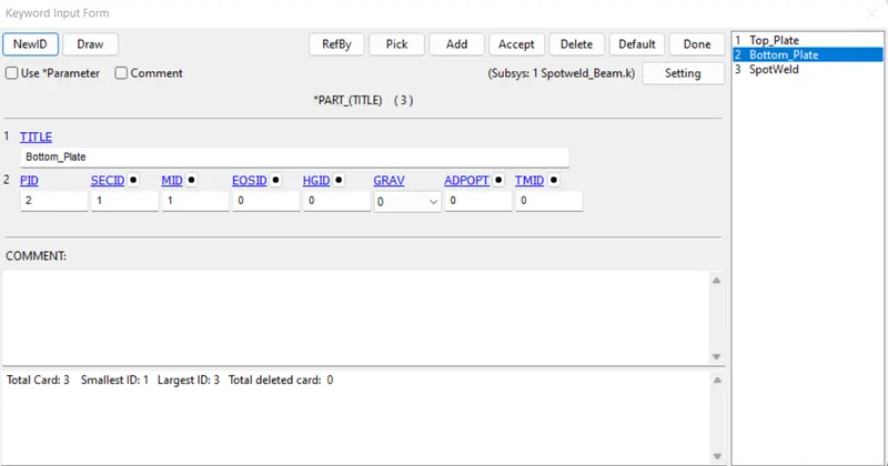
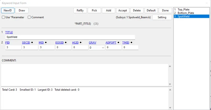
- Part properties for solid element is as follows,
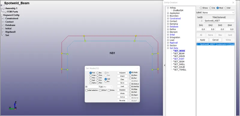
- Here we have to select the nodes of all beams and solids and all shell elements so we need to create nodes set and shell set. For that go to create entity>>set data>>set node>>select nodes and apply then done.
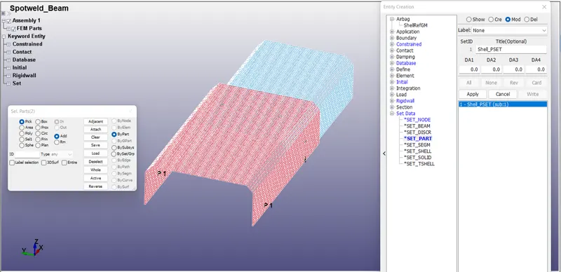
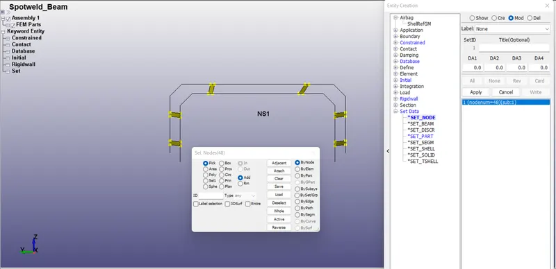
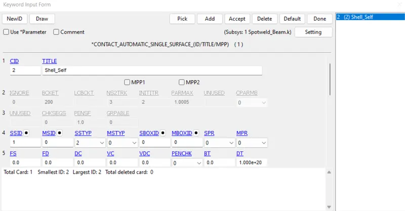
- Now we have to create the contact for the for the box, AUTOMATIC_SINGLE_SURFACE contact, consedring it as frictionless, here we have only select the slave nodes no master is going to be present.
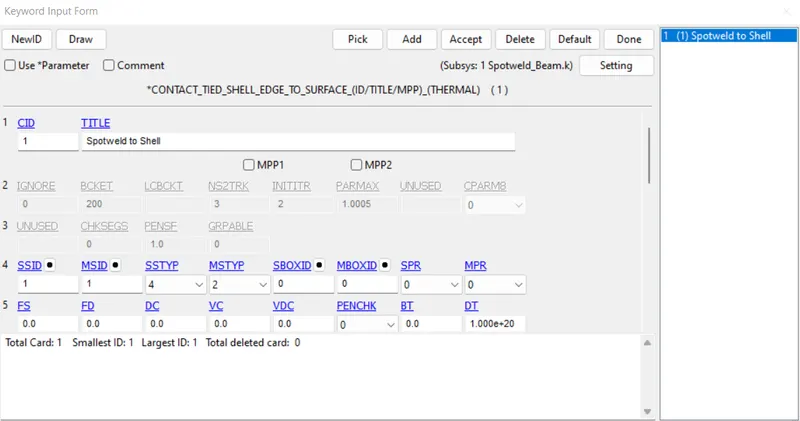
- Now we have to create the contact for the for the box, CONTACT_TIED_SHELL_EDGE_TO_SURFACE contact,
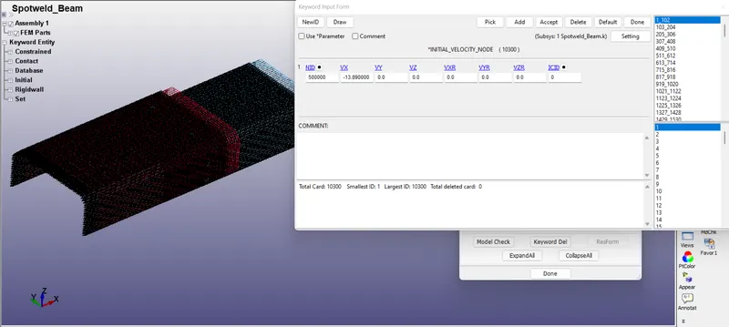
- Now we will create the boundary conditions for crash box for intial velocity as 50kmph which is equal to 13.89mm/ms.
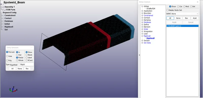
- Rigid walls mimic surfaces or volumes that are frequently used to represent stiffer structures that are either stationary or in motion.
- A stationary planar rigid wall is created ahead of the frontal portion of the spotweld box by selecting a node on the edge, Select planar option and Geo-Vector >> 1n+NL
- Now translate the rigid wall to some distance in the direction of the velocity of boxes with spotweld.
- The rigid wall is created at a distance of 20mm away from the boxes.
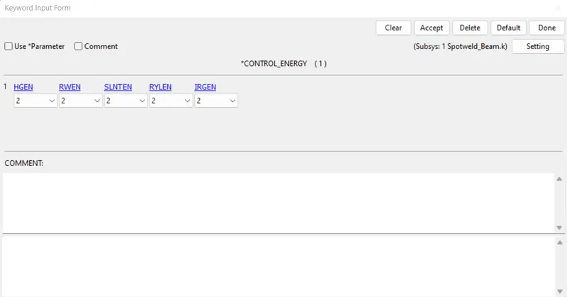
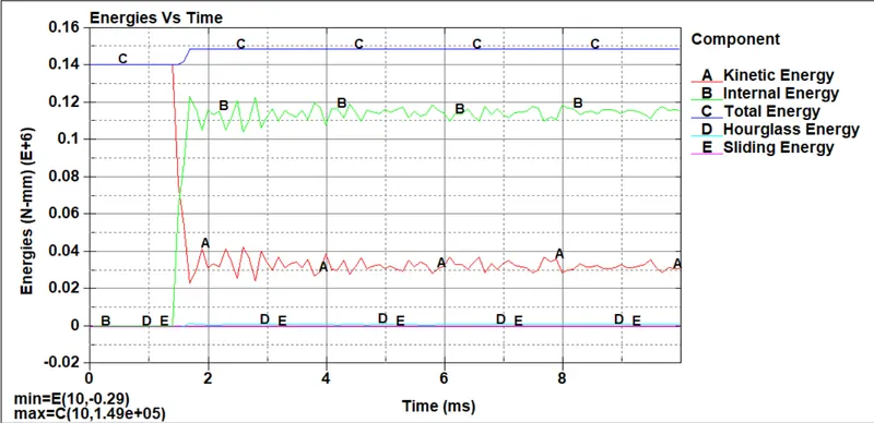
- Now we will define CONTROL_ENERGY card for energy dissipation as shown below.
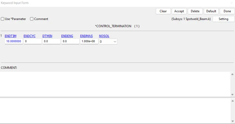
- Finally we will define the termination time of the simulation which is necessary to run the simulation. The termination time is given as 10ms in CONTROL SIMULATION Keyword as shown below.
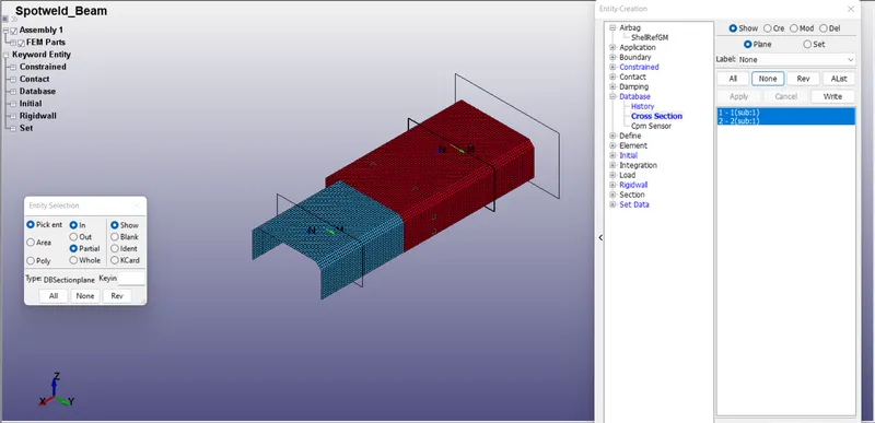
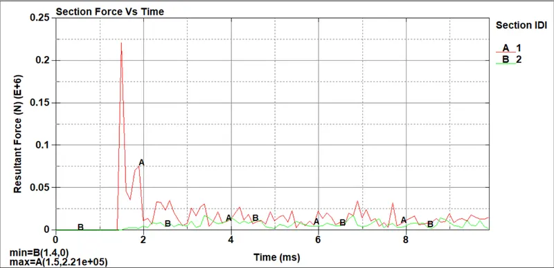
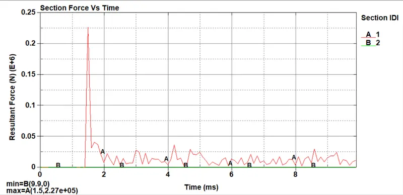
- Now we have to create section for getting section for getting cross sectional forces.
- Cross-section can be created under DATA BASE keyword to measure all cross sectional forces.
- Usually, two rows of elements are selected as a section or a simple plane creation can also be done.
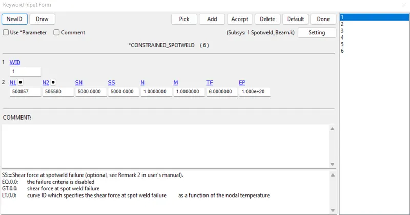
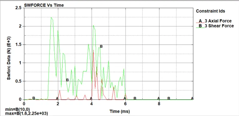
- Now we will define the contrained spotweld to check whether the shear force and normal forces fails.
- Depending upon number of welds we have to create the Contrains, here it is six.
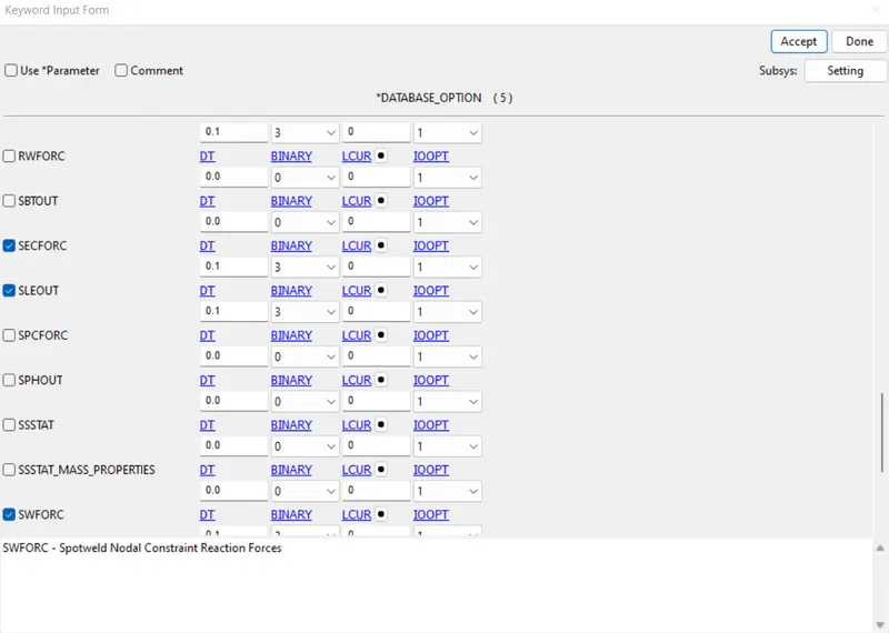
- Now the requested outputs are d3plot, history node and ASCII options are
- GLSTAT: Global Data
- SLEOUT: Sliding Interface Energies
- RCFORC: Resultant Interface Forces
- SECFORC: Cross Section Forces data
- SWFORC: Spotweld Nodal Constraint Reaction Forces
- Now we have to check the model from model checker.
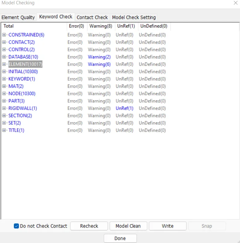
- Since there is no error we can proceed further to save and run the keyword file.
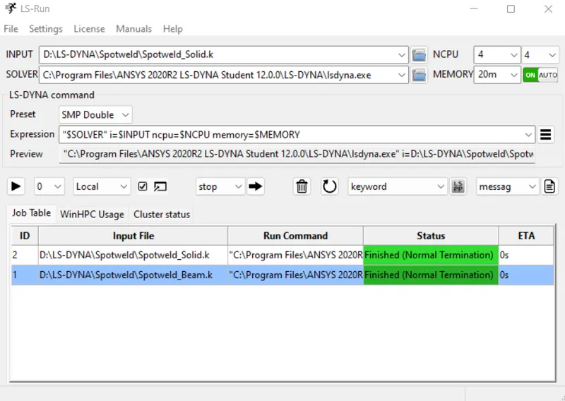
- Both simulations ended with Normal Termination. Therefore, all the models are simulated successfully.
- Now we can open this files one by one using LS-post processor.
Results & Plots-
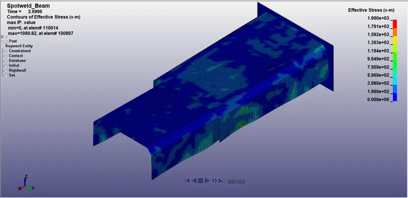
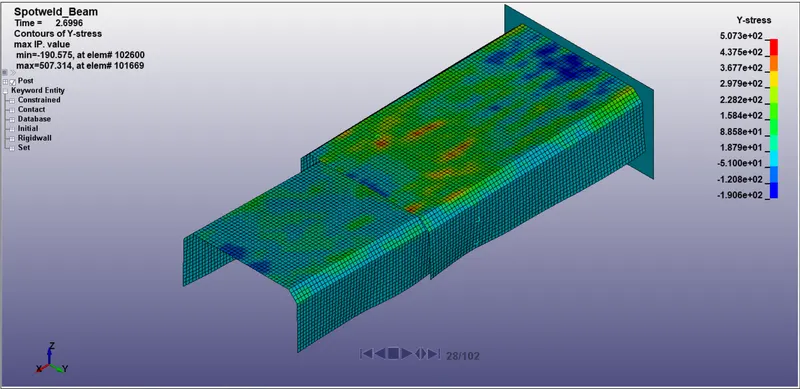
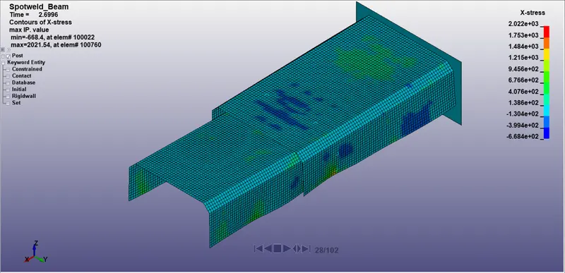
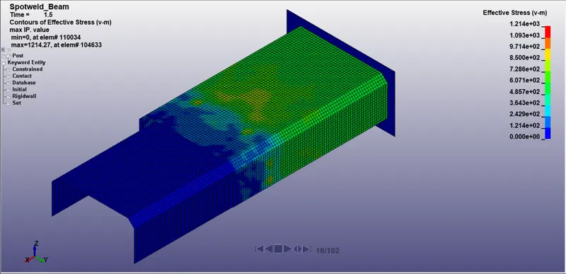
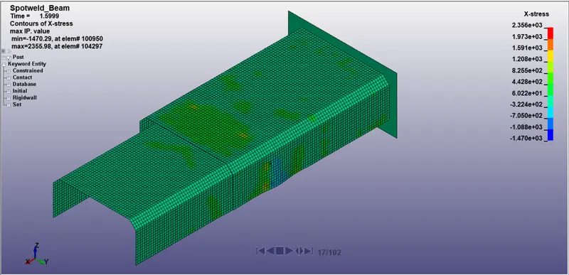
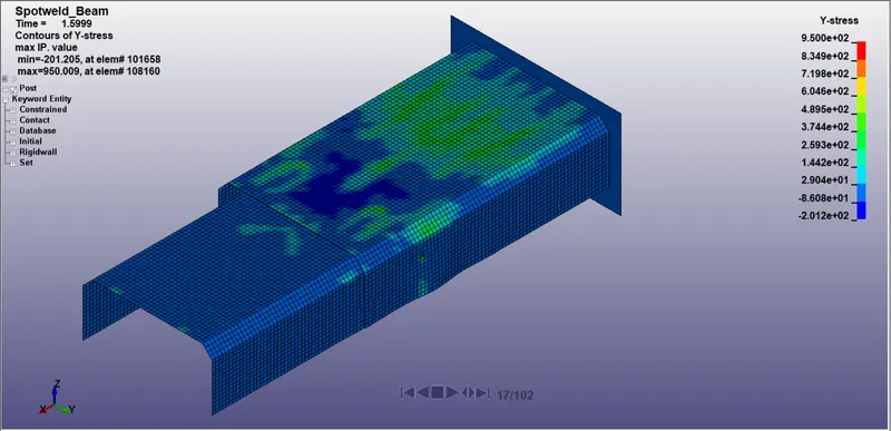
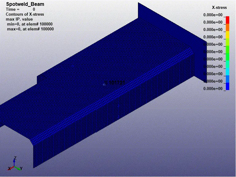
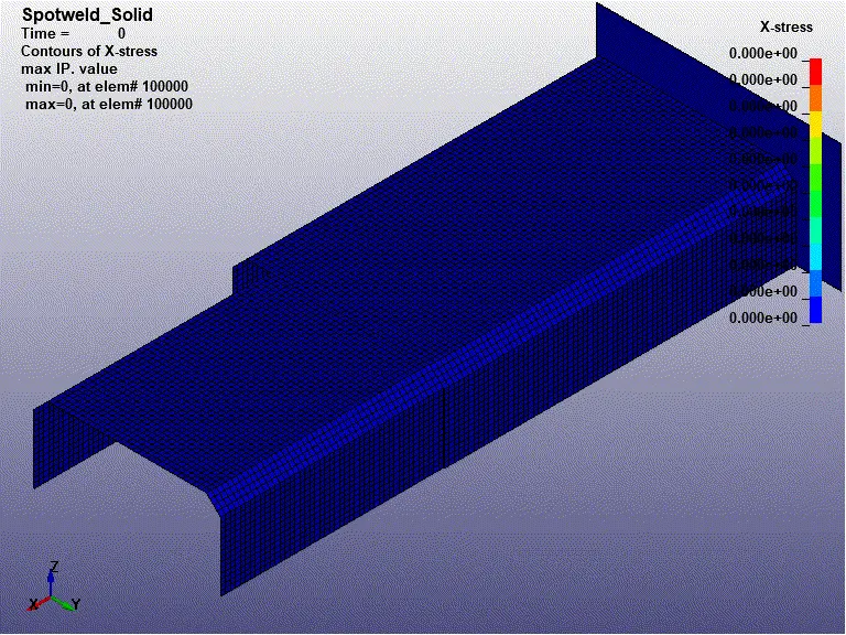
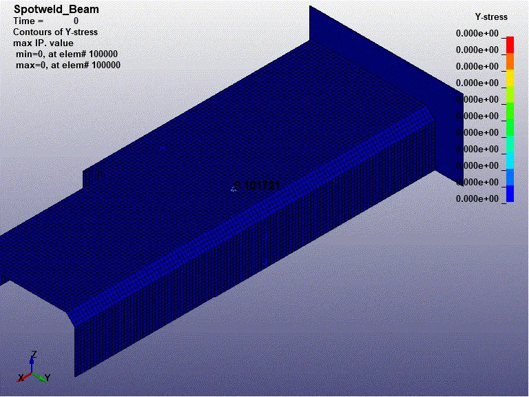
Stresses-Effective Stress (V-M), X-stress, Y-stress-
Beam Spotweld-
Solid Spotweld-
Resultant Sectional Force-
Beam Spotweld-
Solid Spotweld-
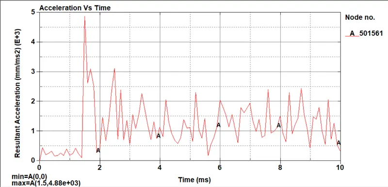
Acceleration plot of a node in the middle of the crashbox (along its length)-
Beam Spotweld-
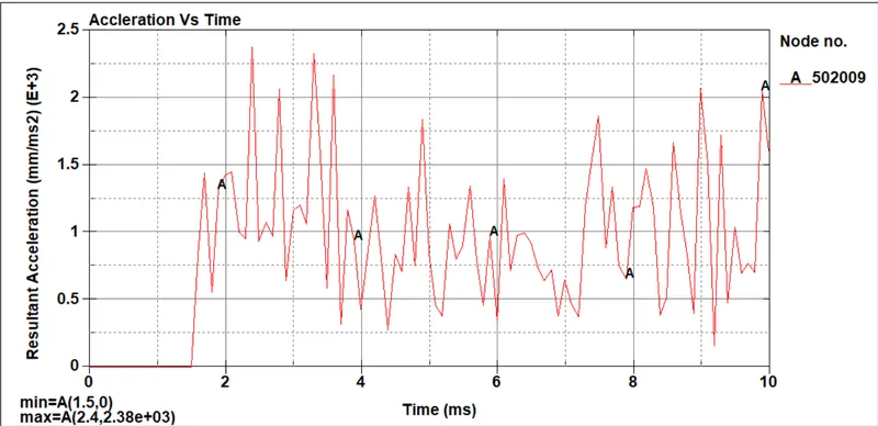
Solid Spotweld-
Maximum directional stress and strain along the length
X-stress-
Beam Spotweld-
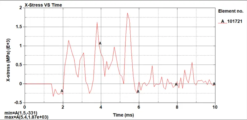
Solid Spotweld-
Y-stress-
Beam Spotweld-
Solid Spotweld-
Plot of all energies (total, internal, kinetic, hourglass, sliding)-
Beam Element-
Solid Spotweld-
Force Failure-
Beam Spotweld
Solid Spotweld-
Shear Force & Axial Force Vs Time-
Beam Element-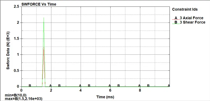
Solid Spotweld-
Conclusion-
- We can conclude that in order to get robust contact, solid elements are needed to represent the weld.
- Also Hex elements provide significantly improved performance over a beam element.
- When we have no accurate or standard data for the Axial & Shear forces at failure, than we can use the Time dependent failure to get the results at which the Spotwelds are failing, and for that we have to run the simulation for more longer time dependent failure or we can also use plastic strain failure also.
- From overall results, we can conclude that Solid elements are more robust and can give more accurate results and are more preferable. Though in some cases, where only axial forces are more important, or for more faster results, Beam elements can be used.
Animations-
X-Stress
Beam
Solid-
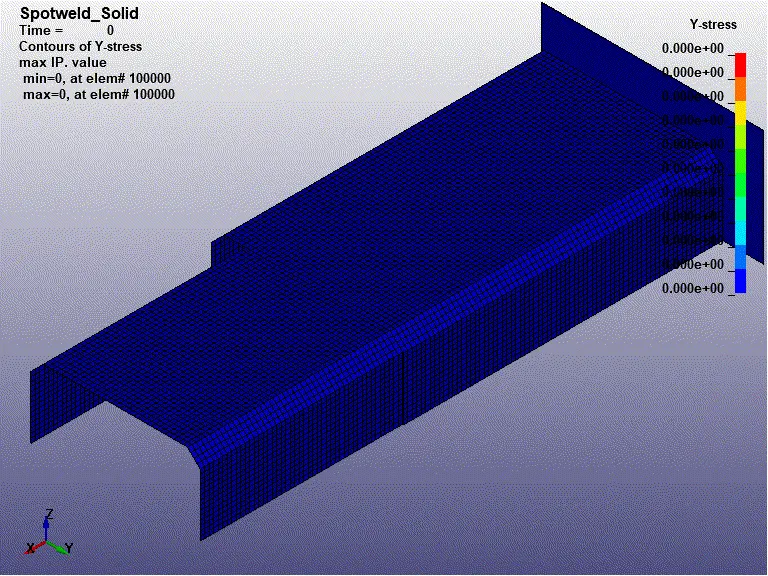
Y-Stress-
Beam-
Solid-
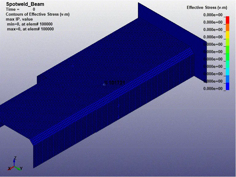
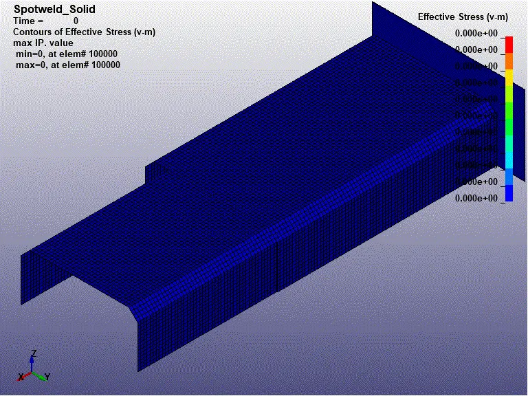
Effective Stress (V-M)-
Beam-
Solid-
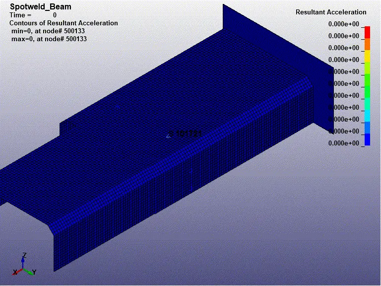
Acceleration-
Beam-
Solid-