Week 5 Bending of iPhone
Aim-
We have to perform structural analysis for Iphone bending & is to be performed for 2 different cases. Variation of certain settings is also to be performed and conclusions are to be added to the report.
Objective-
simulate the bending of iPhone as per the given cases below
Case 1: Simulate the model as it is given in the video
Case 2: Move the bottom fingers from their defined position to the given position X= 22.5mm & Z= 10mm and obtain the results for the simulation. Also define the S-N curve for the Aluminium Alloy material as per values given below and determine the fatigue life results for the same.
| Stress, MPa | Number of Cycles, N |
| 225 | 10000 |
| 175 | 100000 |
| 143 | 1000000 |
| 110 | 10000000 |
| 80 | 100000000 |
Results and Deliverables
- Obtain the directional deformation for the model
- Factor of Aluminium Alloy NL
- Life of the Aluminium alloy for the case
- Compare the results and present with the conclusion.
Procedure-
- We have to first start as new project in the ansys workbench and select the proper material for the Iphone and fingers.
- Here material has been specified in the project so we will select materials as stated.
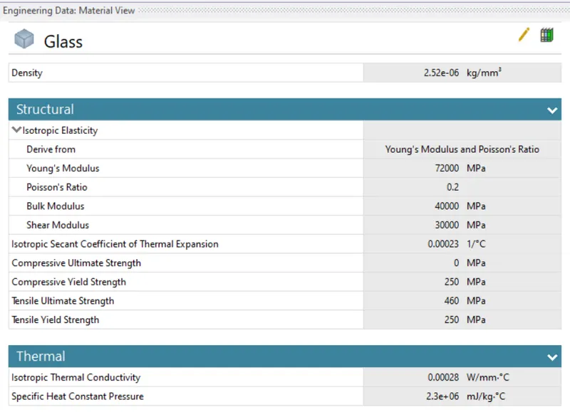
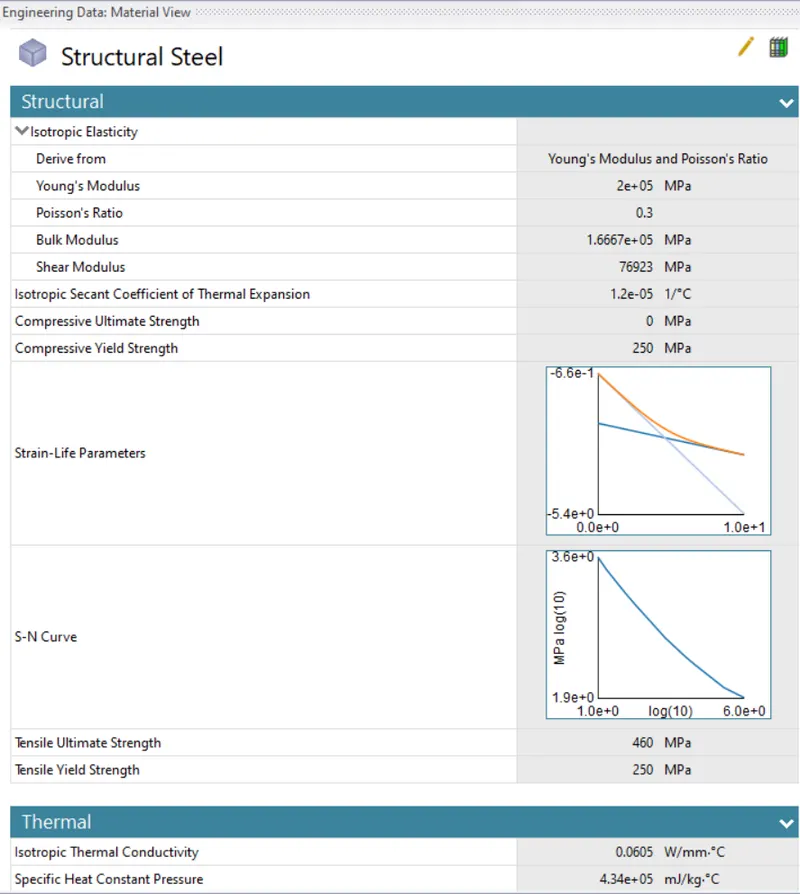
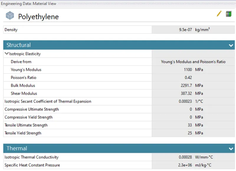
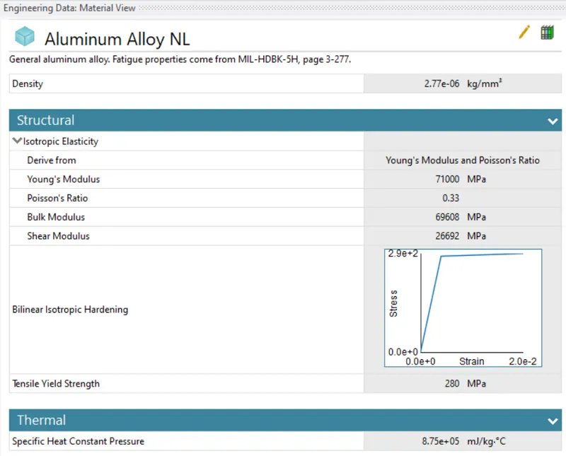
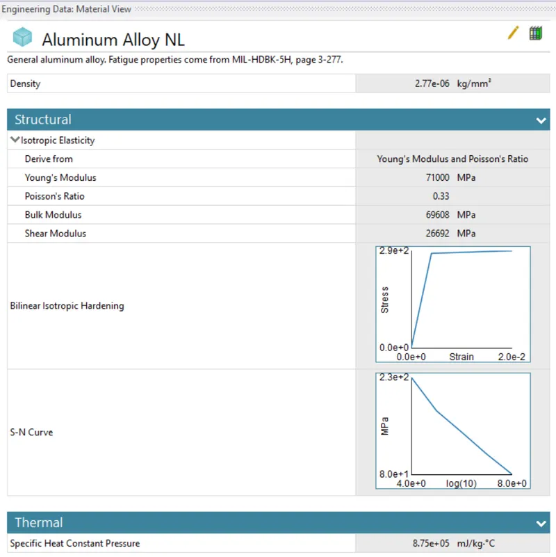
- For cover specify material as aluminium alloy NL, Polythelene to inner part and glass to screen and rest fingers as structural steel.
For Case-2-
- We have to add S-N curve for it in Aluminium Alloy NL.
- Now we have to import the model for that right click on the geometry tab and hit import>>then select the file from saved location and hit ok.
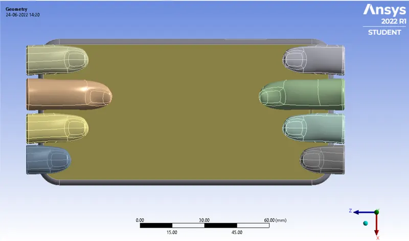
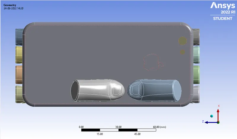
Case-1-
Case-2-
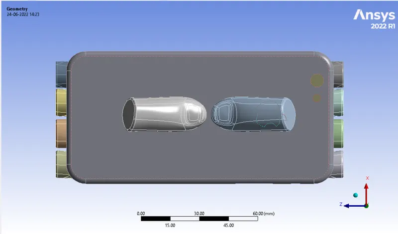
- The bottom fingers from their defined position to the given position X= 22.5mm & Z= 10mm.
- Now we have to open mechanical Model and wait for a while till our model loads.
- For cover select material as alluminium alloy NL.
- We have to now remane the mobile parts name and the proceed further for connections.
Connections-
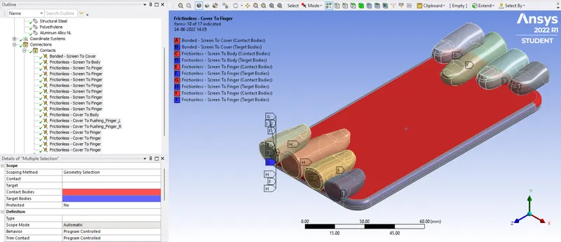
- Now we have to delete the two unspecified connections and then need to rename connections.
- Since Screen and covers will be sticked together so we will use bonded there and rest of them as frictionless.
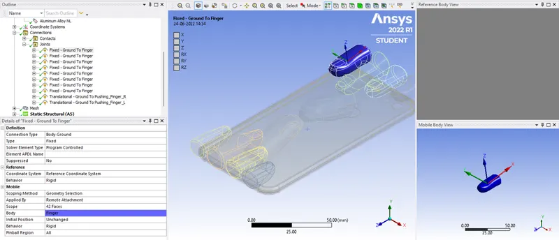
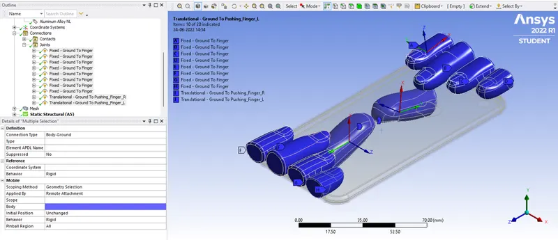
- Now we have to define joint loads, right click on connections>>joints>>select singers one by one and define joint loads.
Mesh-
For Case-1 & 2
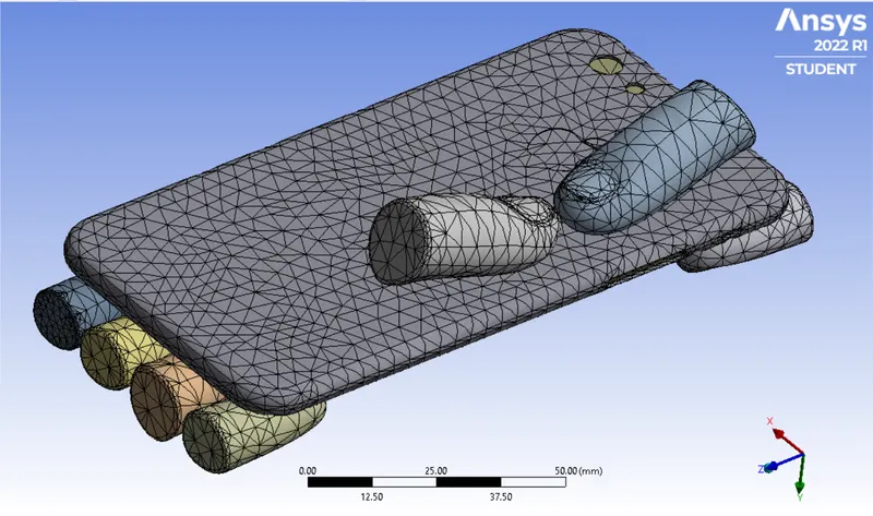
- Go to mesh then right click and the click on insert and select sizing.
- select size of 4mm as mesh size for bottom fingers and cover parts.
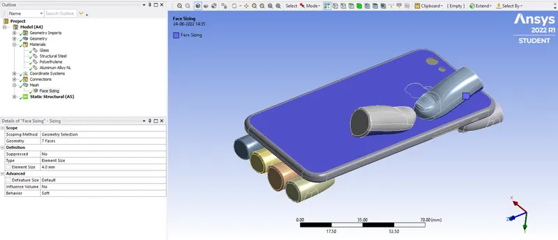
- For rest parts keep default mesh size.
Analysis setting-
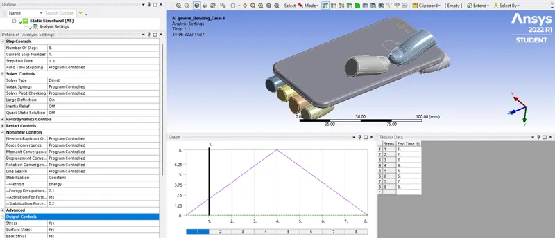
- Go to analysis setting and set number of set as 8 and refer below setting for steps selected.
- Keep output parameters as all yes.
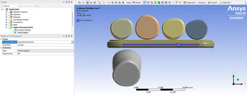
- Now we have to apply fixed support load to inner part of iphone on both edges as shown below,
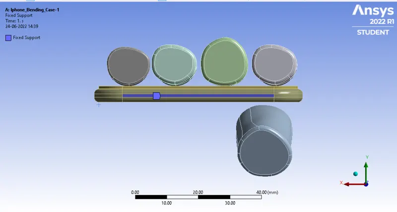
- Now we have to give dispalcement setting to punch as perbelow snap and select top and top two side faces of cover.
- Keep Y-axis free and rest as 0mm ramped.
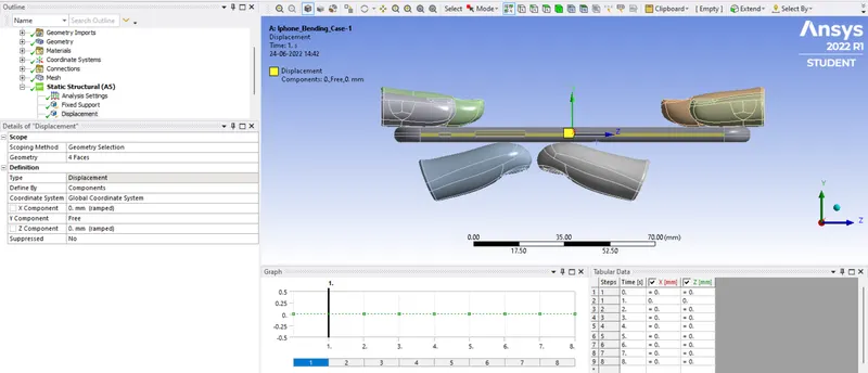
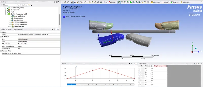
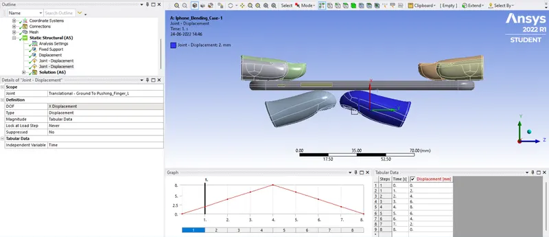
- Now for both fingers define the boundry condition as follows, here select whole body of fingers and apply displacement loads.
- Apply loads in X-axis only.
Solution-
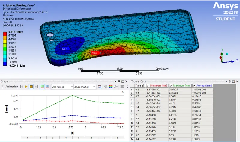
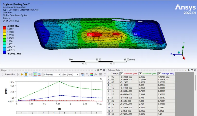
- Here we have to define directional deformation, to do so right click solution>>insert>>deformation>>directional, select Y-axis (for cover).
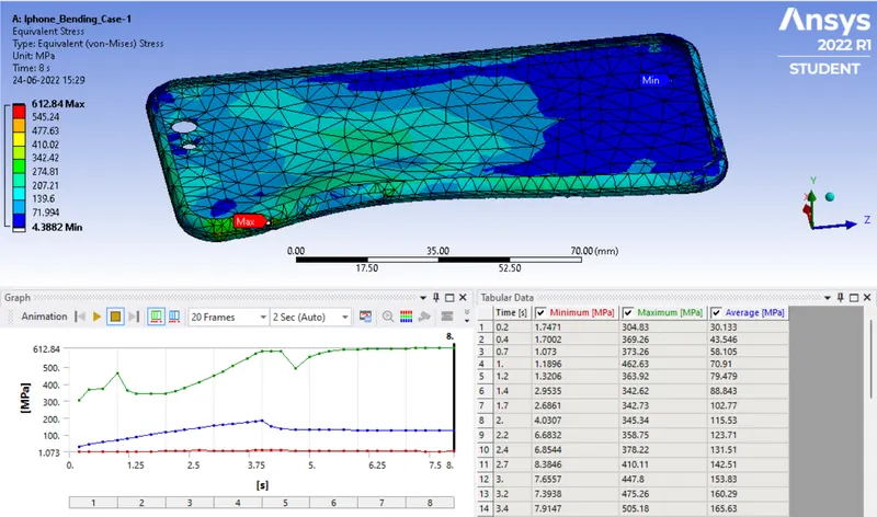
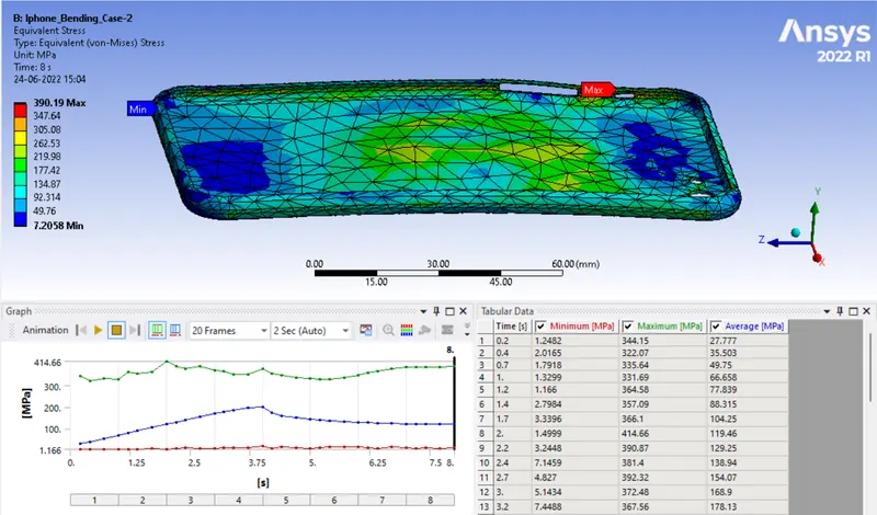
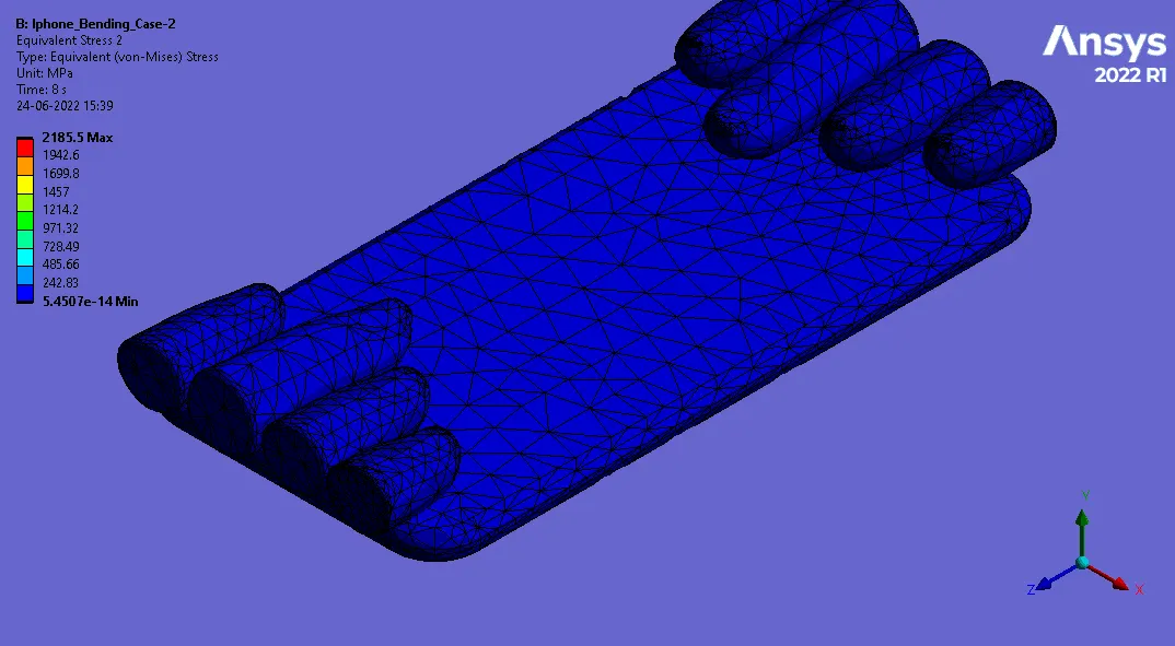
- Now for stress right click on the solution>>insert>>stresses>>equivalent (von-Mises) (for cover).
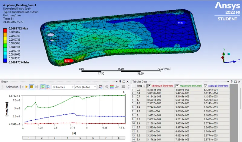
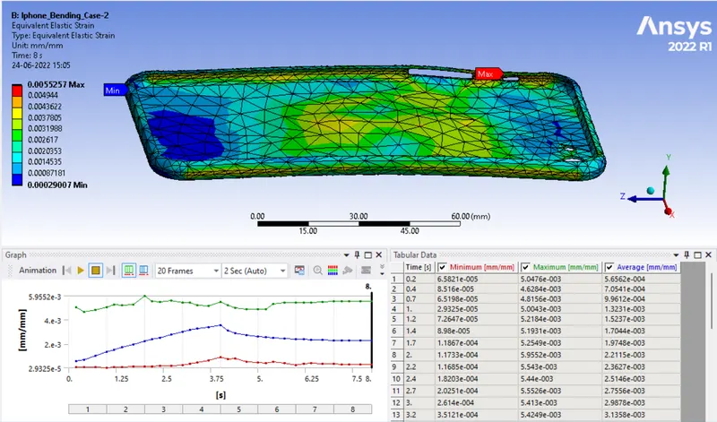
- Now for strain right click on the solution>>insert>>strains>>equivalent (von-Mises) (for cover).
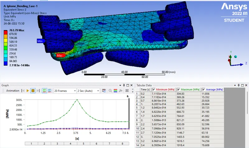
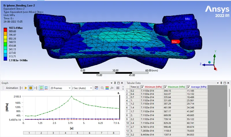
- Now for stress right click on the solution>>insert>>stresses>>equivalent (von-Mises) (for whole body).
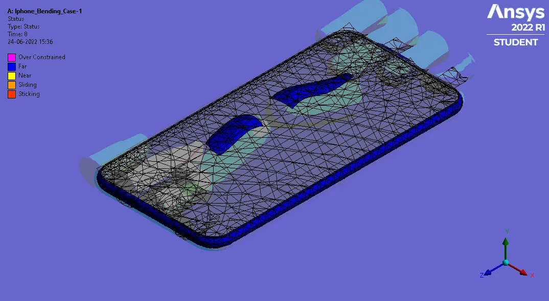
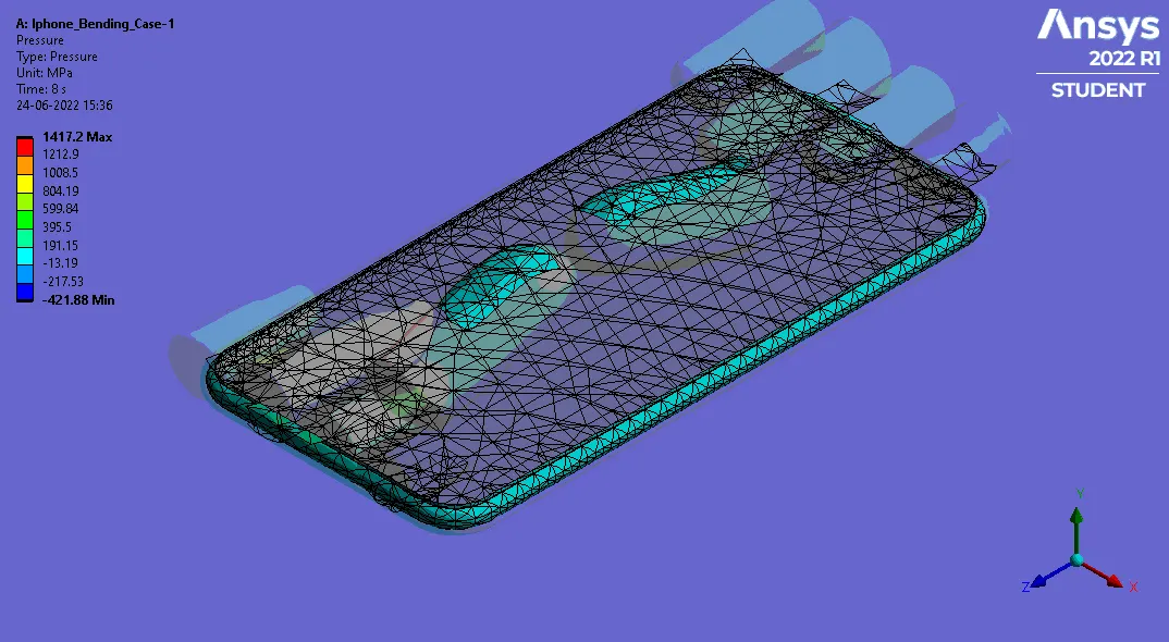
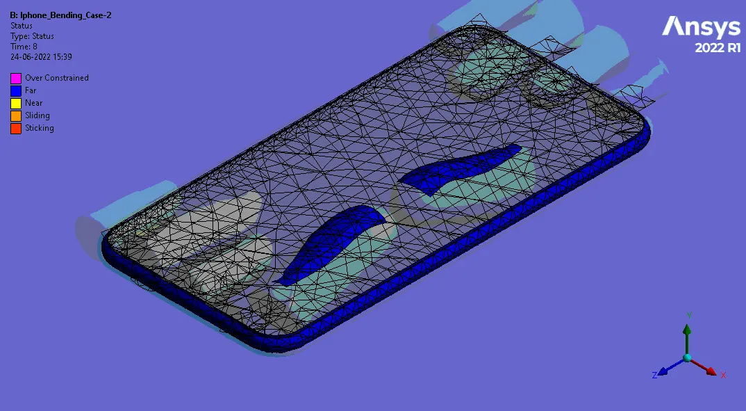
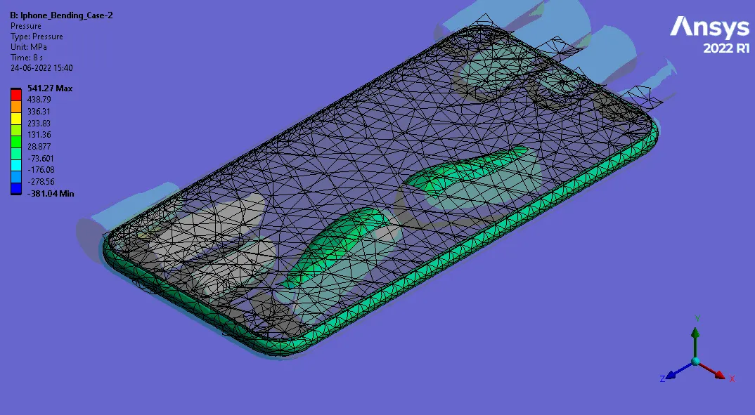
- Now for contact tool right click on the solution>>insert>>contact tool>>contact toll>>right click on contact tool>>pressure.
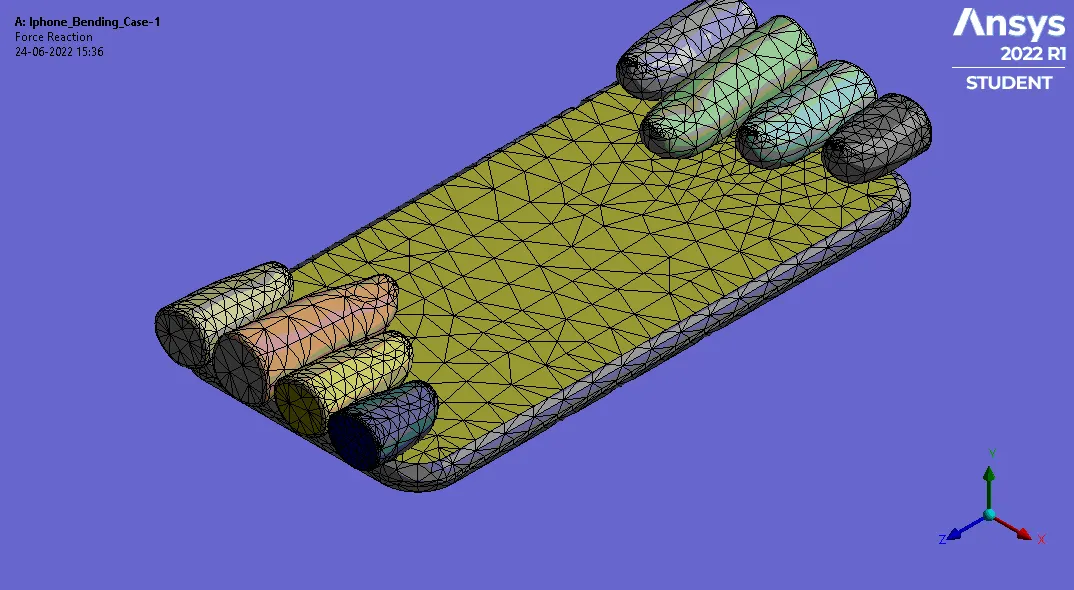
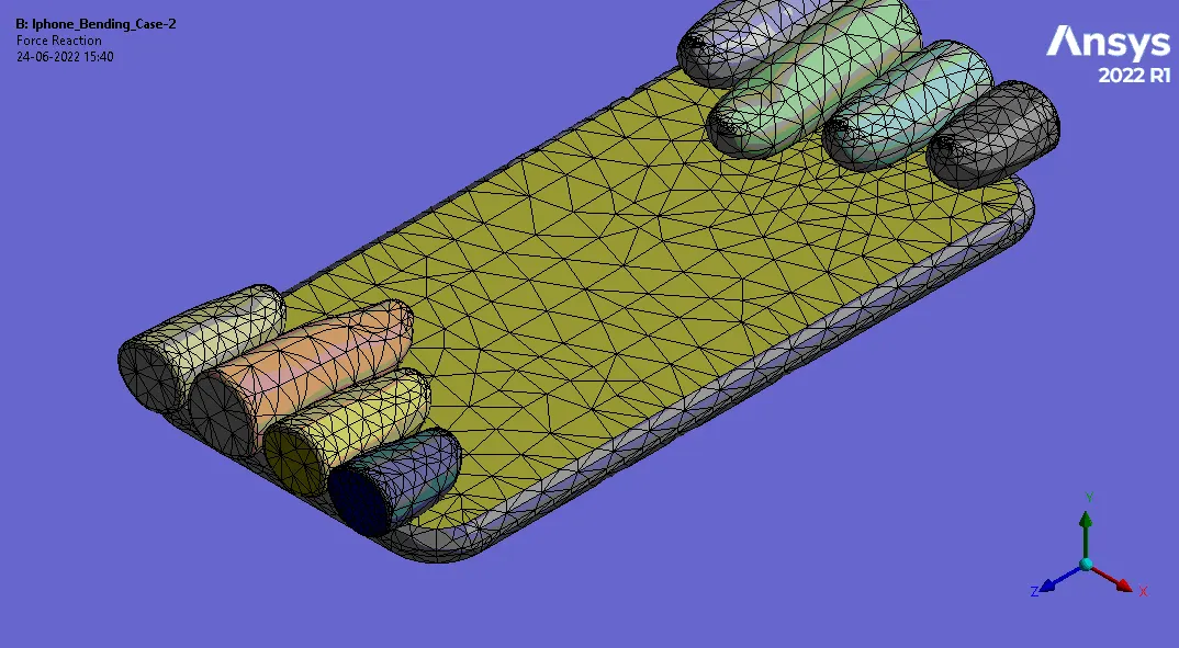
- Now for force reaction right click on the solution>>insert>>probe>>force reaction.
Case-1-
- Select the stress tool, right click on solution>>insert>>stress tool.
Note- for this reason we have defined tensile yeild strength in alunimium material.
Case-2-
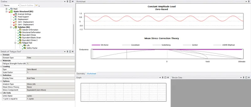
- Select the fatigue tool, right click on solution>>insert>>fatigue tool, again right click on fatigue tool>>life & safety factor for cover only.
- refer below settings in fatigue life.
Result-
Case-1-
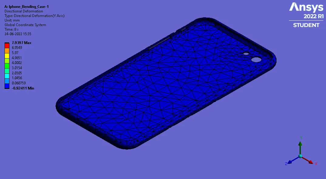
1. Directional Deformation-
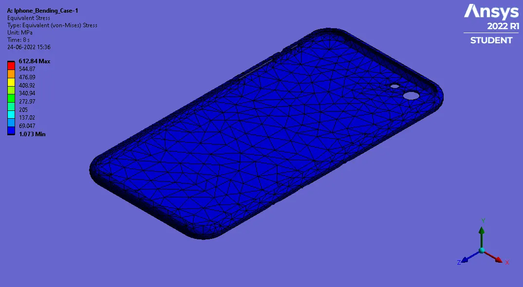
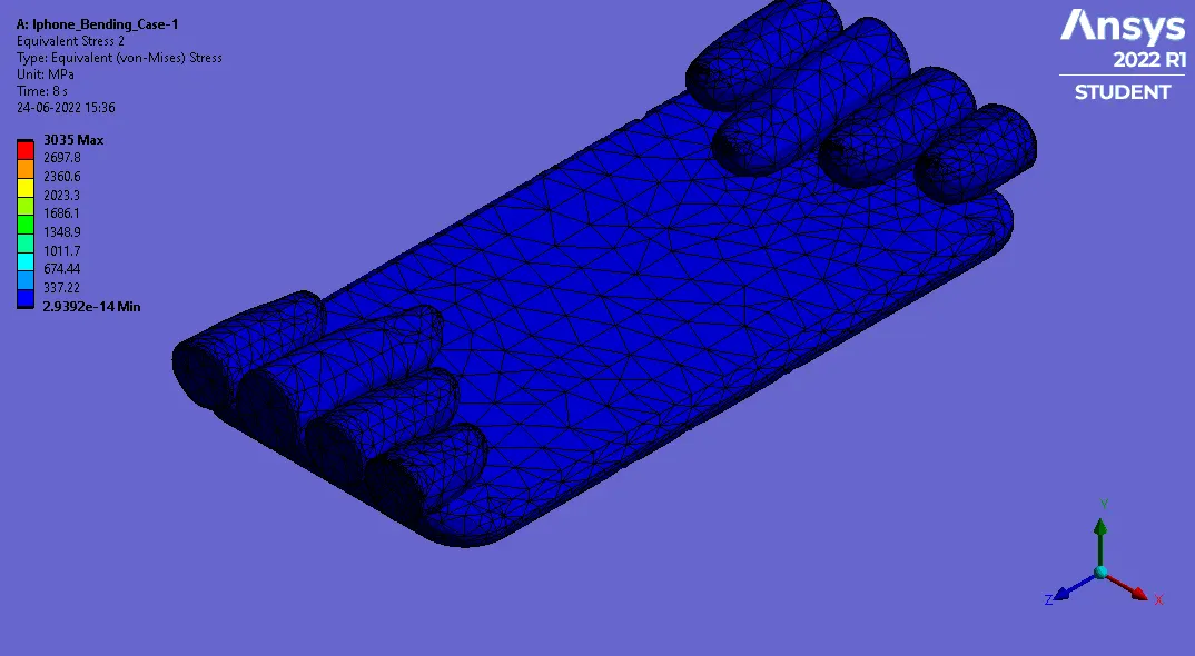
2. Equivalent Stress (For Cover)-
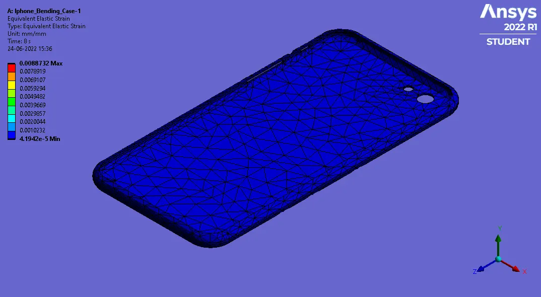
3. Equivalent Elastic Strain(For Cover)-
4. Equivalent Stress-
5. Contact Tool (Status)-
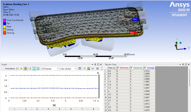
6. Contact Tool (Pressure)-
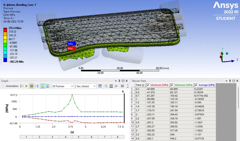
7. Force Reaction-
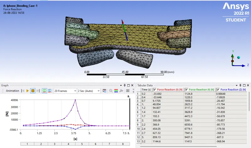
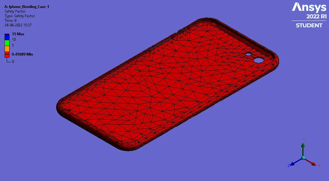
8. Stress tool (Safety Factor)-
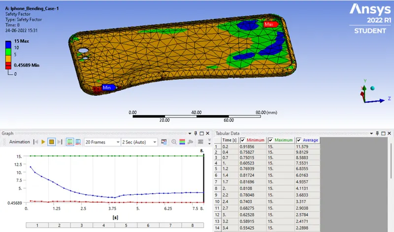
Case-2
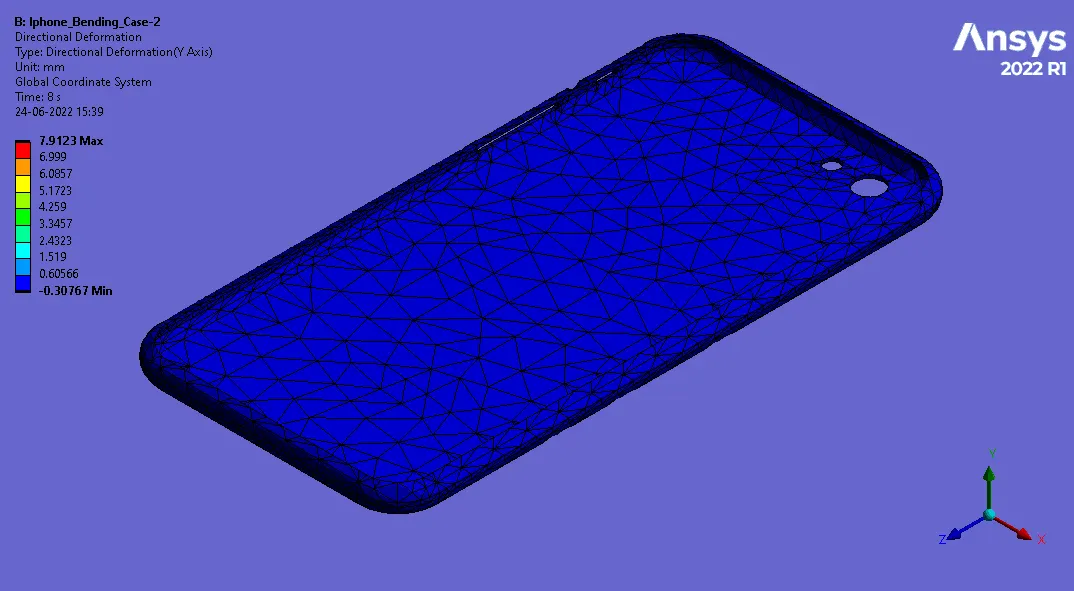
1. Directional Deformation-
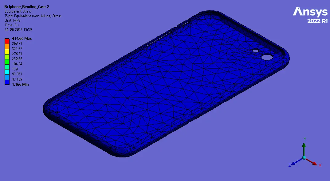
2. Equivalent Stress (For Cover)-
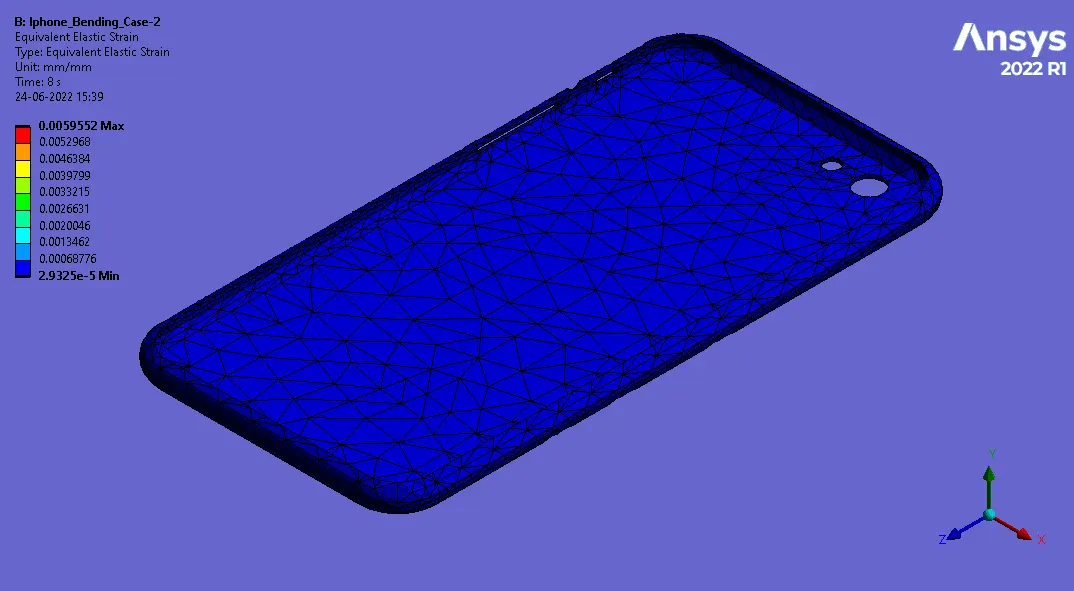
3. Equivalent Elastic Strain (For Cover)-
4. Equivalent Stress -
5. Contact Tool(Status)-
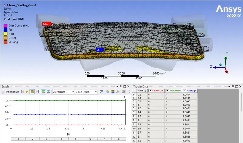
6. Contact Tool (Pressure)-
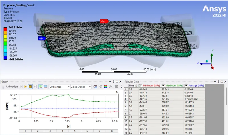
7. Force Reaction-
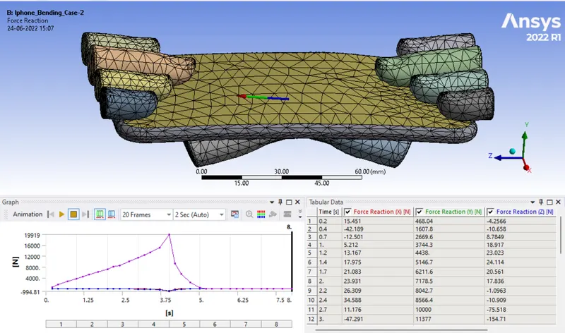
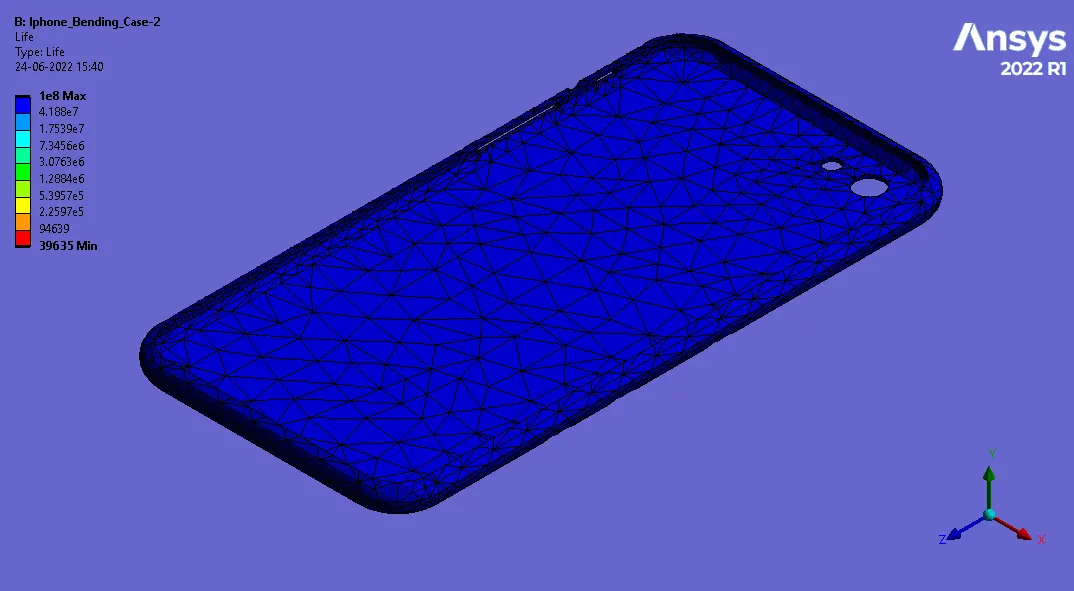
8. Fatigue Tool (Life)-
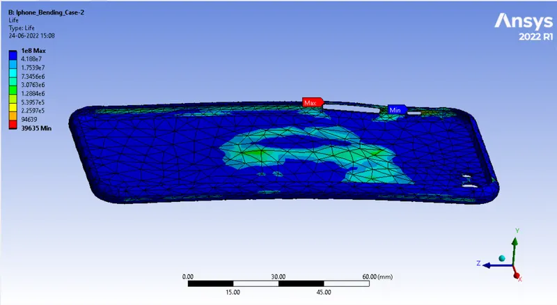
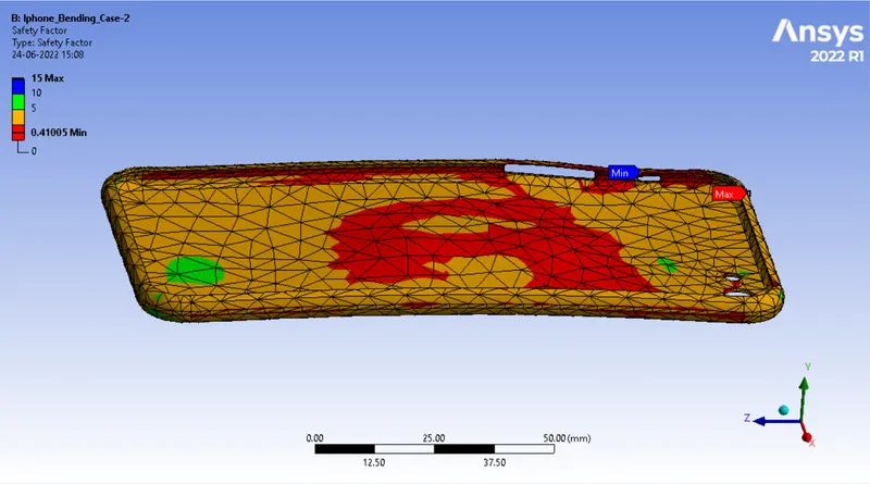
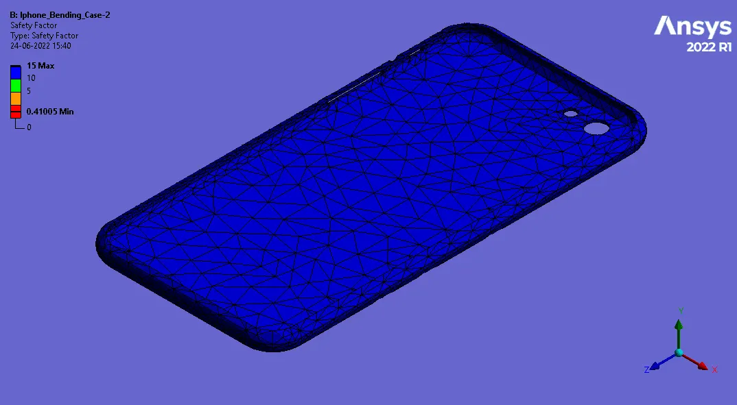
9. Fatigue Tool (Safety factor)-
Result Comparison-
|
Cases |
Directional Deformation (mm) |
Equivalent Stress (MPa) |
Equivalent Elastic Strain |
Safety Factors |
||||
|
Min. |
Max. |
Min. |
Max. |
Min. |
Max. |
|||
|
Case-1 |
-0.9241 |
5.4147 |
4.3882 |
612.84 |
0.00017 |
0.008873 |
0.45689 |
Stress |
|
Case-2 |
-0.3077 |
4.3806 |
7.2058 |
390.19 |
0.00029 |
0.005525 |
0.41005 |
Fatigue |
- From above table we can say that the max stress in case-1 is more than 1.5X of case-2 in which load is apply nearly at the centre.
- Also Strain is also lesser in case-2 as compared to case-1,which indicates that case-2 has less plastic strain.
- Also load applied on case-2 is nearly at at centre so load distribution is also proper, thats why it is showing lesser deformation as compared to case-1.
- Since from above deformation result we can observe that min value is in negative which shows that after removal of load cover tries to regain it's original shape.
- Safety factor for cases are nearly same.
Animated results-
1. Case-1
Directional Defromation-
Equivalent Stress (For Cover)-
Equivalent Elastic Strain (For Cover)-
Equivalent Stress-
Contact Tool (Status)-
Contact Tool (Pressure)-
Force Reaction-
Stress Tool (Saftey Factor)-
2. Case-2
Directional Defromation-
Equivalent Stress (For Cover)-
Equivalent Elastic Strain (For Cover)-
Equivalent Stress-
Contact Tool (Status)-
Contact Tool (Pressure)-
Force Reaction-
Fatigue Tool(Life)-
Fatigue Tool(Safety Factor)-
Conclusion-
- From above analysis and obdervation we can say that on repitative loads, iphone can with stand more load in centrally loaded condition.
- When it is loaded from side of cover in will fail and may break in ealry loading conditions.
- In both the cases stress is going beyond the max yield limit which can cause plastic deformation.
- To make iphone body more durable some filler material must be added to it to increase the strength.