Radar Mast & Final Assembly of Yacht
ASSEMBLY OF SUNSEEKER PREDATOR YACHT USING SOLIDWORKS
OBJECTIVE:
The objective of this project is to design and model Sunseeker predator yacht and all its parts using Solidworks and assemble it together to create the Photorealistic rendering of the yacht.
INTRODUCTION:
In this project, the Sunseeker predator yacht is designed using Solidworks. Here we use 2D sketches and convert them into 3D models. For that, we use surface modeling and solid modeling tools and features. When the parts are designed we assemble them by adding proper mates and constraints. Then we can understand about rendering a photo-realistic image of a yacht using Solidworks visualize and also using photo view 360.
DESIGN METHODOLOGY:
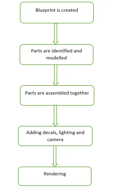
MODELLING OF YACHT:
The Sunseeker predator yacht consists of 9 parts. The following are the parts:
- Propeller
- Radar
- Hull
- Superstructure
- Radar Mast
- Front Seat
- Middle Seat
- Rear Seat
- Garage Door
Explaining the models:
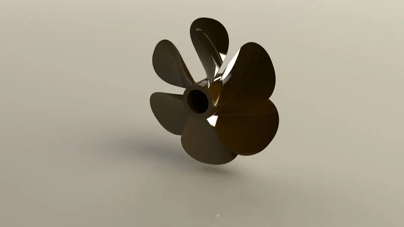
1. Propeller:
Propellers are used to move the yacht in forward direction, it provides the thrust for the movement. It is fitted at the rear end of yacht. Usually 2 or 3 propellers are provided according to the need.
Procedure:
- The centre portion was sketched using line and revolved using Revolved boss feature.
- A cut is made at the centre portion to fit the shaft. The sketch is made using circle and using cut extrude the portion is removed.
- For creating the blades a new plane is created using reference plane and then sketched using splines and using loft feature the blade is created and then filleted.
- Using circular pattern five blades were created.
- Proper appearance is added.
Result:
2. Radar:
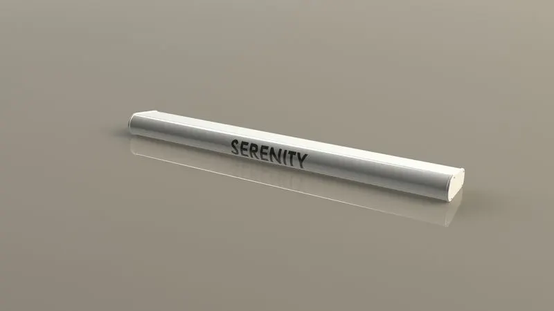
Radar is used for communication when yacht is sailing. It is used to transmit and receive signals from yacht to the controlling station.
Procedure:
- Sketch for radar is drawn using lines and extruded. Fillets are given to the corners.
- Offset tool is used to offset the side face sketch and extruded. On the extruded face hexagonal holes are made using cut extrude.
- Proper dimensions and constraints are given.
- The radar has a circular slot underneath which is created using cut extrude.
- Then using the mirror tool other half is mirrored.
- The text over the radar is created using the text option in sketch and then the split line was used to generate over face of the radar.
- The part is given with proper appearance.
Result:
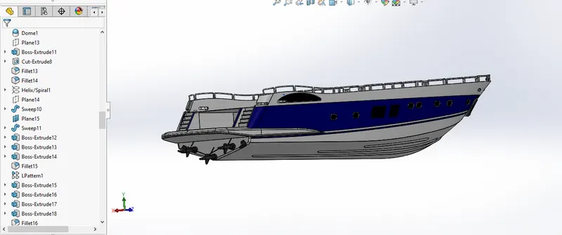
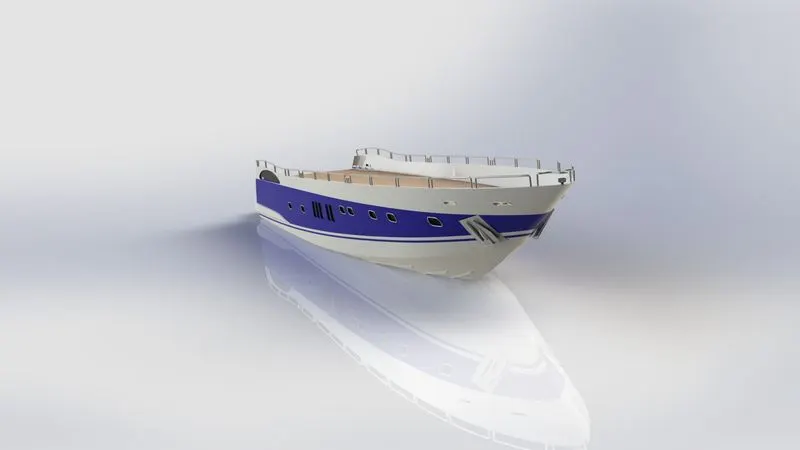
3. Hull:
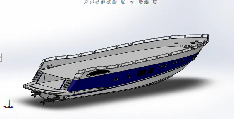
Hull is an important part of the yacht. It is the part to which all other parts are attached. It is a watertight structure.
Procedure:
- The blueprint of the yacht is inserted using a sketch picture feature and placed at proper planes.
- Using splines and lines the 2D sketch of side body and waterline are created and using projected curve feature it is projected into 3D.
- Using the surface loft feature the curves are lofted and the unwanted surface is trimmed using surface trim.
- Using surface extrude the back portion of yacht is created.
- All the surfaces created are knitted to avoid gaps.
- Using surface fill the deck and the side surface is closed.
- Then using shell feature the selected surface is made into a shell.
- Using offset feature the outer edges are offset and extruded to make bottom portion of the hull into a solid body.
- Fillets and chamfers are given to the sharp edges.
- Using reference plane a new plane is created and sketch for the windows are drawn. Using cut extrude cuts for the windows are made and filleted the corners using fillet and chamfer.
- For creating smooth edges around berth window a new plane is created and a circle is sketched and using sweep feature a smooth sweep around the edge is made.
- The bottom of the yacht has rails which are created using boss extrude and chamfer is applied.
- The cable rollers were created using extrude boss, revolve and dome. Cut extrude was used to cut through the extrude that made before. Helix sketch was used to create rope and using sweep the rope was created.
- Rope hangers were created using slot sketch and extruded. Using linear pattern an extra hanger was created.
- The staircase was created using boss extrude.
- The railings around the hull and staircase were sketched using blueprint and then using sweep feature the profile of railing was swept along the path.
- The axles of the propeller were created using revolve feature and using 3D sketch.
- The anchor was created by sketching the first half and extruded, then the other half was mirrored.
- The garage portion was created using cut extrude and the portion was saved for later use by using split feature.
- Finally the other half of hull was created by using the mirror feature.
- Proper appearance was given to the hull.
Result:
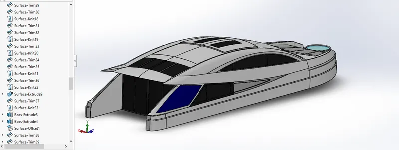
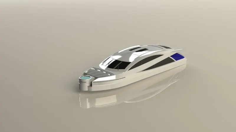
4. Superstructure:
A superstructure is fitted onto the hull. It is the main compartment for the passengers and the goods.
Procedure:
- To model the superstructure the deck surface from the hull was imported.
- Sketch for the superstructure was drawn looking at the top view of blueprint. Using surface extrude and lofted surface feature the surface is created. Unwanted surface was trimmed using surface trim.
- Surface knit was done.
- Using ruled surface the net surface of the sidewall was created with an angle.
- Using projected curve the path for the surface above the window is created and using 3D sketch the profile is created then using surface loft the surface is created.
- The windshield was created by extrude cut and the wipers were created by using 3D sketch and reference plane with the help of swept boss.
- Using extrude cut the backdoor of the superstructure was created. The sharp edges were filleted.
- All the surfaces are knitted properly and converted into a sold body.
- Wipers are created using 3D sketch and extruded, wiper arms are created using sweep boss.
- The upper surface of the superstructure is renamed as Radar Mast Reference Surface and used as a base for the radar mast.
- Then the other half was mirrored and proper fillets and appearance were added.
Result:
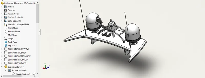
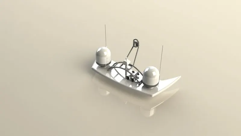
5. Radar Mast:
A radar mast is a frame that supports the radar. It is positioned at the aft above the superstructure surface.
Procedure:
- The blueprint model is used to sketch the base of radar mast. Using lines and splines the sketch was drawn. Then using boss extrude the sketch was extruded.
- Then using revolved feature the upper portion of the body is created.
- The antenna for radar was created using the extrude boss.
- The Lampstand was created using the sweep feature and projected curves.
- The horns were created using revolve, dome and shell feature.
- Chamfer and fillets were applied.
- Proper appearance was given to the part.
Result:
6. Front Seat:
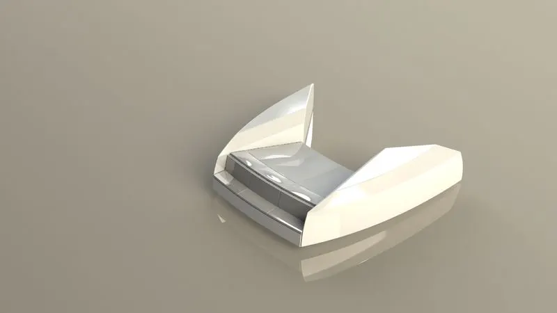
Front seat is designed in such a way that the passengers can relax on it. The seats are fully reclined back to make it comfortable.
Procedure:
- Deck surface was imported from the hull. Connecting the deck surface the side of seat was created, using surface sweep.
- Surface fill was used to fill the top surface of the seat.
- Using surface knit the surfaces are properly knitted to avoid gaps.
- Using mirror tool the other half was mirrored.
- The front seat and beds were created using cut extruded, fillets were given.
- The part was given proper appearance.
Result:
7. Middle Seat:
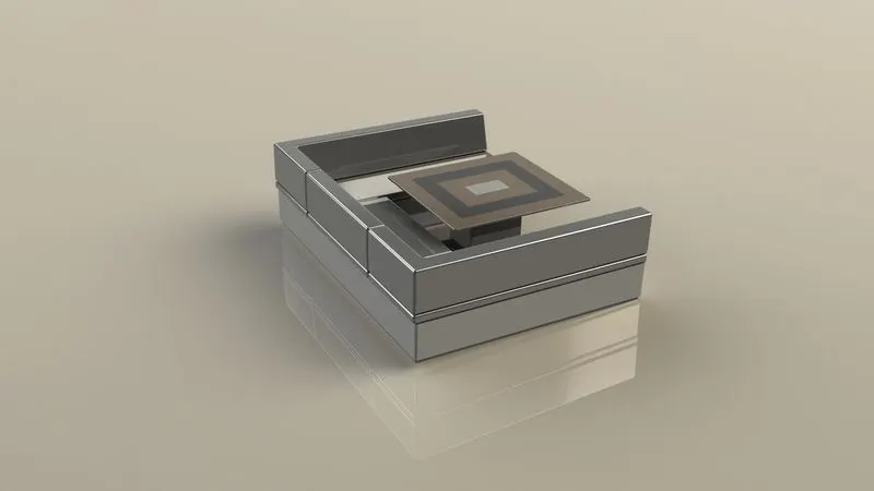
This seat is placed after superstructure. The middle seat is designed in such a way to give luxury and comfort.
Procedure:
- Using lines the sketch of the seat was drawn and using boss extrude it was extruded. Fillets and chamfers are given.
- Using reference planes the planes for sketching the cushion and backrests were created.
- Using extrude feature the sketch was extruded. Using mirror feature one side of the seat was mirrored.
- The table was created using extrude boss and cut extrude.
- Fillets were given to the sharp edges.
- Proper appearance was given to the table and seat.
Result:
8. Rear Seat:
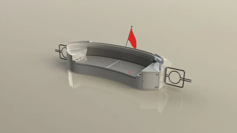
The seat is placed at the end of the deck. At both ends of the seat, there is a storage facility. There is a flag placed at the back of the seat.
Procedure:
- Sketch for the seat was drawn and using a swept surface the back portion of the seat was created. The extra surface was trimmed using surface trim.
- Inside the sketch we used extend entities to extend the lines.
- The flag post was created by revolve feature. The flag was sketched using splines and using loft surface it was created.
- The tail lamps were created using extrude boss.
- To create gates new reference plane was created and using a swept surface the gate was completed.
- Using mirror tool the other half was mirrored.
- To remove the gaps the all surfaces were knitted using the knit surface feature.
- Fillets and chamfer were given to the sharp edges.
- Part was given with proper appearance.
Result:
9. Garage Door:
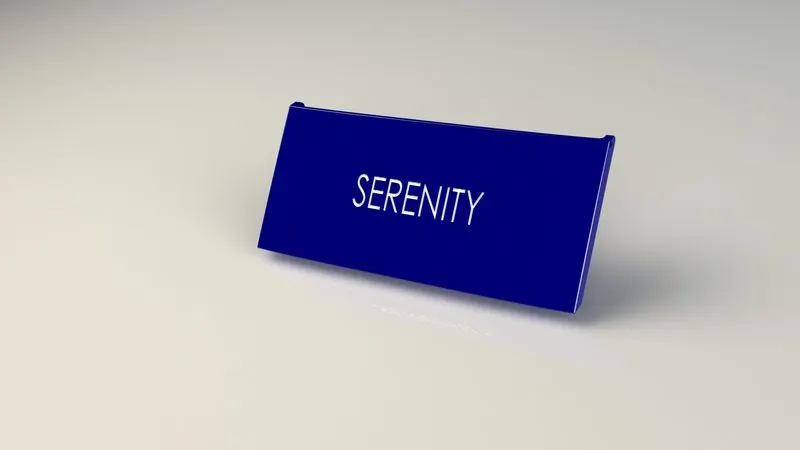
Door to close the garage space on the yacht. It can be manually or electrically operated.
Procedure:
- From the hull part, the split model was imported.
- Using extrude cut the door was created.
- Using shell feature the solid body for the garage door was created. Fillets and chamfers are given.
- The holders for the door are given using extrude cut.
- Using mirror tool the other half of the door is created.
- Using split and sketch feature text over the garage door was given.
- The part is given with proper appearance.
Result:
ASSEMBLY OF YACHT:
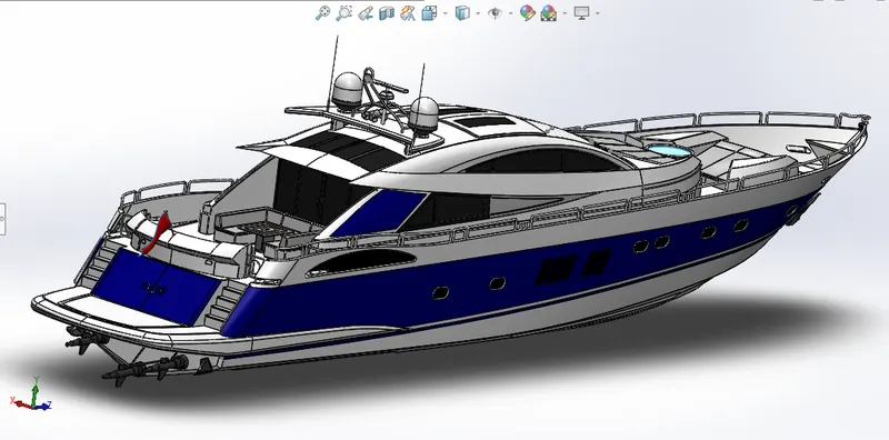
In assembly, the parts we created are mated together to form the whole model.
Procedure:
- Import all the parts manually by using insert component option.
- Fix hull, superstructure and Radar mast automatically. By clicking ok.
- The other parts are manually fixed using necessary mates and constraints.
- All the parts are fully defined.
Rendering of the model of Yacht in SOLIDWORK visualize
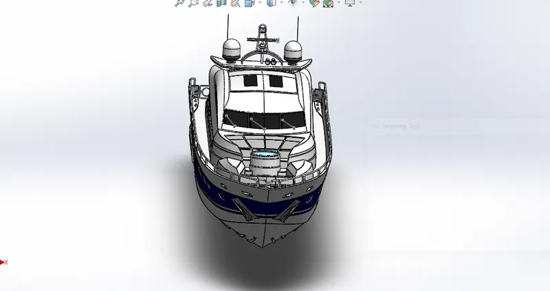
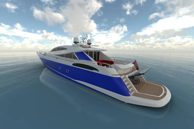
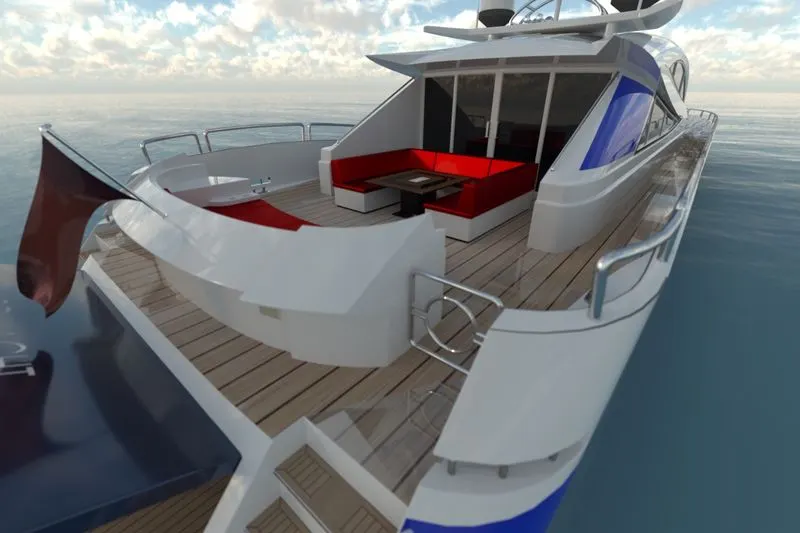
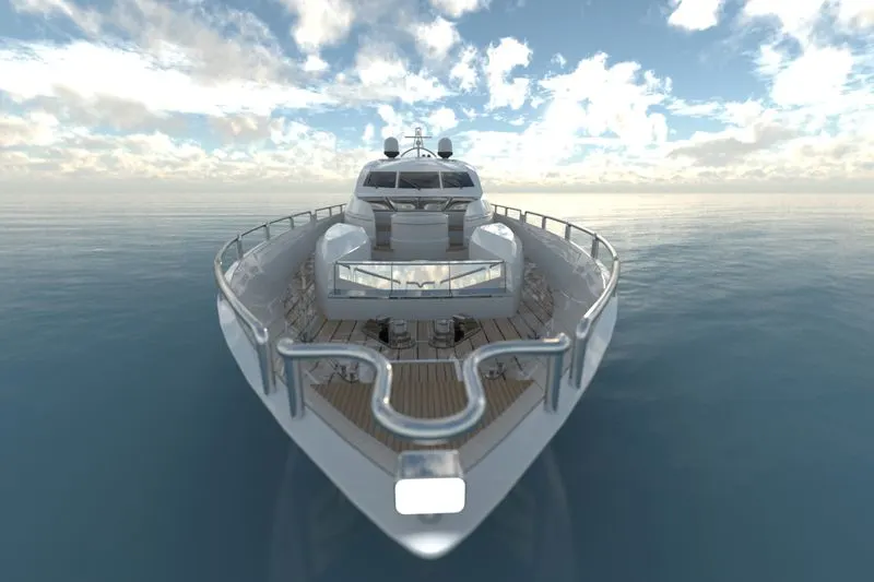
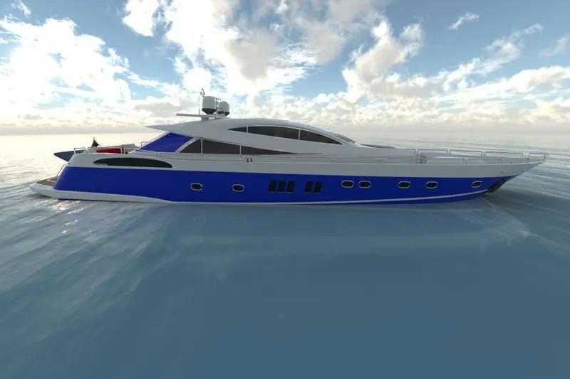
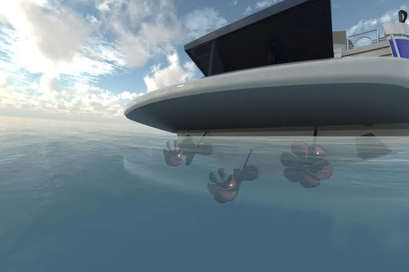
SOLIDWORKS VISUALIZE is the software used for rendering any model created in the SolidWorks. In this HDR environment, lighting conditions, camera position, etc. can be changed for getting rendering images. Following are some of the rendered images of Yacht in different environment and colours.
Conclusion
Thus the Yacht was successfully modelled using SolidWorks and rendered using photoview 360.
Learnings from the project
Generally when we surf the internet for models for practice, we get many models and engineering drawings in solid modelling. As we don’t get enough materials to practice surface modelling, there exists a situation where surface modelling should be practised out of own interest.
In this project “Yacht”, I had a very good opportunity to explore almost all commands in surface modelling in SolidWorks. This project gave me a very good experience and opportunity to explore the different ways to create complex curves and surfaces and convert the surface model into solid model. As surface modelling requires precise curvature during the sketching stage else it will result in bad geometry.
There are a number of ways to create a surface like extrude surface, loft surface, sweep surface, fill surface, extend surface, ruled surface, boundary surface etc. all the commands are used to create or form a surface. But all these commands cannot be used all the time, for instance, with fill command we can create a surface and with extrude command we can create a surface, but we should have a very good strategy to create the desired surface, so that the model could be created effortlessly in very short time, which could be obtained only by out of the box thinking and experience and this project “Yacht” paved the way for it.
Trim command and surface knit are very useful in removing the excess part and joining two surfaces without any gaps respectively. 3D sketches were also used in this project and it is very handy tool to create 3-dimensional curves and profiles.
Working in this project “Yacht” was a very good experience. I had the opportunity to learn the way of creating sketches in a better way and to explore features, especially in surface modelling, so that the model could be done a better way, in less time and effort.