Week 12 - Project-1
Aim: To Mesh the given side door of a passanger vehicle under given quality criteria.
Quality Criteria:
Target Element Length = 4mm
| S.N | Quality Criteria | Value |
| 1 | Aspect Ratio | 5 |
| 2 | Skewness | 45 |
| 3 | Warping | 15 |
| 4 | Taper | 0.5 |
| 5 | Min. Length | 2mm |
| 6 | Max. Length | 6mm |
| 7 | Min angle Quad | 45 |
| 8 | Max angle Quad | 135 |
| 9 | Min angle Tria | 20 |
| 10 | Max angle Tria | 120 |
| 10 | Tria % | 10 |
Component Study: The component is a plastic side door trim body with variable thickness
We observe the following things:
- The part consists of a central base which is of 2.8mm thick and the rest of the features are of various thickness.
- The parts have some solid features,which are unsuitable for 2D meshing,which is our objective.We will ignore these features as well as any feature of thickness more than 6mm.
- There are some geometrical errors, and free edges, which we have to correct before we move on to mid surface extraction.
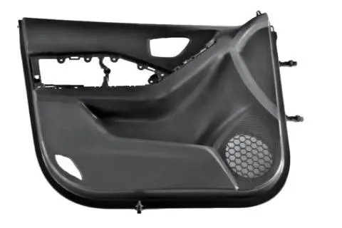
Side door image
Procedure:
A. Geometry Cleanup:
1.Import the Side_door_edited.hm into hypermesh.
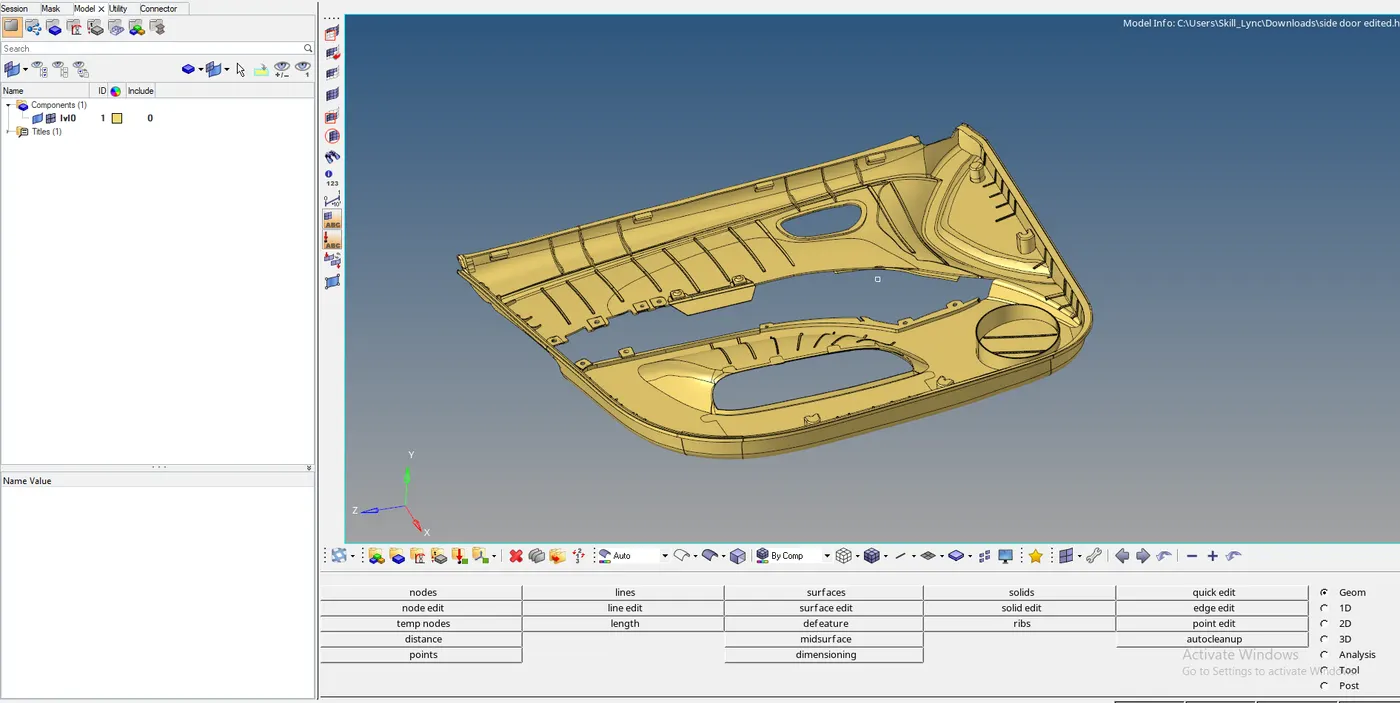
FIG 1: SIDE DOOR CAD GEOMETRY
2. Delete the solids and measure the dimensions at various places.
3.Defeatures all the ribs for coverting all ribs into the proper rectangular shape so that it will be easy to measure thickness of the ribs while assigning thickness.
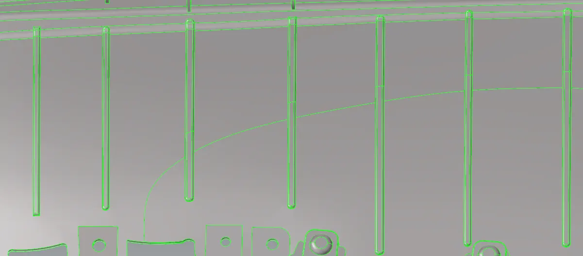
For defeaturing we go into Geometry>Defeature>surf fillet>put min radius as 0.1 and max radius as 12.

After defeaturing the ribs are look perfectly into rectangle shape.
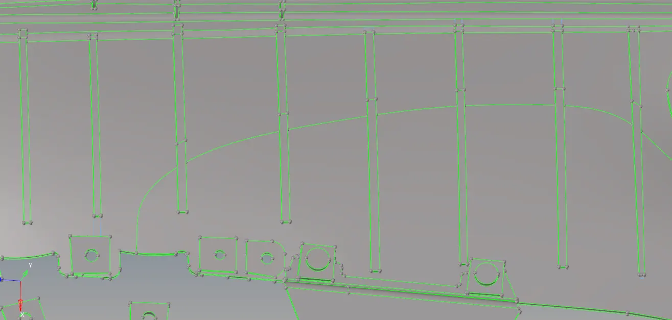
4. Tools>Organise the components into different collectors.
B.Midsurfacing:
So, a.as we know this model is of plastic component means have varying thickness so we extract mid surface part by part
first we extract mid surface of base part by using manual mid surfacing method.
for this we go to Geometry>Surface Edit>offset> offset value as 1.4 as thickness of base surface is 2.8mm.

b.For ribs sections, we can go to Geometry>line>Midline now select two line one by one to create mid line in between.

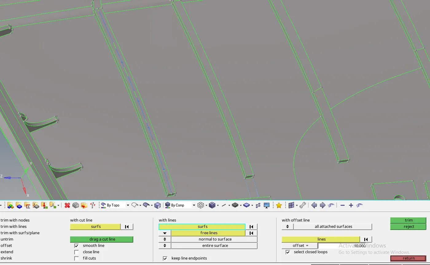
After creating midline ,we go to surface edit>trim with line>with line
now we project this line to base surface and create a surface between these two lines.
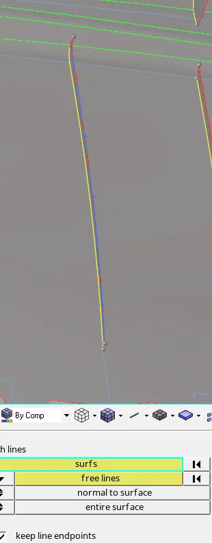
c. another method we can use for extracting mid surface of ribs by Geometry>Midsurface>Final edit tool select surface1 and surface2 .

after creating mid surface from this method we extend the mid surface of rib to the base mid surface by go to Geometry>surface Edit>Extend> change into extend over edges. The rib will extend on base by creating yellow line.
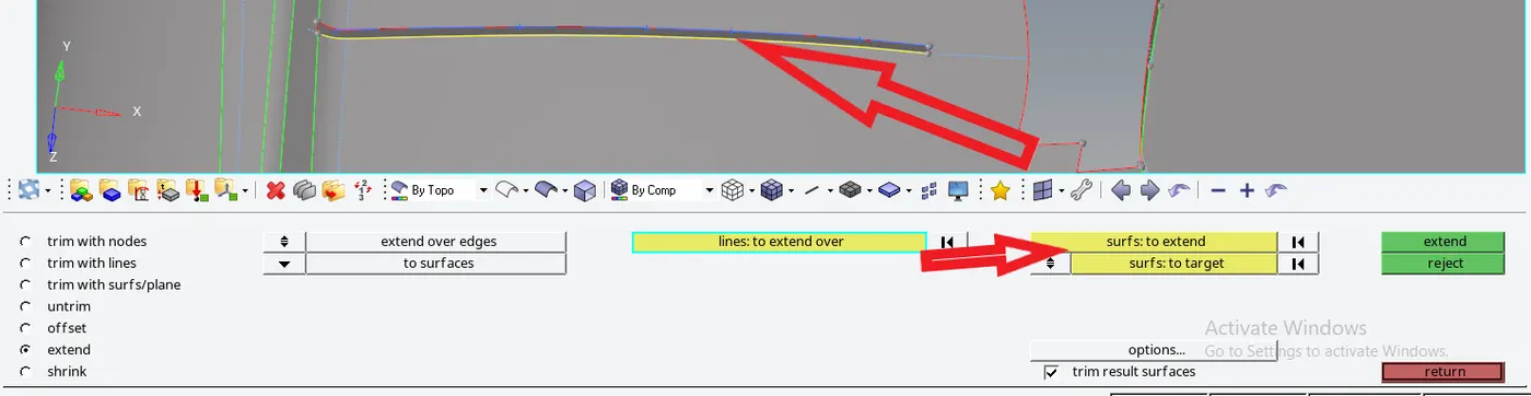
By using these three methods for extracting mid surface we can extract mid surface of all the parts of the model. After extracting the mid surface our model would look like as shown below:
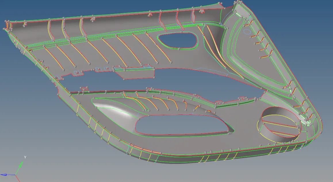
Midsurface Extraction of side door
C. Meshing:
1. Divide the side door model into small parts so that meshing will be fine with less trias.
2. Automesh the surface for proper mesh flow after setting up mesh parameter and quality criteria parameter.
For mesh go to 2D>Automesh select element size as 4mm .
3. Next step is to remesh the model to address the quality issues highlighted in above step.
Fot this we have various tools.
We can remesh any uneven region of the mesh by selecting the elements and mesh them.
4. To improve mesh quality we use Remesh,Drag tria, combine element,Smooth, Project nodes.

After meshing all components part by part ..the meshing surface somewhat looks like below figure.
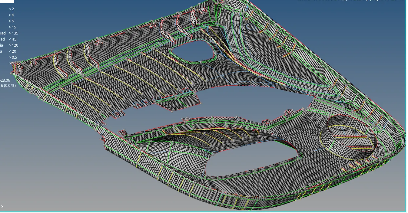
3.Clean up the elements to stay within quality criteria using Element optimize , place nodes, drag tria elements. Check for rotational quads .trias near fillet portion trias on ribs , if these are present then remove this also minimize the quality errors zero and tria percentage as low as you can.
Quality Index:
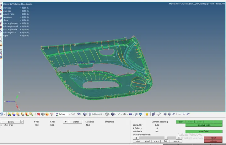
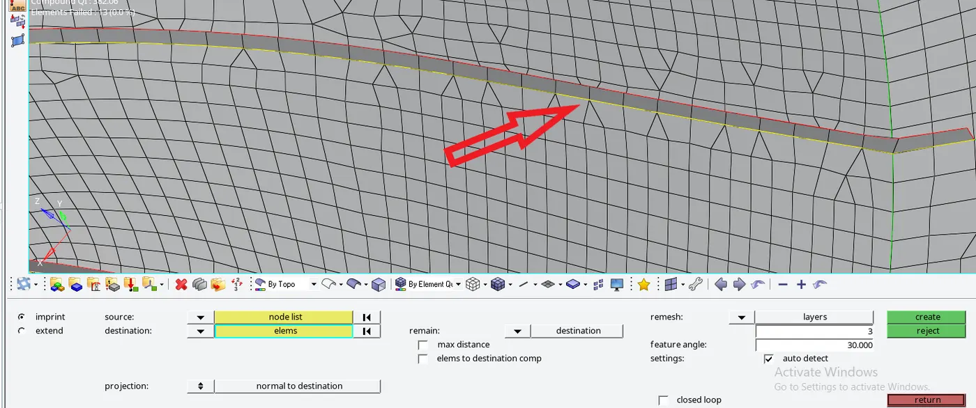
4. Check the connectivity of the mesh on ribs with mesh on surface if there is free edges present then clear it by using mesh edit option.
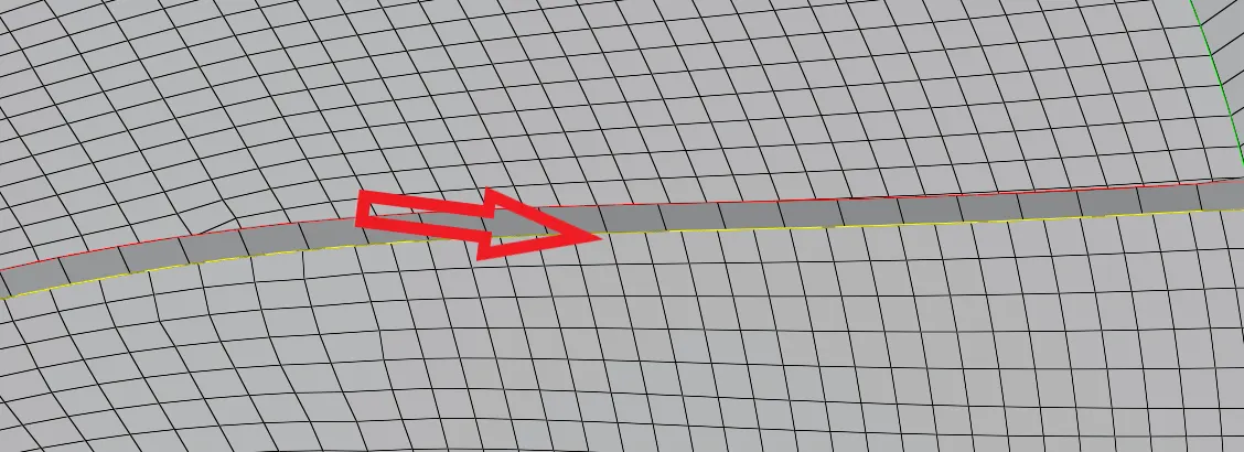
As shown above there is no connectivity between two mesh surfaces.
To fix it we go to 2D>mesh edit We select source as rib node and destination as surface elements. Select remesh layer as 3 then click on create.
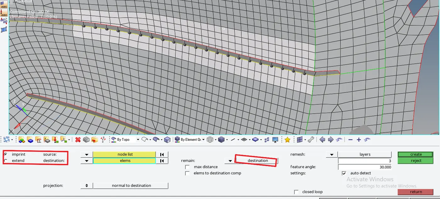
The result will destort total 3 layer of mesh but fix node connectivity between both mesh surfaces,then we remesh these layers to get proper mesh.
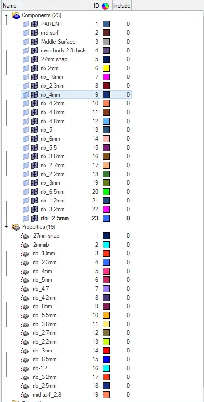
5. The various midsurfaces are extracted into separate collector as per their thickness and assign their thickness in property tab as
shown below:
6. Finally we turn on 3D representation of 2D elements and check how well the mesh is captured.
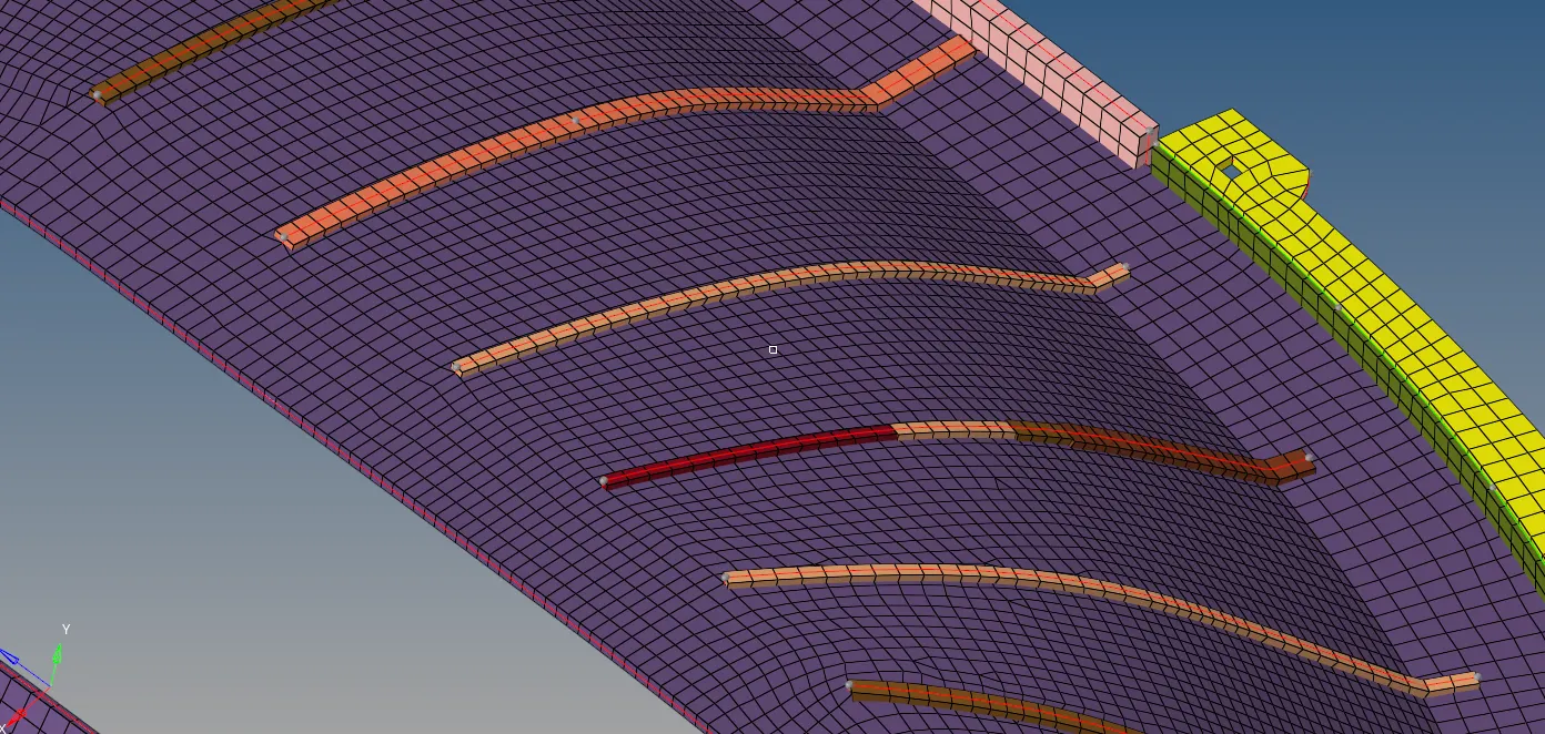
We can check topology capture accuracy for every feature in this way.
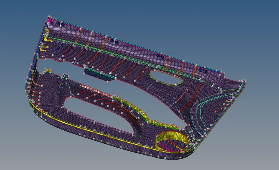
Result : The following component is meshed as per required quality criteria.
The generated mesh is checked for quality criteria and topology capture.