Assignment 2
1.Check the material properties of the rail component and calculate the speed of sound in steel rail=_______
speed of sound in steel rail C=`sqrt(E/rho)`
C=`sqrt(210000/0.0078`
C= 0.5188.74 `mm/ms`
2. The length of the rail is about 1000 mm.calculate the time takes for a shock wave to travel from one end of the rail to the other.
l=1000 mm , c=5188.74 mm/msec.
swo time taken for the shock wave = l/c = `1000/5188.74`
= 0.1927 ms
Sign convention should be in the gram , mm . milisec, newton, newton-mm.
| g | mm | ms | N | N-mm |
3.Time for sound to travel length of rail=_0.1927 ms.
5.Set the frequency of animation output to a time that will give 20 animation steps(/ANIM/DT)
run time =0.1927 ms
animation steps=20
freq. of an animation= `0.1927/20`
= 0.0096
4. open file in radioss go to Card>ENG_ANIM_DT and set the value of Tfreq(frequency of animation output) to 0.999 so that we can get 20 animation steps after running.
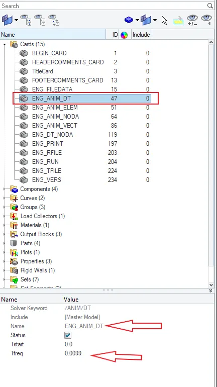
After editing engine animation card , we move to the RUN Card ,and set the value of the Tstop as 0.1927 ms. So that the stress wave can be monitored, moving from one end of rail to other during impact this will require a termination time wich is equal to the time it takes for the sound to travel the length of the rail.
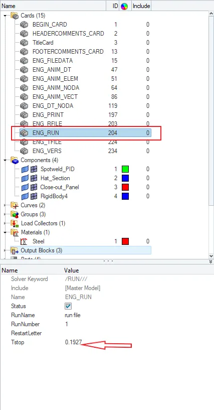
then we check ENG_PRINT Card the value of Nprint is -10 or not ..if it is -10 then we move to run the file.
After setting all the values we go to analysis>Radioss then select file in which we run the animation file and select Radioss.


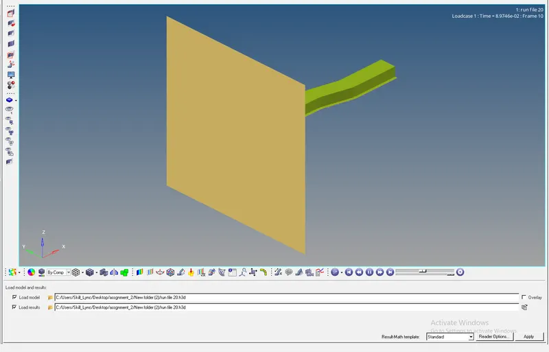
After running the radioss file we get the image like this and get the 20 animation steps.
7. objective
Generate FE model of the given model using the given quality criteria.
Target tet size= 5mm , hex size= 10mm , tet collapse = 0.15.
Procedure :
- Open the given cad model and understand the geometry for the meshing.
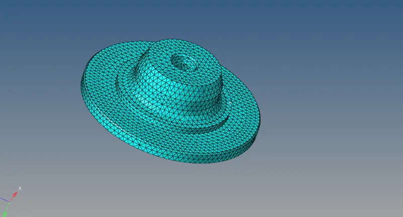
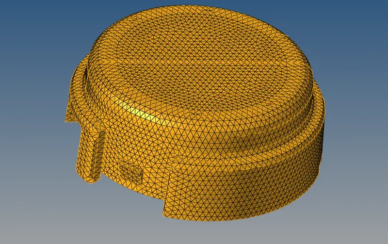
- Perform 3D meshing- Tetra mesh
- Check for the tet collapse.
In 3D panel tetramesh
First perform 2D meshing with trias on the surface of the model
Go to tetra mesh, give parameter such as tetcollapse and min size element
Select 2D trias and perform the mesh.
Hexa mesh of arm bracket:
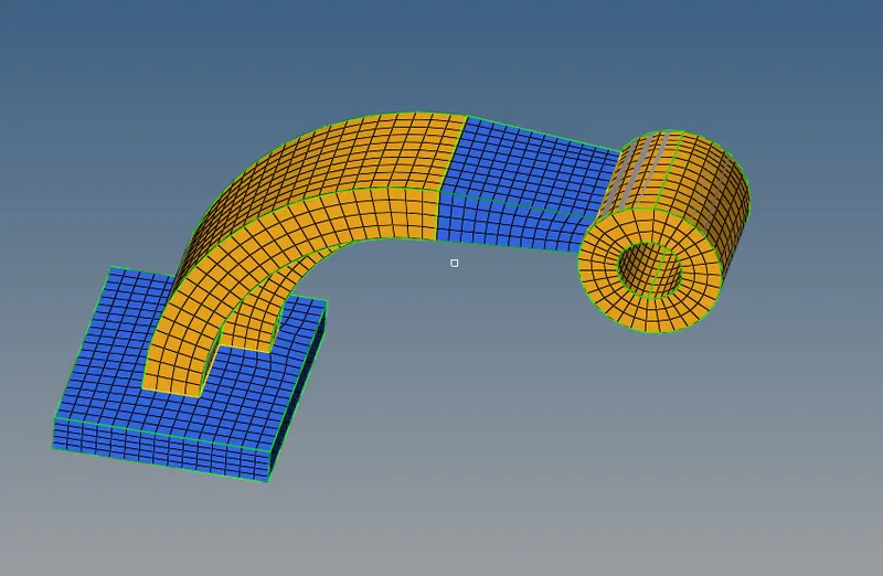
For the creation of hexa mesh in the component, a 2D mesh is created on the surface and then drageed using different options available in the hypermesh panel, to be converted into its 3D mesh.
First the base of the arm bracket is 2D meshed with mixed option and the mesh size of 10mm.
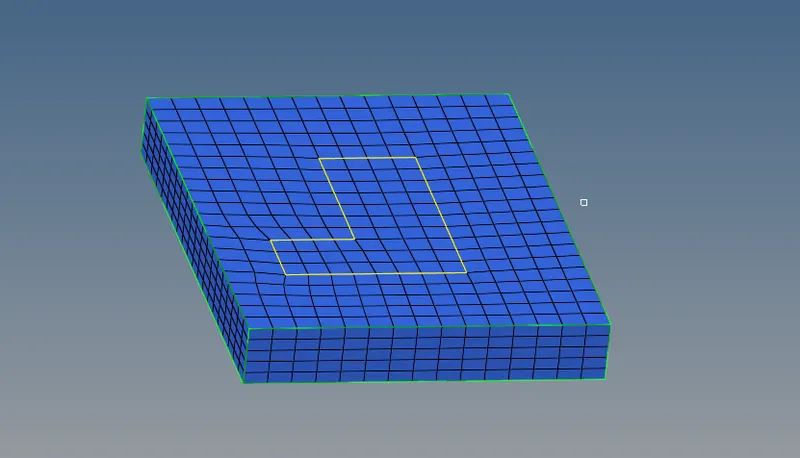
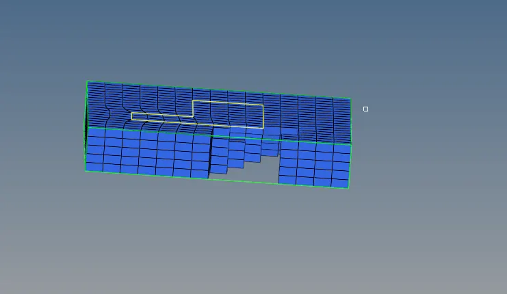
The 2D mesh is then dragged using element offset.
For Arm_curve , the elements are dragged using 'spin' command in a curved manner to get the required mesh configuration. The centre of the arc was obtained using selecting points in the arm-curve arc.
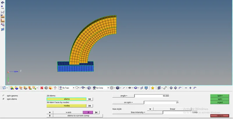
For the straight arm, the mesh is dragged using 'linear solid' option to build a mesh as shown below:
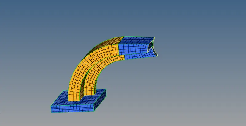
For rest of the mesh, a 2D mesh is first created on the circular mesh. Thes using the 'solid map' option , then the 2D meshed is dragged along the x-axis but the connectivity is maintained.
Conclusion:
- the engine file was modified as needed.
- Hex and tetra mesh are formed for the given models
the .hm files are attached with given report.