Week 12 - Project 6 - Master Section Development
Aim:-To Design B-Pillar Through Master Section Development And Write a Detailed Report.
Given:
-A-Surface
-Master Sections
-Distance Between Ribs Should Be 50mm
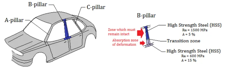
Pillar in the car
-B-Pillar
The B-Pillar Is The Central Pillar Of The Car. This Pillar Is Actually a Sheet Metal Part Which Is Welded In The Biw Of The Car. The B-Pillar Trim Is Attached To The B-Pillar And Improves The Aesthetic Look Of The Car. Mostly The Trims Are Manufactured By The Injection Molding Process. The Design Of The B-Pillar Is Carefully Done To Make The Part Manufacturable And Usable In The Interior. While Manufacturing a Part Through Injection Molding a Lot Of Defects Can Occur On The Plastic Part Which Will Destroy The Look Of The Panel. The Design Has To Made In Such a Way That All The Errors Can Be Rectified.
-Master Section:-
Master Sections Are The Guides For Design Requirements Which Shapes The Component After Technical Styling Of Class A Surfaces.
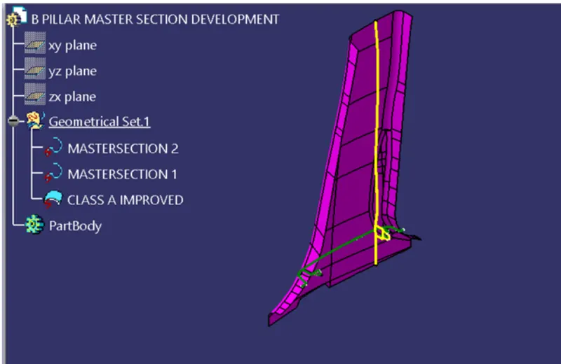
-The Body Frame Is Mainly Composed Of Floor Longitudinal Beams, Upper Side Beams, Door Sill Beams, And Front Cover, The Rear Beam, A-Pillar, B-Pillar, C-Pillar And Other Load-Bearing Beam Structures Are Composed.
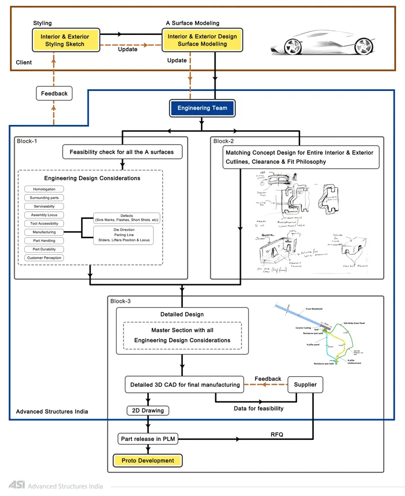
Master Sections Are Parameterized Model Of The Vehicle Body That Outlines The Guide For Npd Team
In This Report B Pillar Cover Creation With Detailed Procedures Of Surface Development And Attachement Features Are Covered.
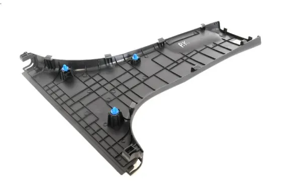
B-Pillar
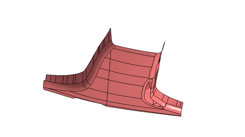
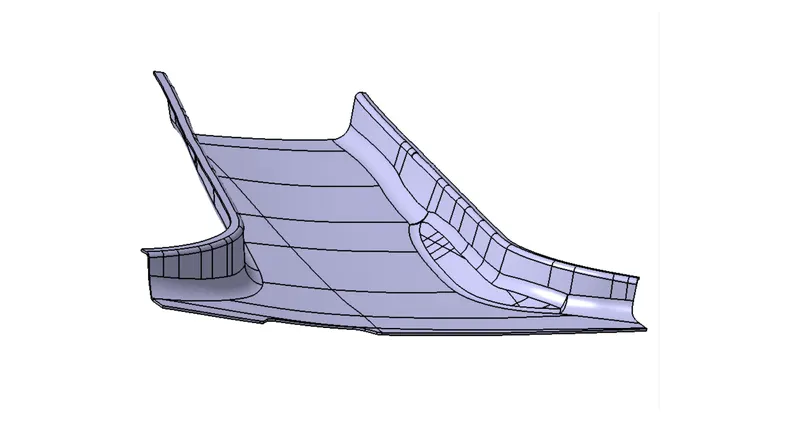
-A Surface Improvement.
Before We Start Creating The Closed Body For The B-Pillar We Need To Check The Quality Of The Given A-Surface. The A-Surface Needs To Be Free Of All The Patches Or Error Elements. For This First, We Need To Disassemble The Given Styling Surface And Join It With The Merging Distance Of 0.001mm.
Doghouse
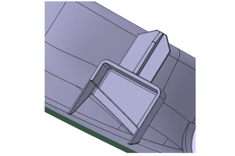
Using The Master Section The Doghouse Is Created And Then Part Modelled Using Thickness Option
-The 4 Way Locator Is Formed Above The Dog House Which Locates The B Pillar Towards The Mating Surfaces
-The Dog House Design Rules Are
-The Thickness Of The Connecting Surface Towards B Side Should Be 40% Off The Main Thickness
-The Walls Are Drafted With Min 0.5 Degrees Along The Main Tooling Direction
-The Attachement Feature Created Needs a Seperate Tooling Axis To Clear The Part Hence a Lifter Axis Is Used
Dog house
-Manufacturing Feasibility Of The A-Surface (Draft Analysis):
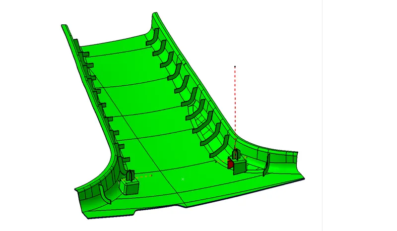
Draft Analysis Is Used To Check The A-Surface Manufacturing Feasibility. The Tooling Axis Is Used As a Reference. Draft Analysis Checks The Angle At Which The Surface Is With Respect To The Tooling Axis. As We Know For Injection Molding The Draft On The Surface Should Be Positive And Greater Or Equal To 3 Degrees. Areas With The Draft Less Than 3 Degrees Are a Bit Difficult And Costly To Manufacture.
Draft Analysis of B-Pillar
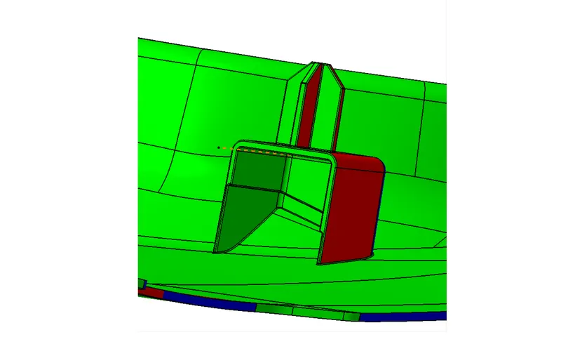
Draft Analysis of Dog house
-C Surface Creation
-The Next Step Is To From The C Surface Which Is An Intermediate Surface Between A And B And Is Used To Give The Closed Surface Appearance To The Design
-The C Surface Is Swept Using The Profile As Boundary Line Of Class A Which Is The Guide Curve With a Subtype Along Draft Direction.
-The Direction Of The Sweep Is The Tooling Direction Formed Earlier.
-The Draft Angle For The Sweep Operation Is Provided Which Is 3 Degree And Surface Is Swept For Length Above The Thickness Of The Specified Part .
-The C Surfaces Must Be Drafted Outwards From The A Side To Avoid The Parting Line Along The A Surface.
-The C Surface Is Refined Using Smooth Curve Options To Remove The Complexity And Patches Along The Swept Surface.
-Finally The Class A And Class C Surfaces Are Joined Together And Connexity Of Surfaces Should Be Less Than 0.003mm And The Surfaces Are Merged.
C Surface Merged With Class A
-Closed Body Creation
-The Merged Surface Is Then Trimmed With B Surface To Form The Closed Surface.
-The Closed Surface Is Then Validated To Find The Irregularities Along The Edges And Imperfections Along The Edges Were Then Corrected Using Operation Like Extrapolate And Surface Trim
-This Closed Surface Is The Outer Skin And Finally The Part Is Formed By Closed Surface In Part Design Workbench
-The Final Part Is Measured To Validate The Uniform Thickness Of The Part Especially Along The Filleted Edges.
-The Uniform Thickness Ensures That The Part Created Doesnt Form Sink Mark And Flow Lines Along Class A
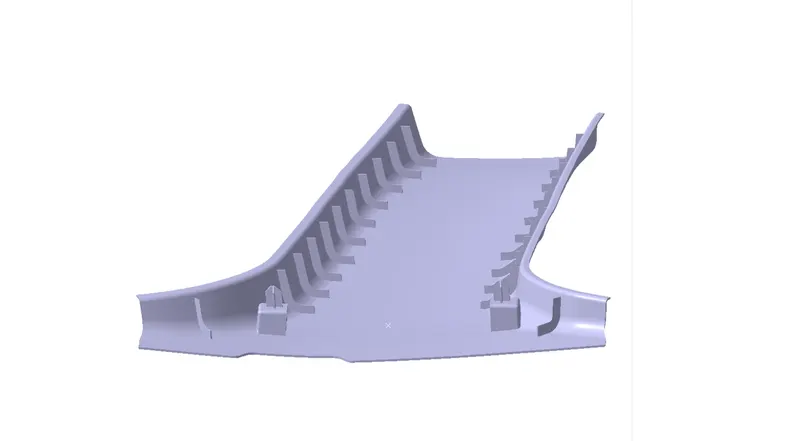
B-Pillar Final model
Result
-The Green Color Is Drafted Walls Above 3 Degree
-The Blue Color Is Drafted Walls From 0-3 Degree
-The Red Surfaces Are Negative Degree
-The Analysis Shows The Drafted Walls Are Above The Par Of 3 Degree Which Is Permissible To Manufacture In The Injection Modeling
-The Running Point Analysis Hovered Along The Drafted Walls Show Parts Are Above 3 And Will Be Easily Cleared From Ejection.
-The Areas In Negative Tooling That Falls Short To The Permisble Design Rules Are Shown
-These Surface Are Corrected Using Surface Operations And Generaly In Oem Class A Improvement Requires Prior Approval From Styling Team And The Draft Report And Analysis Is Used To Get Approval
-The Tree Structure Are Classified And The Important Features Are Published And The Operations Are Renamed And Classified Into Geometric Subset Shown Below.
Conclusion
Thus a Tooling Axis Is Created And a Open Aesthetic Class A Surface Is Developed Into a Closed Surface With All Plastic Design Rules And a Final Part Body Is Created Out Of It In Catia Surface Work Bench. The Design Is Then Validated With Master Section And Understood The Use Of Master Section Development In Product Design Through Development Of B Pillar Cover Used In The Car Interiors.