Week 11 - Final project
AIM: TO CREATE A CAD MODEL CONSIDERING CLASS A SURFACE , NOMINAL THICKNESS AND ATTACHMENT STRATEGY.
OBJECTIVE:
TO CREATION OF CAD MODEL CONSIDERING CLASS A SURFACE , NOMINAL THICKNESS AND ATTACHMENT STRATEGY.
Create thickened part using master section for refrence .
Create mounting features as per design guidelines in the industry and with the master sections.
Apply material details
Draft analysis & Tooling analysis.
PROCEDURE:
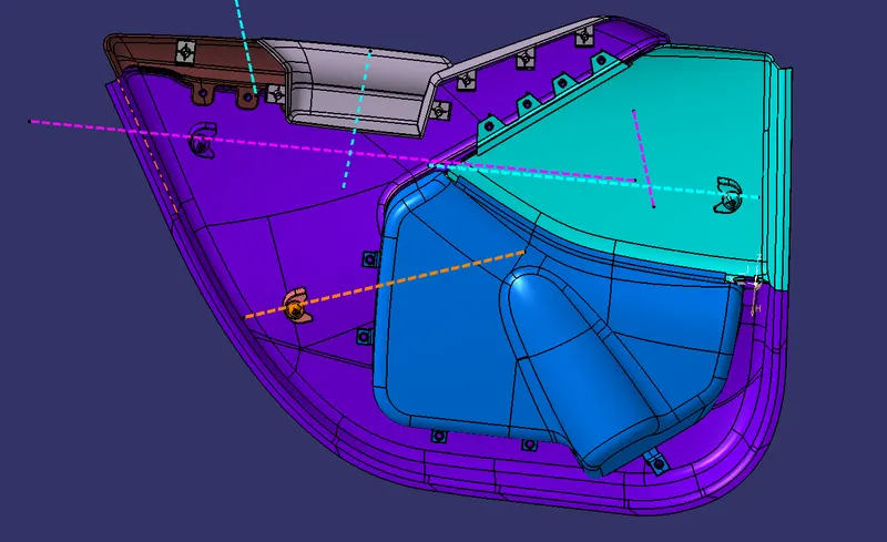
1. Import the file. File>open>browse file and select given file (MASTER_SECTION_DEVELOPMENT.igs) shown in the figure below:
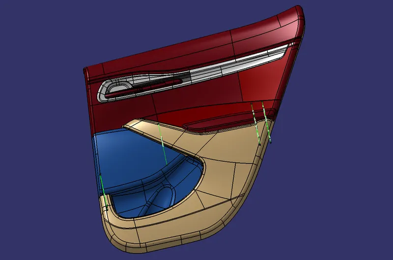
2.CLASS A surface modification as per master section:
From the given data we have to do cad model for lower substrate, Arm rest and map pocket
A.LOWER SUBSTRATE: Given lower substrate class A along with the master surface is shown below in fig
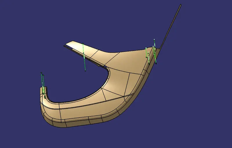
Find the tooling axis for the surface by performing draft analysis using draft analysis tool(Insert>analysis>draft analysis)
So we need to add surface to class A by using master section shown in below fig.
B. MAP POCKET : Given lower substrate class A along with master surface is shown in the fig:
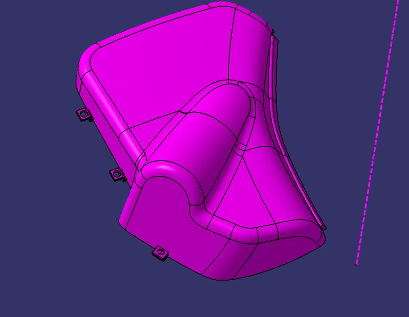
Map pocket is divided into two parts. Find the tooling axis for the surface by performing draft analysis using draft analysis using draft analysis tool (insert>analysis>draft analysis) for two parts.
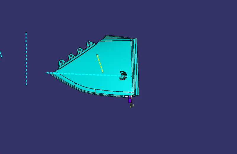
2.Class B surface: For all parts class B surface is created by direct offset and extrapolated
So we need to add surfaces to class A by using master section shown in fig:
C. ARM REST: Given lower substrate class A along with master surface is shown in fig:
we Find the tooling axis for the surface by performing draft analysis using draft analysis using draft analysis tool (insert>analysis>draft analysis) for two parts.
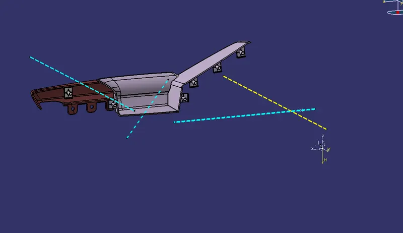
So we need to add surfaces to class A by using master section shown in fig:
2.Class B surface: For all parts class B surface is created by direct offset and extrapolated.
3. Class c surface : Class C surface are created using tooling direction as well as surface reference.
tools used:
- creating swept surfaces: The swap tool is provided to create surface by sweeping a profile along a guide curve in the wireframe and surface design workbench of CATIA V5 .
- Creating swept surface with draft direction: similar to the creating swept surface but we have to select direction for the draft
- Creating lofted multisection surface: This tool allows you to lofted multisection surfaces. The surface is created between the section along the computed or user defined spine. To create a multisection, first we need to create section and guide curves.
4.Final trimming: Trimming class A , with class C and Class A+C with class B .Using trimming surface Insert >operation >Trim .