Advanced Sheet Metal Design Using NX Cad Challenge_6_Bracket
SHEET METAL DESIGN OF BRACKET IN NX-CAD
OBJECTIVE:
To design and model the sheet metal bracket from a 2D Sketch in sheet metal workbench of Siemens NX CAD.
INTRODUCTION:
Sheet Metal Fabrication is the process of forming parts from a metal sheet by punching, cutting, stamping, and bending.
Sheet metal parts are known for their durability, which makes them great for end-use applications (e.g., chassis). Parts used for low volume prototypes and high-volume production runs are most cost-effective due to large initial setup and material costs.
In Sheetmetal application we can create a uniform thickness Sheetmetal parts using basic features such as flange, tabs and jogs. We can also do close corners, cut out and stiffening features. The complex sheet metal part can be designed in the solid model workbench and then we can convert it into a sheet metal part. We can also import, clean up and convert a non-sheet metal part into a valid sheet metal part. Flat pattern sheet metal data can be used for the manufacturing process. The Material parameters such as thickness, bend radii and bend relief can be easily set as default settings.
Design methodology:
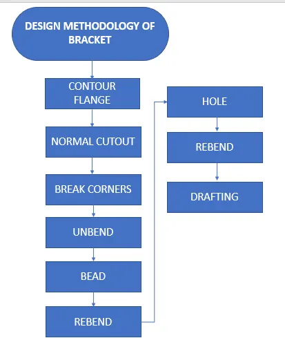
TOOLS AND FEATURES USED ON SHEETMETAL TO DESIGN BOX ASSEMBLY:
- Sketch
- Normal Cutout
- Contour Flange
- Break corner
- Unbend
- Hole
- Bead
- Re bend
- Drafting
- Base view
TOOL AND FEATURE DESCRIPTION:
- SKETCH
It is a 2d representation of a 3d part. It includes entities like line, rectangle, spline, circle,etc. It is a predetermined drawing with dimensions and relations.
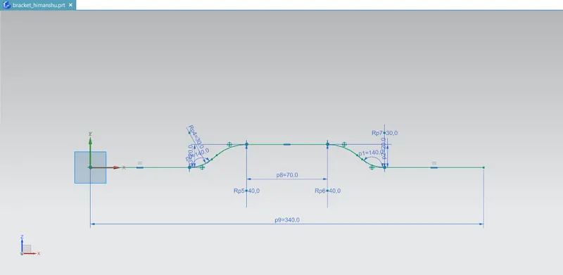
- CONTOUR FLANGE
It is created with one or more edges at specified location. The minimum flange length must be at least four times the thickness of the sheet metal. Bend radius is equal to the sheet metal thickness.
- NORMAL CUTOUT
This command is to remove the desired shape of material. Removal sketch can be drawn on the sheet metal face, wherever required.
- BREAK CORNER
This command gives a smooth finish over the corners of the sheet metal part.
- UNBEND
It makes the part unbend, that is all the features done are made flat. This is useful while sketching on the corners and bend areas.
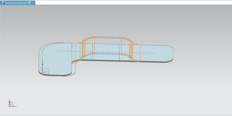
- BEAD
It lifts material along contour sketch.
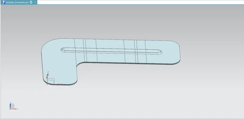
- REBEND
This command puts back all the bends already created also along with new features included while in unbent state.
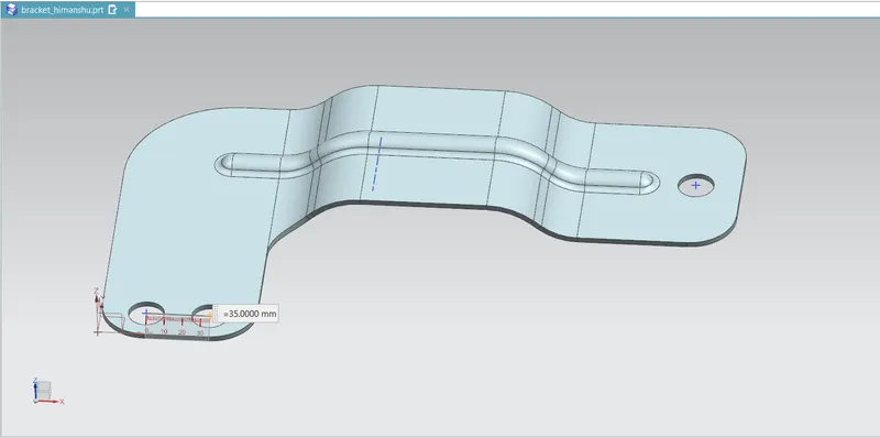
- DRAFTING
This command is to have 2D drawing of the sheet metal part created. It is refers to creating technical drawing that communicate about dimensions, view of component geometry and other features that performed over part in 2D or 3D. The draft of drawing is prepared which include annotation, dimension, relations, etc. which helps to a person from manufacturing or production department about component.
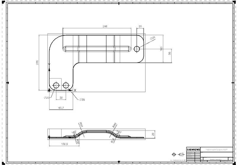
- BASE VIEW
It specifies the location, orientation, view and scale of the part for drafting.
BRACKET STANDARD VIEWS
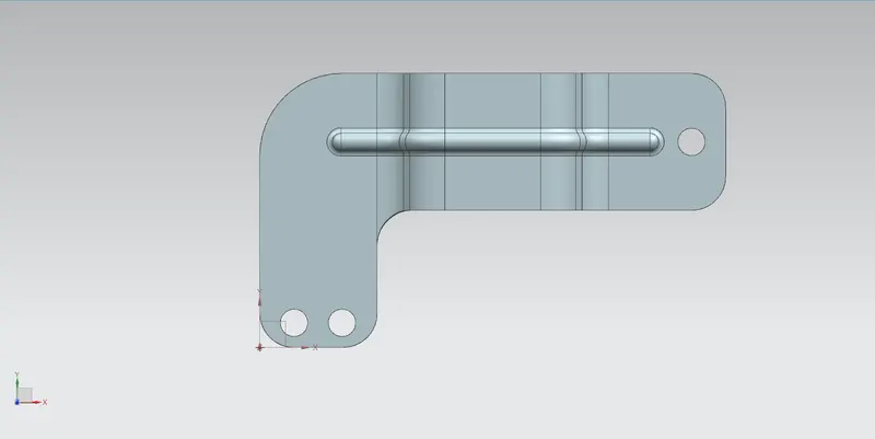
TOP VIEW:
Right side view:
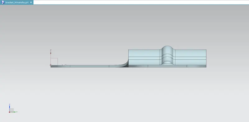
Side view:
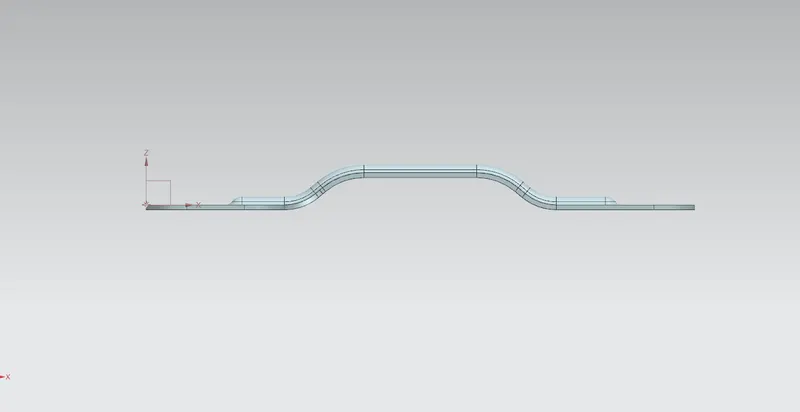
Isometric view:
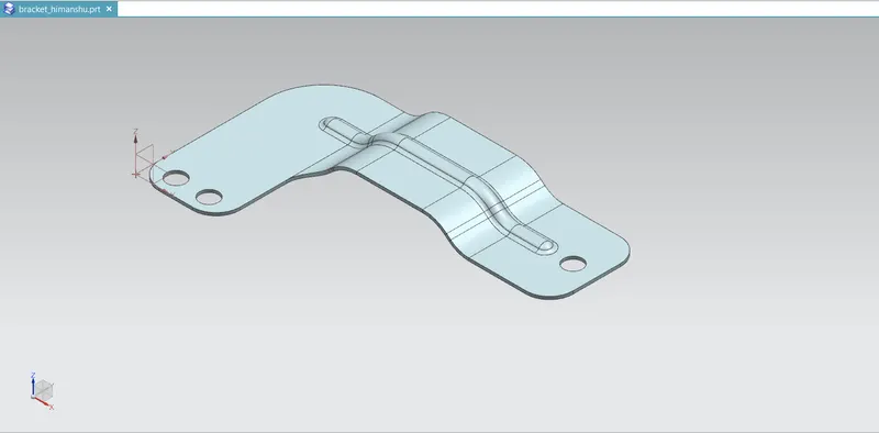
CONCLUSION:
The sheet metal Recommended workflow to create Bracket Component or angles is successfully completed in NX Cad.