Frequency Analysis of a rotating shaft
FREQUENCY ANALYSIS OF ROTATING SHAFT
OBJECTIVE:
- To carry out the frequency analysis of a rotating shaft.
- To determine its natural frequency and corresponding mode shapes.
INTRODUCTION:
- Frequency analysis is performed to find out the natural frequency and corresponding mode shapes of the component.
- The natural frequency is the frequency with which component will vibrate if disturbed and allowed to vibrate on its own without any external force acting on it.
- Mode shapes of the component give the direction in which component is vibrating at that corresponding natural frequency.
- Damping effects are neglected in frequency analysis when finding the 'Natural frequency' of the component.
- Components will have an infinite number of natural frequencies but the lowest natural frequency is known as the fundamental frequency.
- Natural frequency is determined to avoid the resonance of the component.
- Resonance occurs when the external frequency is equal to the natural frequency, in this state resonance amplitude causes the failure of the component.
MODELING:
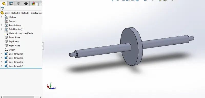
- The 3D model of the shaft is part modeled in Solidworks, according to the proportionate dimensions so as to fit the looks of the shaft in the problem definition.
- The first sketch is created and the sketch is rotated about an axis to create a shaft.
- All dimensions are in 'mm' only.
FREQUENCY ANALYSIS:
- Frequency analysis is selected for simulation.
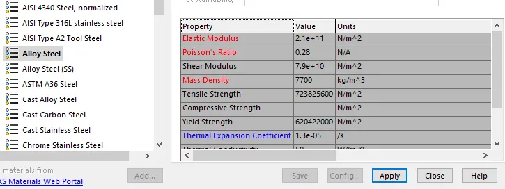
- Alloy steel is the material applied to the shaft.
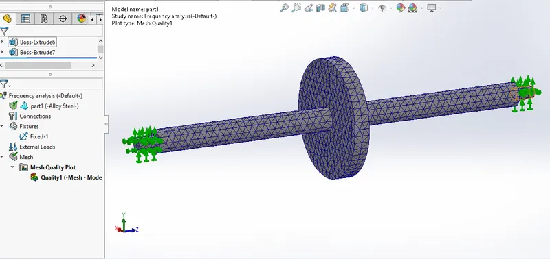
- Bearing fixture is applied on the stepped surface of the shaft on both sides, it indicates that fixtures support the shaft to rotate about its own axis.
- Default Mesh is applied, and simulation is solved for the results.
RESULTS:
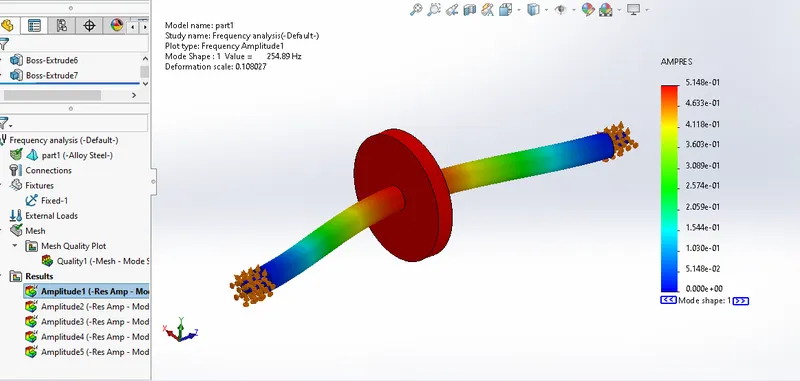
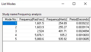
- In simulation results,5 natural frequency corresponding 5 mode shapes are obtained.
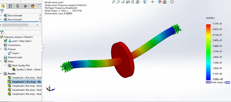
1st & 2nd mode
- Both modes have the almost same natural frequency of 255 Hertz but the only difference is mode 1 oscillates in 'z' direction and mode 2 oscillates in 'y' direction.
- It can be seen when you animate the results.
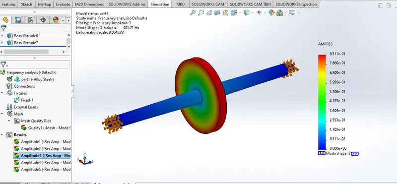
3rd mode
- This mode is mechanism mode, this component has one rotational degree of freedom about its axis, hence the 3rd mode of natural frequency analysis is shown as a rigid mode.
- Hence, this first mode has a natural frequency of 401.71 hertz.
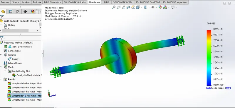
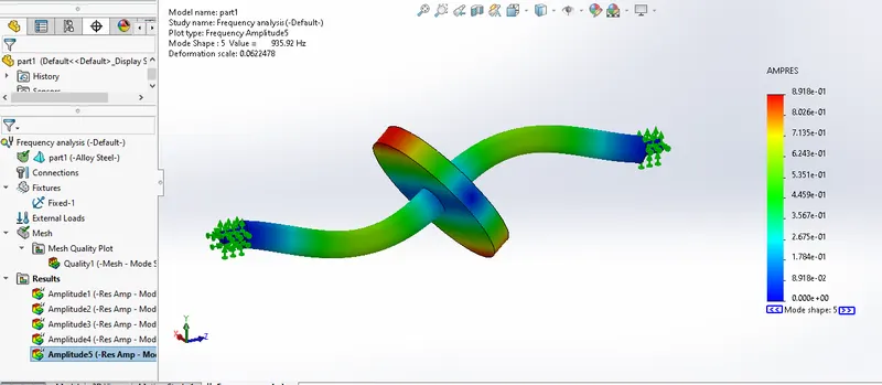
4th and 5th mode
- Both modes have the same natural frequency of almost 935 hertz but the only difference is mode 4 oscillates about 'y' axis and mode 5 oscillates about 'z' axis.
- It can be seen when you animate the results.
Frequency table for different modes:
Conclusion:
- In conclusion, mode shapes and natural frequency values give the direction in which external excitation frequency should be applied and the allowable excitation frequency can be applied.
- But, generally, external excitation frequency cannot be controlled, So we need to alter the natural frequency of the component itself by varying its mass and stiffness.