Project 2
Aim: Perform meshing on the Floor panel geometry of a car using Hypermesh.
About the geometry: Floor panel is made up of sheet metal of uniform thickness. Its thickness is about 0.75mm but at some of its boundary its thickness slightly varies to 0.87 we can considered it as uniform.
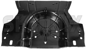
Fig 1. Floor panel
Procedure:
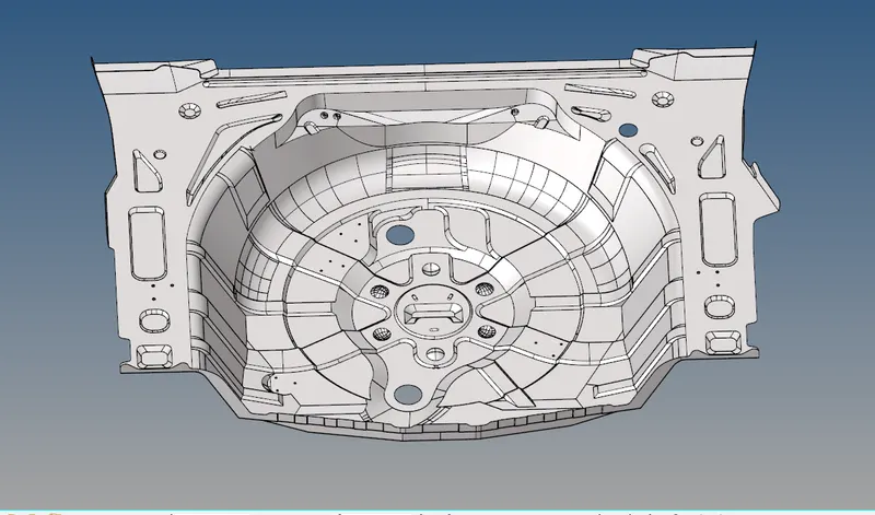
Import the .hm file.
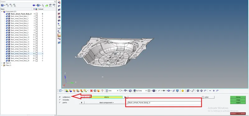
Organise all the components to collector using Tool>organise>collector.
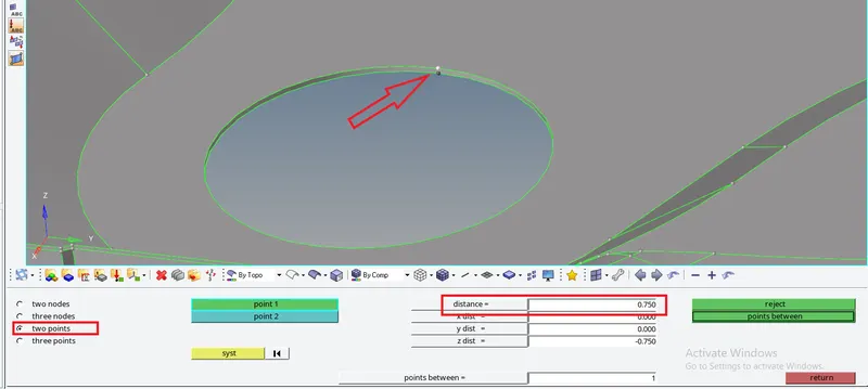
Measure the distance between the surfaces using Geom>distance.
Extract the manual mid surface using Geom>surface edit >offset. Select the surface by face put the offset value as 0.375.

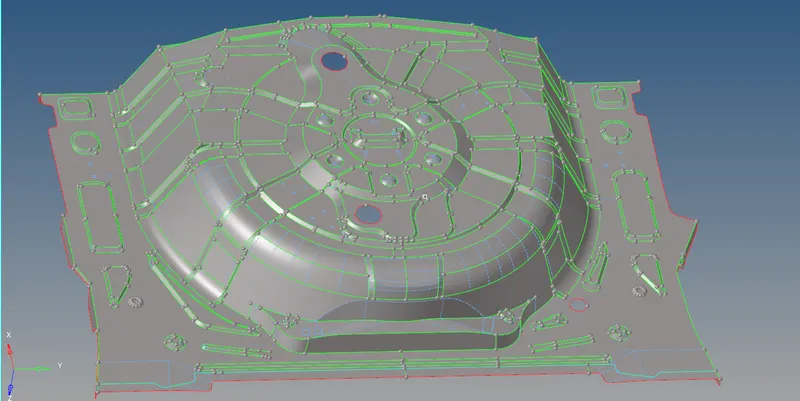
Clearout the errors on the midsurface obtained using quick edit panel. Remove small buttons on side part and toggle line which are of distance less than 2mm. Toggle lines which are not the part of features.
why do we extract mid-surface?
Mid surface is a surface between two surfaces.If we mesh the entire component in 3D the number of nodes and elements will increase which in turn would increase the storage space and processing power to analyze the components. To avoid this mid surface is created where we represent the entire 3D model by mid surface and create shell elements.
Meshing
Why do we perform meshing?
The basic idea of FEA is to make calculations at only limited (Finite) number of points and then interpolate the results for the entire domain (surface or volume). Any continuous object has infinite degrees of freedom and it’s just not possible to solve the problem in this format. Finite Element Method reduces the degrees of freedom from infinite to finite with the help of discretization or meshing (nodes and elements). One of the purposes of meshing is to actually make the problem solvable using Finite Element. By meshing, you break up the domain into pieces, each piece representing an element. You need these elements to be able to apply Finite Element since Finite Element is all about having a basis local to an Element and stitching a bunch of local solutions together to build the global one. If you did not mesh and just assumed some basis that covered the whole domain that would be a Spectral Method. One other aspect of meshing is the accuracy of your solution. It can be shown that your global solution accuracy is a function of element width and the smallest angle at some element’s vertices. Due to these contributors to accuracy, it's important to be careful about how you implement your mesh to ensure angles within elements are larger (smaller angles hurts accuracy) and that you get it sufficiently refined to get the accuracy you wish.
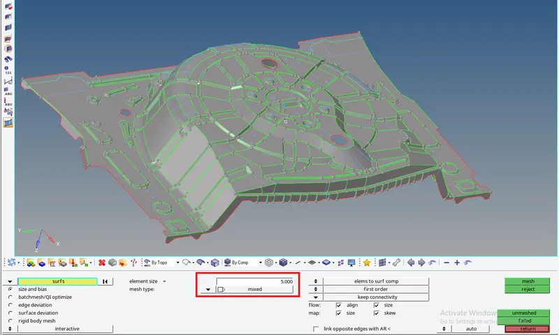
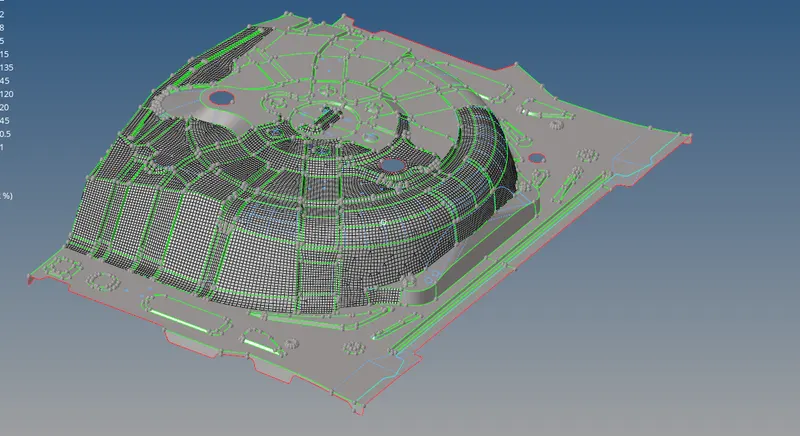
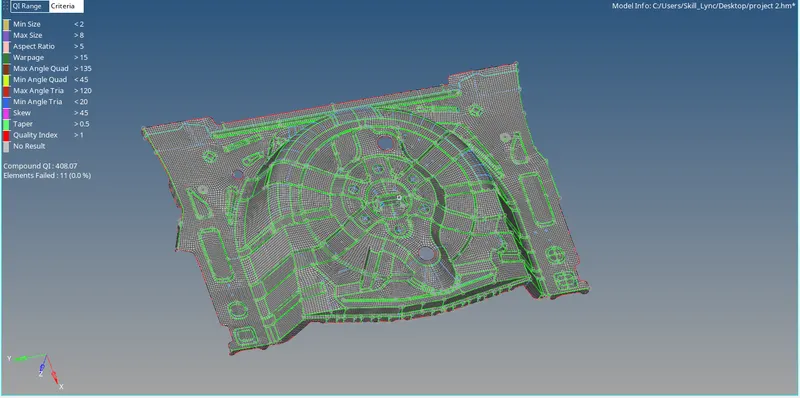
Meshing is performed using 2D>automesh. Select element size as 5mm and mesh type as mixed type.
Quality criteria
These are the parameter or the ranges upto which the ideal geometry or mesh size can be compromised or altered.
Following quality criteria needs to be followed.
Target Element Length = 5mm
| S.N | Quality Criteria | Value |
| 1 | Aspect Ratio | 5 |
| 2 | Skewness | 45 |
| 3 | Warping | 15 |
| 4 | Taper | 0.5 |
| 5 | Min. Length | 2mm |
| 6 | Max. Length | 8mm |
| 7 | Min angle Quad | 45 |
| 8 | Max angle Quad | 135 |
| 9 | Min angle Tria | 20 |
| 10 | Max angle Tria | 120 |
| 10 | Tria % | 10 |
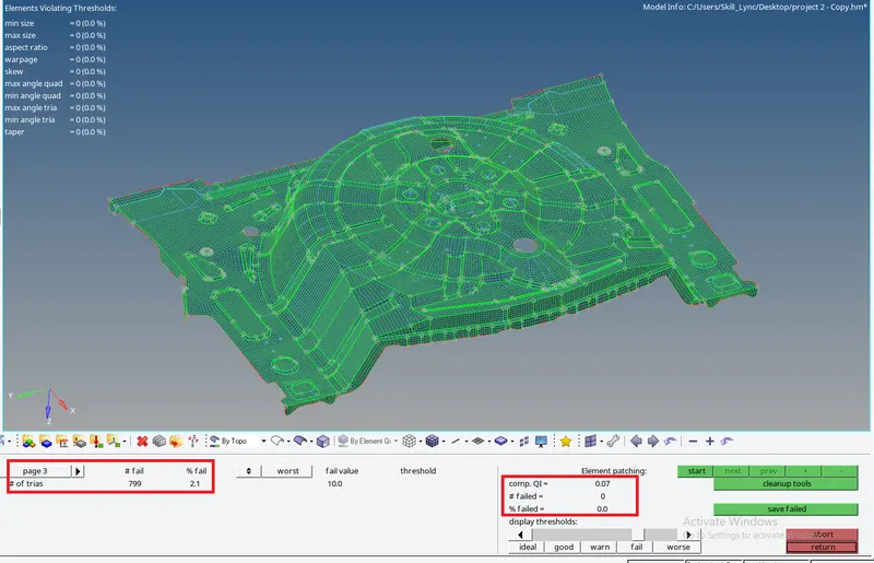
There will be many areas where which will not follow quality criteria
We will try to fix these areas using following tools:
Swap edge,Smooth,Drag tria element, node optimize,split, quad element combine ,tria elements.
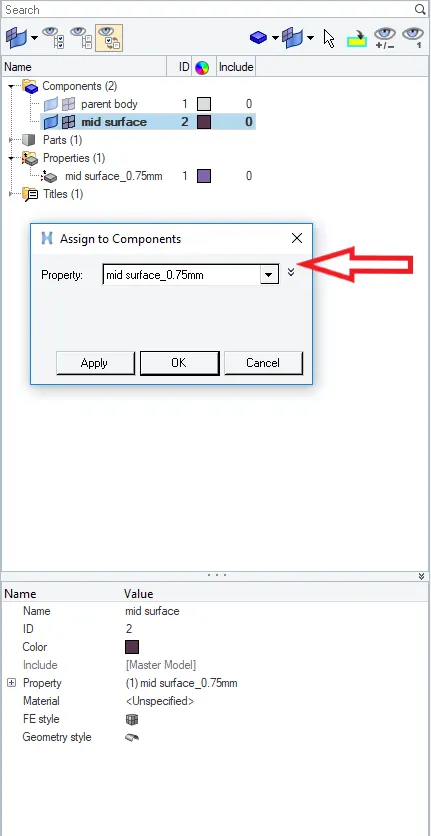
Assign thickness and property card to the component.
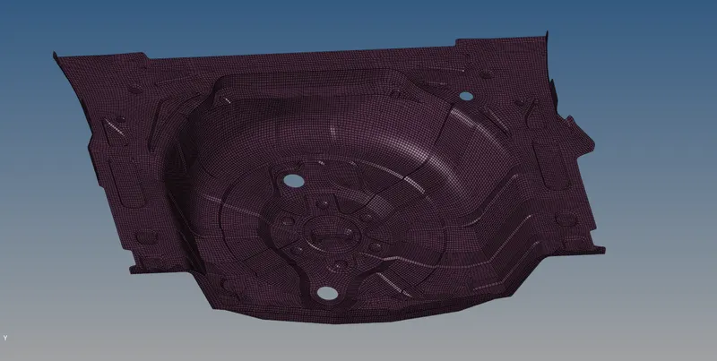
Below is cleaned meshed thickened surface.
We can check for normals by go into tool>normals. Select Displayed 2D elems and clicked on display.
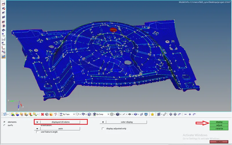
As we can see in above image that all the elements of upper surface is in blue color it means force acting on these elements are downwards (in same direction).
Learning outcomes
- Learned to extract mid surface.
- Learned assigning thickness and properties
- Learned to clean the model using various tools under quality index.
Conclusion
In the project the manual mid surfacing,meshing and thickness assigning of floor panel of car is successfully performed.