Photo Realistic Rendering
MODELING AND RENDERING OF AMERICAN CHOPPER
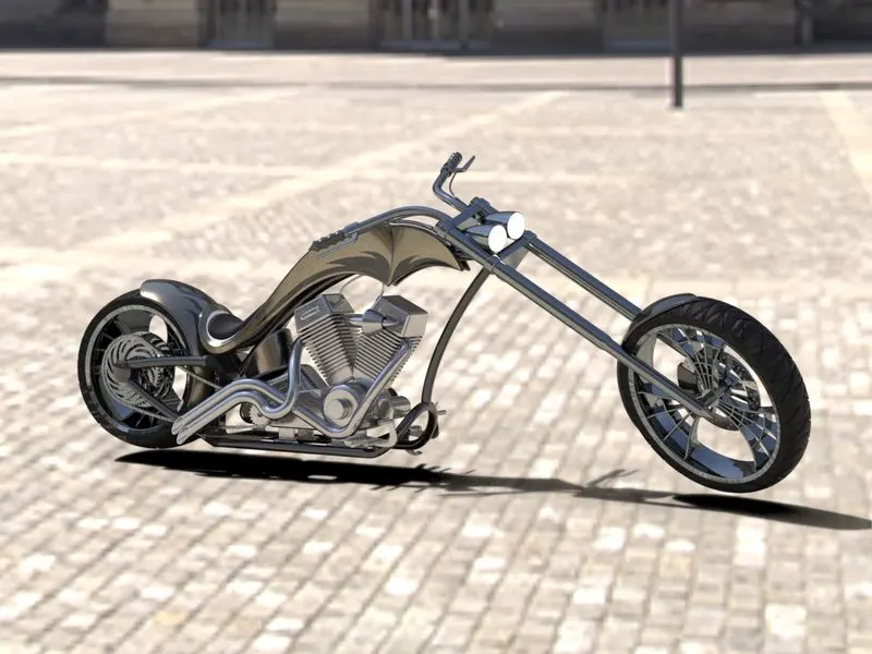
AIM & OBJECTIVE: To model an American Chopper using Solidworks and render it to create a photorealistic view.
INTRODUCTION: This project explains the designing and modeling of American Chopper parts and how the assembly of these individual parts are done to get the final product with realistic views using rendering.
METHODOLOGY:
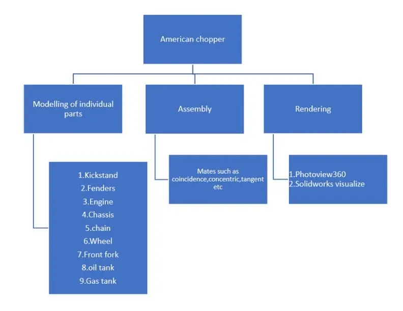
The above flow chart is followed for the modeling of the American Chopper.
* Individual Part Modelling are considered the first step to begin our project.
* Secondly, mates are applied in between the individual parts to form Assembly.
* Thirdly, adding decals to the assembly.
* Lastly, rendering is done to obtain the realistic views of the American Chopper.
DESCRIPTION:
# Commands used to design the components:
* Line: Feature allows us to create a straight line (either solid or constructed).
* Circle: Feature allows creating a circle.
* Arc: For creating Arcs.
* Rectangle: For creating squares and rectangles.
* Ellipse: For creating elliptical shapes.
* Spline: For creating curved lines.
* Offset Entities: To offset an object by a specified distance.
* Curved Projection: For projecting Curves made in different planes to create an intersected curve.
* Split: For splitting bodies using 2D sketch.
* Trim: For trimming out the extra objects from the sketch.
* Extend: For extending the objects up to the next object.
* Extrude Boss: For creating Solid bodies.
* Extrude Cut: For removing portion as per sketch from solid bodies.
* Swept Boss: Sweep creates a base, boss, cut, or surface by moving a profile (section) along a path.
* Mirror: For creating an exact copy of the body using a reference plane or face.
* Revolve: Add or remove material by revolving one or more profiles around a centerline.
* Linear Pattern: For creating pattern in a straight line.
* Circular pattern: For creating pattern in a circular path.
* Fillet: To round the edges of the sketch or part.
* Chamfer: To create inclined edges.
* Plane: New reference planes are created for simplifying the modeling procedures of the components.
* Loft: Creates a feature by making transitions between profiles.
* Dome: Allows to create a dome shape on one or more faces on the same model.
* Shell: It is used in defining the thickness of thin shell elements.
* Convert Entities: To create one or more curves on sketch by projecting an edge, loop, face, curve, or external sketch contour, set of edges, or set of sketch curves onto the sketch plane.
* Surface Trim: We can use a surface, plane, or sketch to trim intersecting surfaces. We can also use a surface in conjunction with additional surfaces, as mutual trim tools.
* Surface Knit: Used to combine 2 or more faces and surfaces into one.
* Combine Tool: In a multi body part, we can combine solid bodies to create a single bodied part. Similarly, We can also subtract bodies or keep the material that is common to the selected bodies.
# Components of the American Chopper:
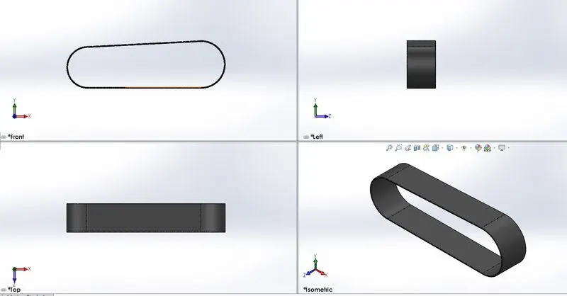
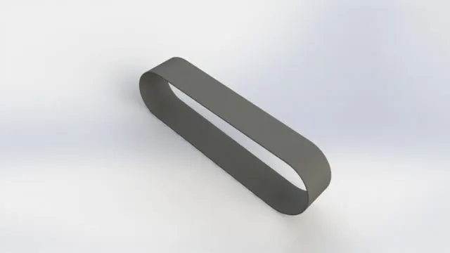
1. Transmission Belt:
Features used: Extrude base and fillet.
Sketch Tool: Line, arc and offset Entities.
Appearance: Matte Rubber.
Views:
Rendered Image:
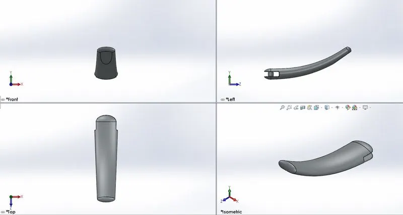
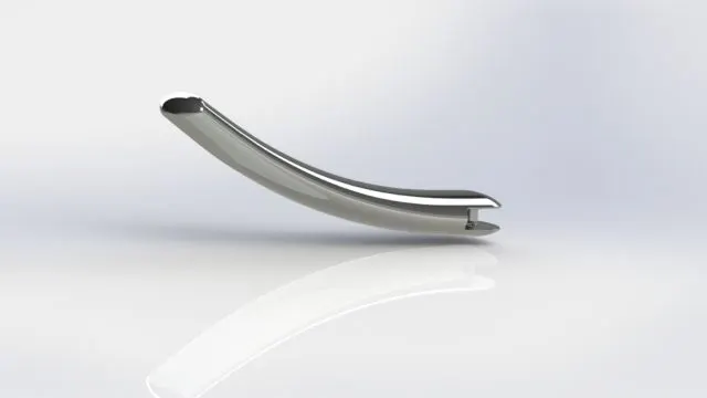
2. Kickstand:
Features used: Extrude base, Loft base, Extrude Cut and Pierce.
Sketch Tool: Rectangle, Circle, Spline and Ellipse.
Appearance: Chrome Steel.
Views:
Rendered Image:
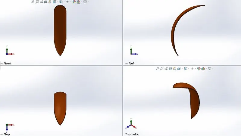
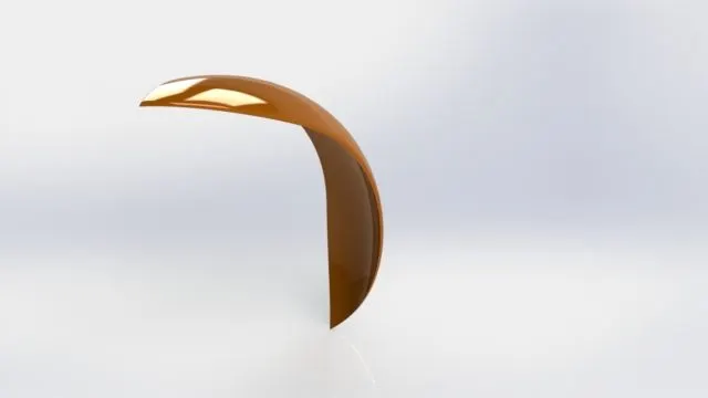
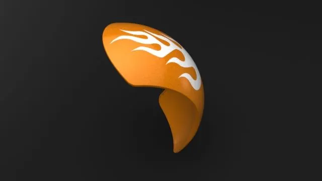
3. Front Fender:
Features used: Revolve base, fillet, and Split.
Sketch Tool: Spline, Three-point Arc, and Line.
Appearance: Painted Siena.
Views:
Rendered Image:
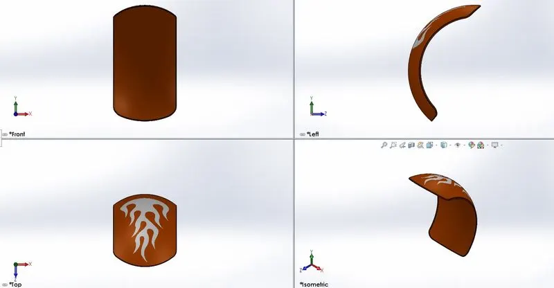
4. Rear Fender:
Features used: Revolve base, fillet, Shell and Split.
Sketch Tool: Spline, Three-point Arc, Offset Entities and Line.
Appearance: Painted Siena.
Views:
Rendered Image:
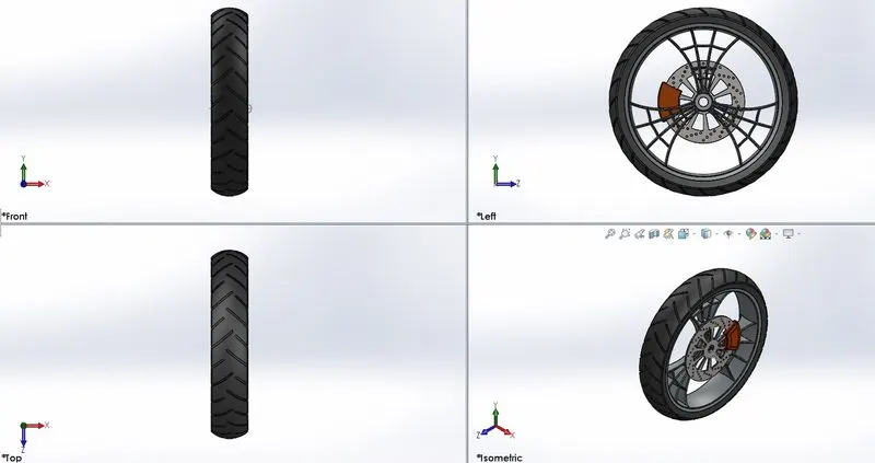
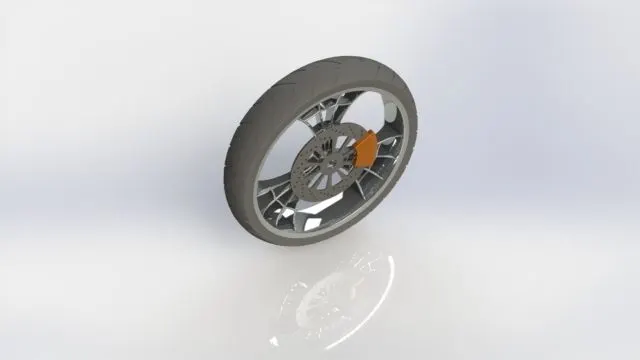
5. Front Wheel:
Features used: Revolve base, fillet, Chamfer, Extrude Base, Revolve cut, Circular pattern, Linear pattern and Mirror.
Sketch Tool: Spline, Three-point Arc, Offset Entities, Convert Entities, Trim, Rectangle, Circle and Line.
Appearance: Painted Siena for caliper, Chrome Steel for Rim, Matte Rubber for Tire.
Views:
Rendered Image:
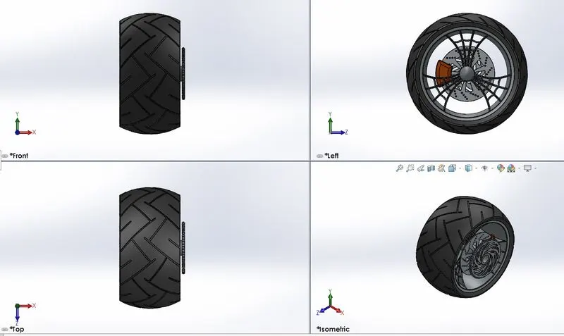
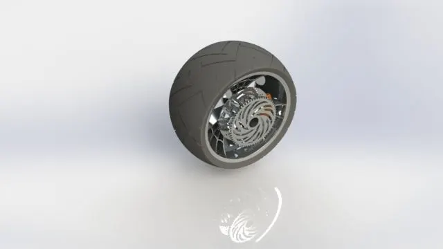
6. Rear Wheel:
Features used: Revolve base, fillet, Chamfer, Extrude Base, Revolve cut, Circular pattern, Linear pattern and Mirror.
Sketch Tool: Spline, Three-point Arc, Offset Entities, Convert Entities, Trim, Rectangle, Circle and Line.
Appearance: Painted Siena for caliper, Chrome Steel for Rim, Matte Rubber for Tire.
Views:
Rendered Image:
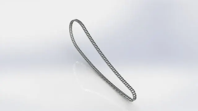
7. Chain link:
Features used: Fillet, Extrude Base, Block, Delete/Keep body, curve driven and Mirror.
Sketch Tool: Straight Slots, Three-point Arc, Convert Entities, Trim, Circle and Line.
Appearance: Chrome Steel.
Views:
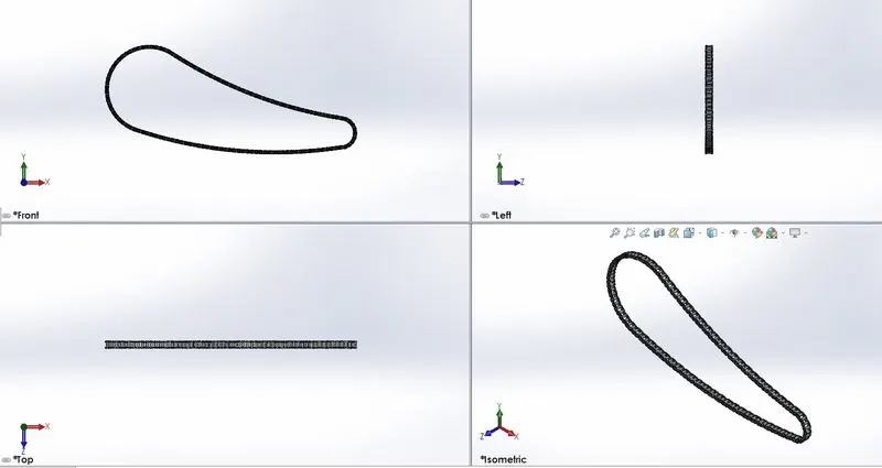
Rendered Image:
8. Oil Tank:
Features used: Fillet, Extrude Base, Shell and Combine.
Sketch Tool: Spline, Circle and Line.
Appearance: Painted Siena.
Views:
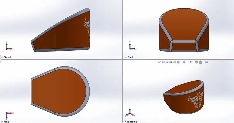
Rendered Image:
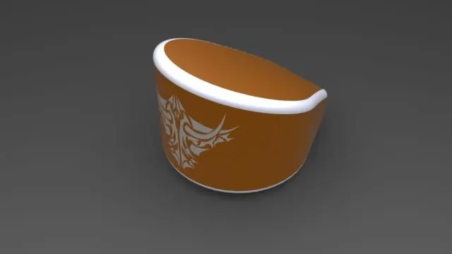
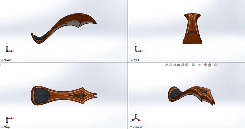
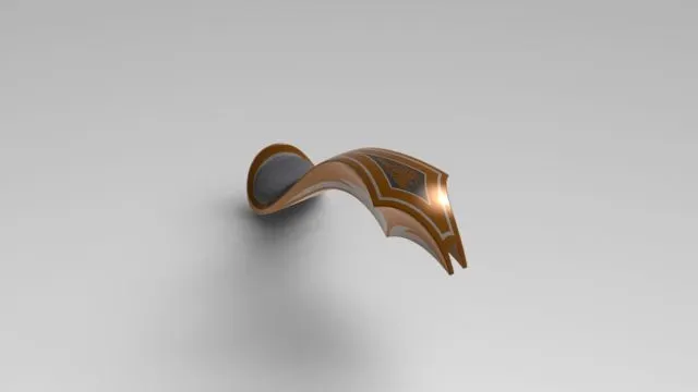
9. Gas Tank:
Features used: Fillet, Swept Surface, Combine, Projected Curve, Mirror, Surface Knit, Swept Shell and Boundary Surface.
Sketch Tool: Spline, Circle, Convert Entities, Offset, and Line.
Appearance: Painted Siena for Gas Tank and Fabric for Driver Seat.
Views:
Rendered Image:
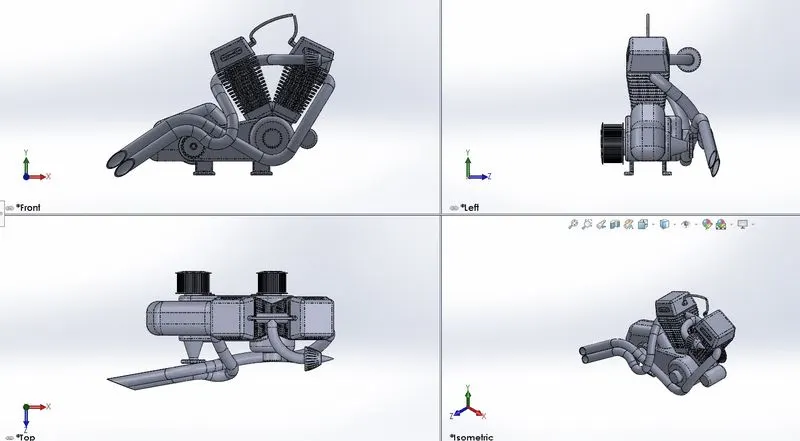
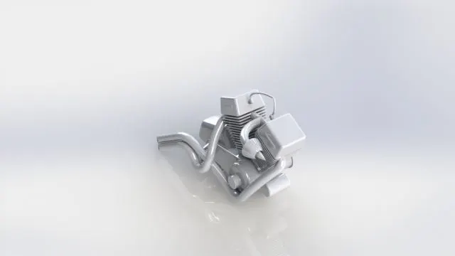
10. Engine:
Features used: Fillet, Extrude base, Dome, Extrude Cut, Revolved Cut, Composite Curves, Projected Curves, Swept Boss, Revolve Base, Chamfer, Fillet, Mirror and Combine.
Sketch Tool: Spline, Circle, 3 point Arc, Convert Entities, Offset, and Line.
Appearance: Chrome Plate.
Views:
Rendered Image:
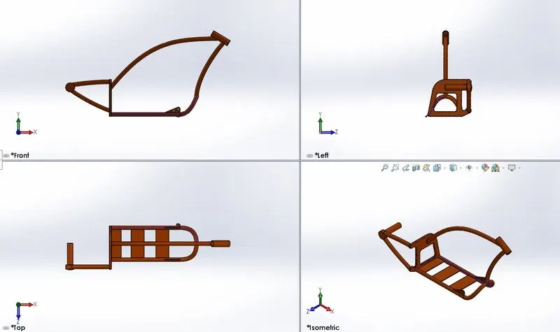
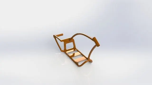
11. Chassis:
Features used: Split, Plane, Fillet, Extrude Boss, Dome, Extrude Cut, Revolved Cut, Composite Curves, Projected Curves, Swept Boss, Revolve boss, Chamfer, Mirror and Combine.
Sketch Tool: Spline, 3 point Arc, Circle, Convert Entities, Offset, and Line.
Appearance: Painted Siena.
Views:
Rendered Image:
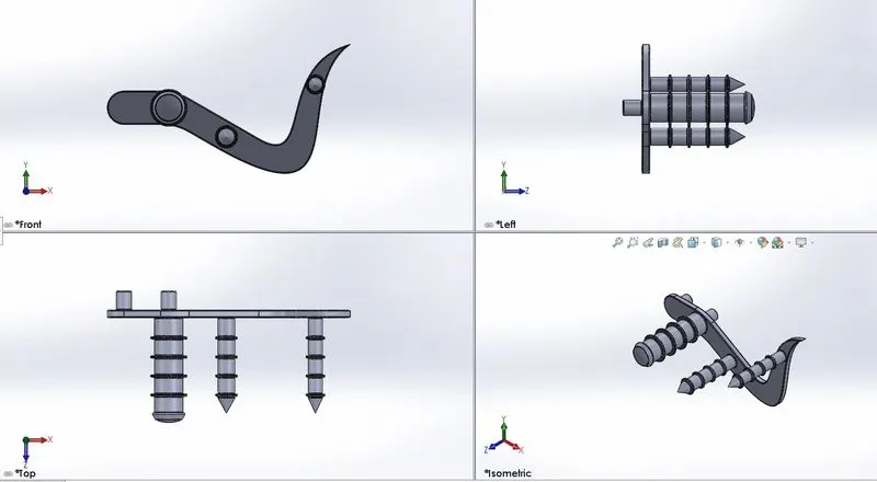
12. Pedal:
Features used: Fillet, Revolve Base, Extrude Boss, Dome, Linear Pattern and chamfer.
Sketch Tool: Spline, Circle, and Line.
Appearance: Chrome Plate.
Views:
Rendered Image:
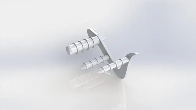
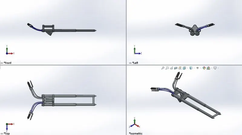
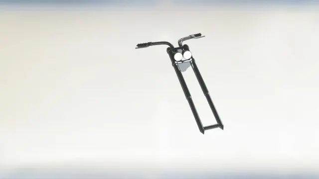
13. Front Fork:
Features used: Fillet, Plane Revolve Base, Extrude Boss and Cut, Revolve Cut, Composite Curves, Projected Curves, Swept Boss, mirror, combine and chamfer.
Sketch Tool: Spline, 3 point arc, Circle, offset and Line.
Appearance: Chrome Plate for fork, Matte Rubber for handle and brake wire, and for Arial Light and Lamp.
Views:
Rendered Image:
ASSEMBLY OF AMERICAN CHOPPER:
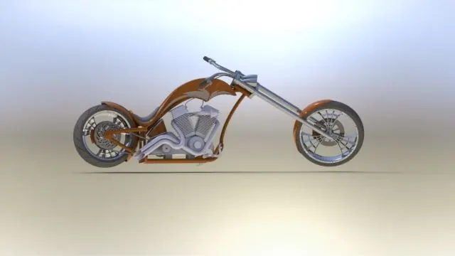
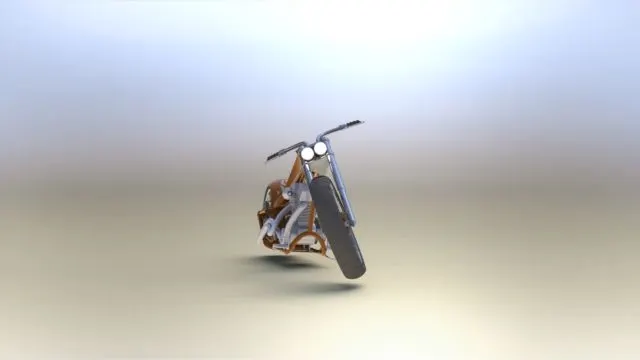
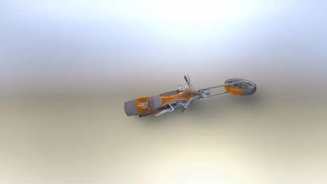
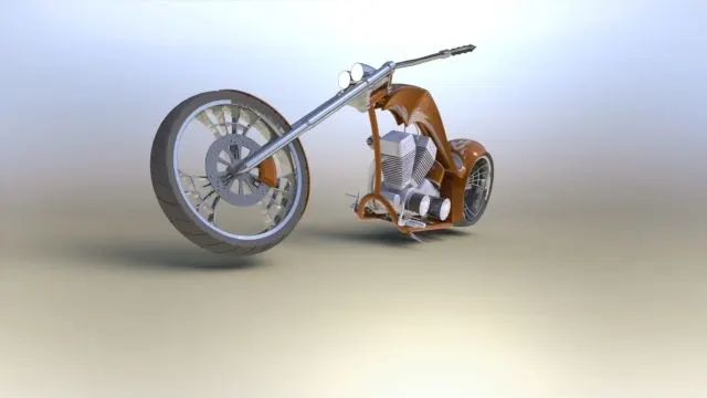
* All the parts are inserted into the assembly file with chassis as reference for all the other parts.
* Apply mates to individual parts with another with proper alignments.
# Front View:
# Side View:
# Top View:
# Camera 1 View:
# Isometric View:
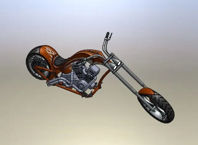
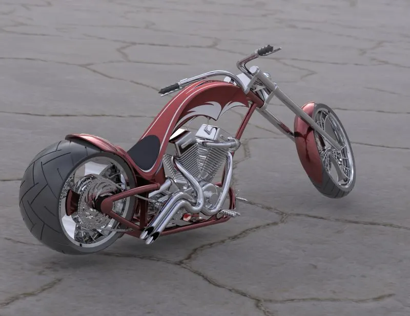
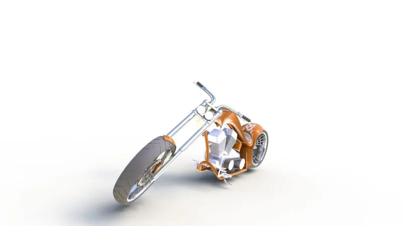
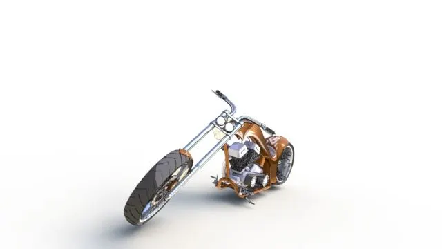
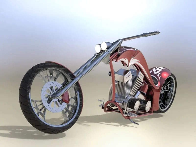
RENDERED on Solidworks Visualize 2022:
CONCLUSION:
Thus, the parts of the American Chopper are modeled, assembled using solidworks and are rendered using photoview 360 and solidworks visualize.
REFERENCES:
Drive Link for Assembly and Render files:
https://drive.google.com/drive/folders/18bUX1YZ_jvFRJuoOpKuBVibbOvUcZoPx?usp=sharing