Section Modulus calculation and optimization
AIM/ OBJECTIVE: Use the Section from your Hood design and calculate the Section Modulus and Come up with a new section that has an improved Section Modulus compared to the previous one, and mention what changes you made which resulted in the increased strength.
THEORY:
-Section Modulus: Section modulus is a geometric property for a given cross-section used in the design of beams or flexural members. Other geometric properties used in design include area for tension and shear, radius of gyration for compression, and second moment of area and polar second moment of area for stiffness. Any relationship between these properties is highly dependent on the shape in question. Equations for the section moduli of common shapes are given below. There are two types of section moduli, the elastic section modulus and the plastic section modulus. The section moduli of different profiles can also be found as numerical values for common profiles in tables listing properties of such.
-Notation: North American and British/Australian convention reverse the usage of S & Z. Elastic modulus is S in North America, but Z in Britain/Australia, and vice versa for the plastic modulus. Eurocode 3 (EN 1993 - Steel Design) resolves this by using W for both, but distinguishes between them by the use of subscripts - Wel and Wpl.
-Elastic Section Modulus: For general design, the elastic section modulus is used, applicable up to the yield point for most metals and other common materials.
The elastic section modulus is defined as S = I / y, where I is the second moment of area (or area moment of inertia, not to be confused with moment of inertia) and y is the distance from the neutral axis to any given fiber. It is often reported using y = c, where c is the distance from the neutral axis to the most extreme fiber, as seen in the table below. It is also often used to determine the yield moment (My) such that My = S ⋅ σy, where σy is the yield strength of the material.
Section modulus equation of general cross-sectional shapes are given below:
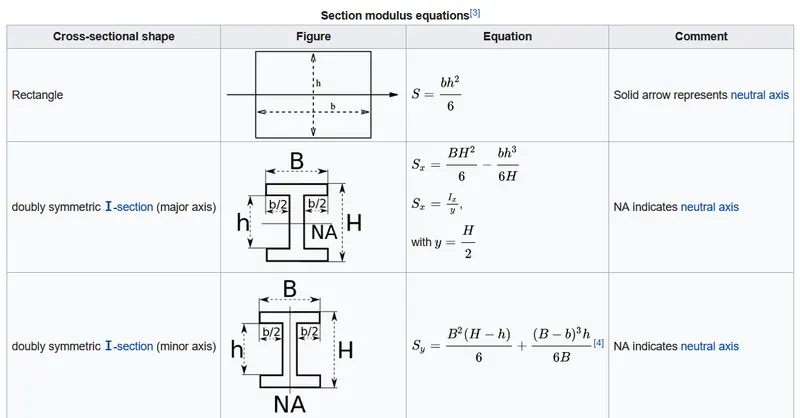
-Plastic Elastic Modulus: The plastic section modulus is used for materials where elastic yielding is acceptable and plastic behavior is assumed to be an acceptable limit. Designs generally strive to ultimately remain below the plastic limit to avoid permanent deformations, often comparing the plastic capacity against amplified forces or stresses.
The plastic section modulus is the sum of the areas of the cross-section on each side of the PNA (which may or may not be equal) multiplied by the distance from the local centroids of the two areas to the PNA:
Z P = A C y C + A T y T 
The Plastic Section Modulus is not the 'First moment of area'. Both relate to the calculation of the centroid, but Plastic Section Modulus is the Sum of all areas on both sides of PNA (Plastic Neutral Axis) and multiplied with the distances from the centroid of the corresponding areas to the centroid of the cross-section, while the First moment of area is calculated based on either side of the "considering point" of the cross-section, and it is different along the cross section and depends on the point of consideration.
-Moment of Inertia: Moment of inertia is defined as the quantity expressed by the body resisting angular acceleration which is the sum of the product of the mass of every particle with its square of a distance from the axis of rotation.
the minimum moment of inertia value is considered for the Section modulus calculation. Because, the minimum inertia value is the most susceptible for easy breaking of the Hood part. 'Y' distance is with respect to one end of the curve to the center axis of the intersection curve.
CALCULATIONS:
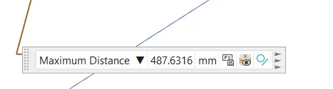
- Total length from model: 487.6316mm
*Case i) Before optimization:
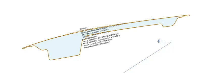
From the above figure of section Inertia Analysis, we obtained:
MOI(Max): 1.60939 x 10^7 mm^4
MOI(min) : 2.57242 x 10^5 mm^4
Y = Total length / 2
=> (487.6316)/2 = 243.8158 mm
Section Modulus(S) = [MOI(min)]/Y
=> [2.57242 x 10^5] / [243.8158] => 1.055 x 10^3 mm^3
*Case ii) with shift of inner panel by 0.5mm:
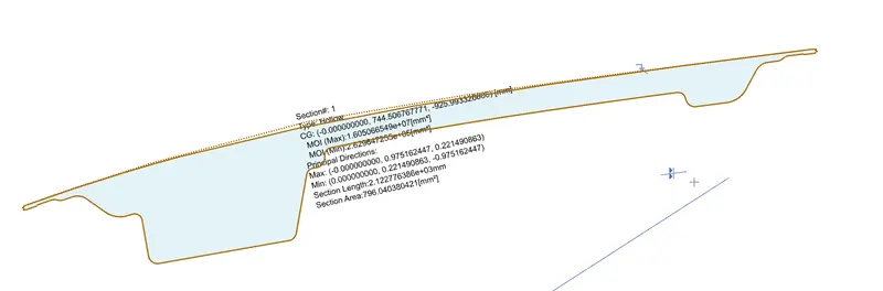
From the above figure of section Inertia Analysis, we obtained:
MOI(Max): 1.60506 x 10^7 mm^4
MOI(min) : 2.62964 x 10^5 mm^4
Y = Total length / 2
=> (487.6316)/2 = 243.8158 mm
Section Modulus(S) = [MOI(min)]/Y
=> [2.62964 x 10^5] / [243.8158] => 1.078 x 10^3 mm^3
*Case iii) After optimization:
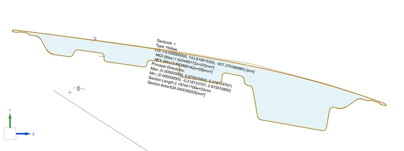
From the above figure of section Inertia Analysis, we obtained:
MOI(Max): 1.62049 x 10^7 mm^4
MOI(min) : 2.69396 x 10^5 mm^4
Y = Total length / 2
=> (487.6316)/2 = 243.8158 mm
Section Modulus(S) = [MOI(min)]/Y
=> [2.69396 x 10^5] / [243.8158] => 1.104 x 10^3 mm^3
COMPARISON:
| case i) Before Optimization | Case ii) Shift of inner panel by 0.5mm: | Case iii) After Optimization | |
|
Section Modulus (S) [x10^3 mm^3] |
1.055 | 1.078 | 1.104 |
RESULT:
We know that Higher the value of section modulus, higher will be the resistance of member to bending.
From the above comparison table we can conclude that the section after optimization has the greatest section modulus when compared to other cases.
Thus the case iii) is the most suggested model in terms of only section modulus being compared.