Week 8 - Challenge 2 - Switch Bezel Design
AIM: Create the Switch Bezel Plastic component through the given Class-A surface. To begin with, the tooling axis for the given Class-A Surface should be created meeting the requirements of the draft angle and at the end perform the Draft analysis on the model.
Take the Thickness of the component to be 2.5 mm
GIVEN:
Class A surface as shown below.

ROCEDURE:
STEP 1:
Before creating the part, it is suggested to check the draft analysis of the provided inputs (Class A Surface) and see for its feasibility of its manufacturing ability.
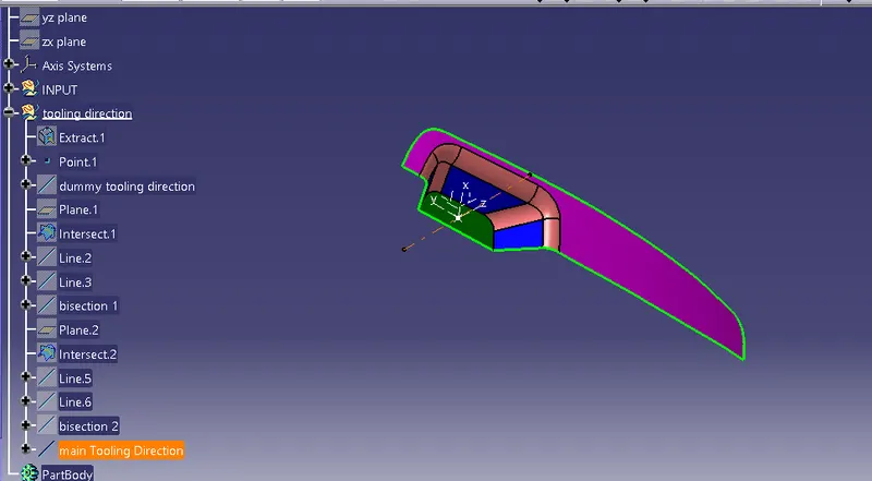
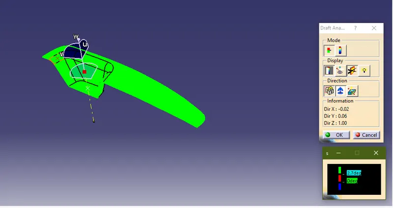
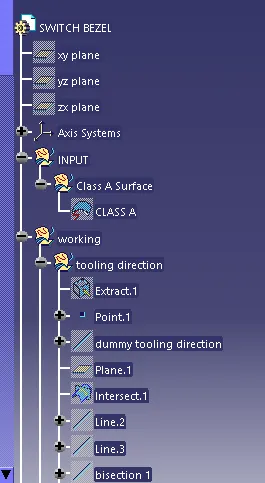
The Tooling axis is created as shown above. It is done on the point at the center of the base of handle surface, and a bisecting line between the bisecting line1 and bisecting line 2 at the same point along the Z-axis is the desired tooling direction.
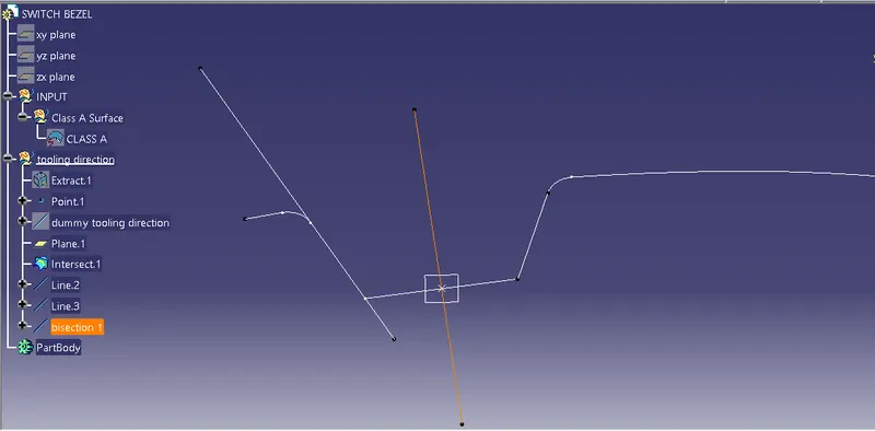
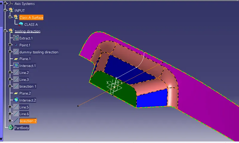
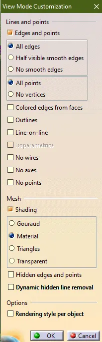
Before, we start the actual draft analysis, it is suggested to check whether the material is selected in the "view mode customization".
Below is the draft analysis result of the provided Class A Surface. The result indicates that the part can be manufactured. The minimum angle considered for the component to pass the draft analysis is 3 degrees.
STEP 2:
Now with reference to the class A surface, we create class B surface. Class B surface is also known as engineering surface.
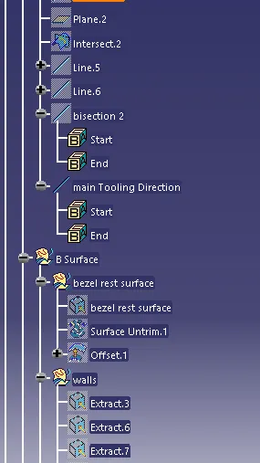
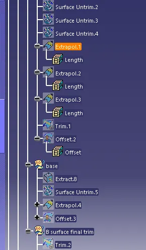
To create this we extrate the surfaces of the class A surface, untrim them, offset to the desired thickness of the part and extrapolate the surfaces.
Now, the extrapolated surfaces are trimmed to the desired shapes, with respect to the Class A surface. Apply fillets as required.
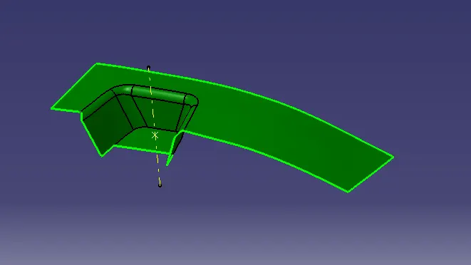
Below is the final class B surface obtained performing the above steps.
STEP 3:
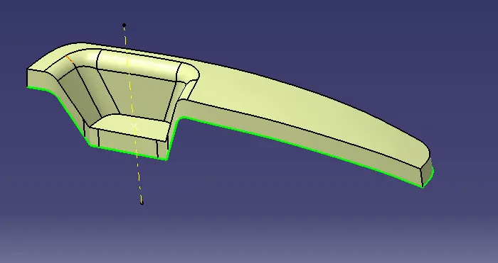
Now Class C Surface is created. This is the surface which joins the class A Surface and the Class B Surface.
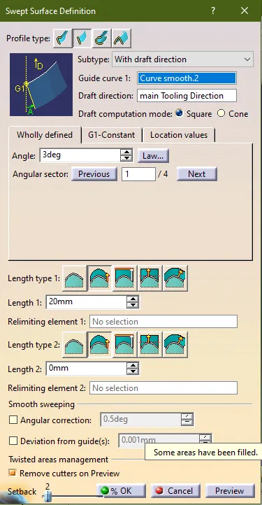
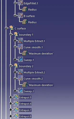
We can create it by creating the boundary of the surface which is split into 2 parts, using the multiple extract feature and make it into a continuous curves and sweep the boundary along the tooling axis with boundary surface earlier created as the guide curve as shown below.
Extrapolate the A surface by 0.05 and trim it with the swept surface. Change the angle to the value 3. And the angular sector is to be selected along the direction which the component desires.
STEP 4:
Now, the joined Class C surface is trimmed with the class B surface, to achieve the shelled part.
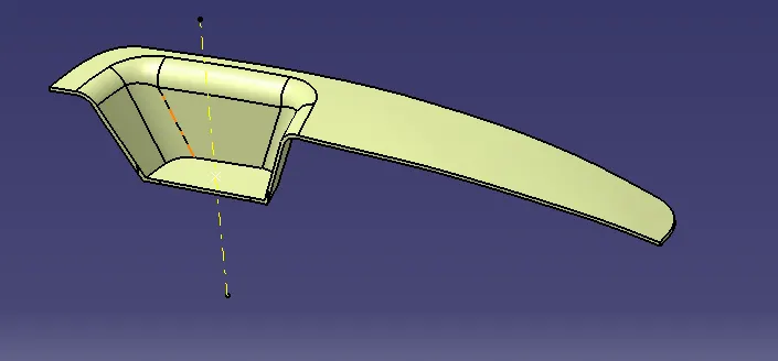
STEP 5:
Now, go the part workbench, and close the surface using the "closed surface" feature to create the part.
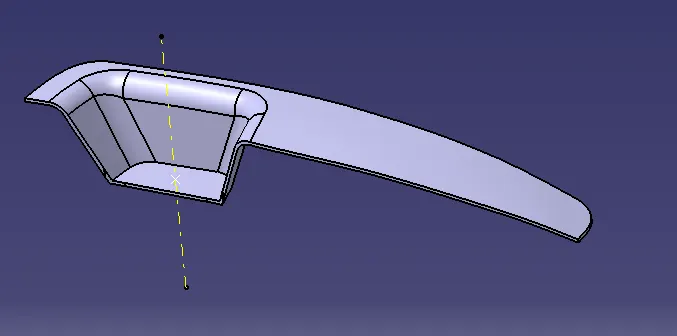
STEP 6:
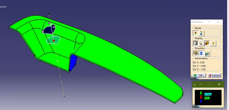
As the part is created. We need to perform the draft analysis again on the part with the tooling axis. The part draft analysis is shown below.
part draft analysis
VIEWS:
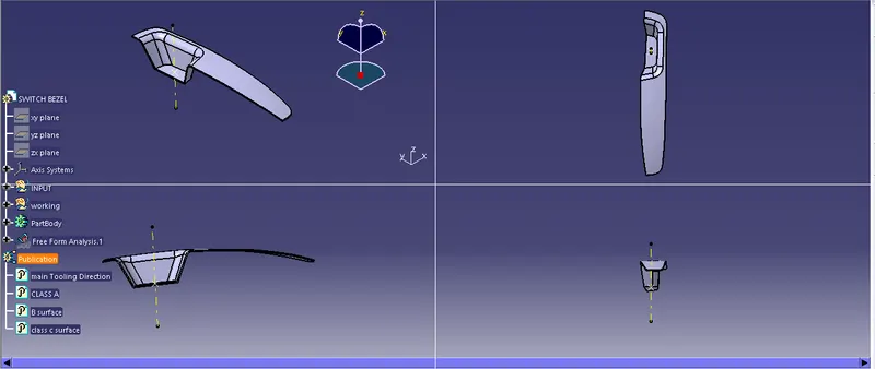
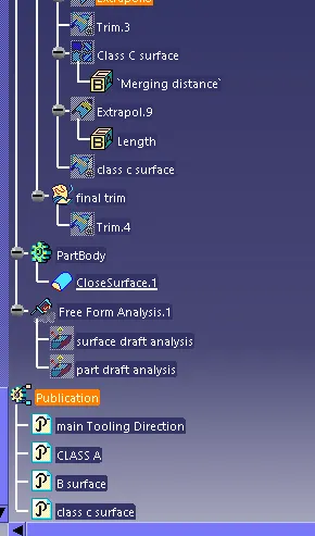
TREE:
CONCLUSION:
Thus, the Switch Bezel Plastic component is created using the given Class A Surface with the appropriate thickness.