Advanced Sheet Metal Design Using NX Cad Challenge_1_Casing Design
TITLE: Advanced Sheet Metal Design Using NX Cad Challenge 1 Casing Design
OBJECTIVE: To design a Casing with the help of NX advance sheet metal.
INTRODUCTION:
NX Sheet Metal provides a set of tools within the NX design environment that allows for simple and fast design of sheet metal parts, dependent on their material and manufacturing process. NX sheet metal design software incorporates material and process information in sheet metal-specific modelling features: bends, flanges, tabs, cutouts, beads, dimples, louvers, corner and edge treatments, patterns and other formable features.
We can also quickly convert solid models to sheet metal components, and create sheet metal parts that enclose other components.
NX Sheet Metal-specific features such as flanges, tabs, jogs, corner conditions, and drawn cutouts & many more along with productivity enhancements such as – automatic bend reliefs.
So, in this project I am going to design a Casing by using sheet metal tools and commands.
DESIGN METHODOLOGY:
| Select new file in NX cad |

| Saved with Suitable Name |
| Select the XY Plane to draw the Sketch |
| Tab is created with Reference Sketch |
| Advanced flanges on the edges of bends create in previous step |
| Bending operation done on side of the tab behind the cut out |
| on the tab created as sketch to perform normal cut out operation |
| Unbend the Sheetmetal by using unbend command |
| Added the holes where ever required by using Hole command |
| Sketch is created on the Surface of tab to perform dimple operation |
| Studio Spline option is selected to create spline curve |
| Rebend the Sheetmetal By using Rebend command |
| Beads also created with reference to holes where placed at required points Dimple operation with reference to Spline curve |
| Rotated Spline curve to 45 degree |
| final product was achieved as per the inputs |
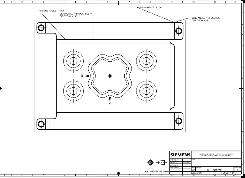
| Final Touch up was given in Drafting Sheet with suitable Scale |
DESCRIPTION:
Sketch:- It’s a basic command to draw 2d models.
Tab :- A command to add parameters of an Sketch
Bend :- It’s an operation to bend the tab at a particular position with reference
Flange :- It’s an operation to extend of a sheet metal with to one of the edge of an tab
UNBEND :- It’s an command used to flatten the created 3d model taking one face as a stationary face.
HOLE :- It’s an command used to create different type of hole like tapping and normal drilling, on the Surface of an Sheet metal.
DIMPLE :- It is a projection command of a particular shape with reference to sketch with certain depth.
BEAD :- It is also type of projection to deform the shape at a certain point with reference to sketch and also giving strength to the material.
REBEND :- This command used to re bend the already flattened sheet metal.
VIEWS:
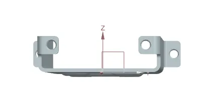
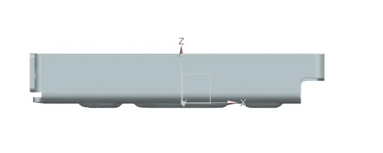
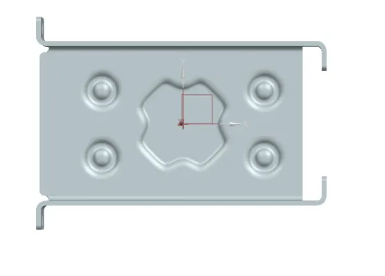
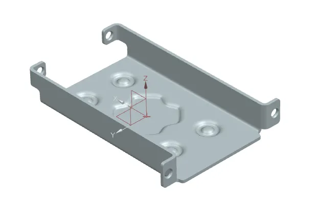
DRAFTING:
CONCLUSION:
Thus by following the above procedure, the desired sheet metal casing component is designed.