Week -2
Challenge 2a)
AIM: To make a Simulink model of doorbell using solenoid block. Considering the switch is closed for 2 seconds and then released.
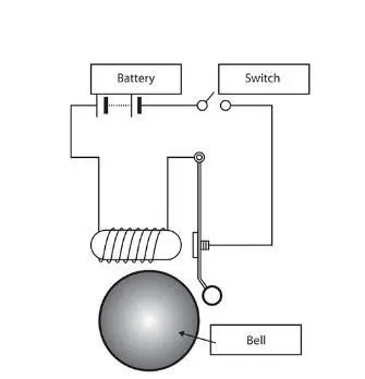
THEORY: The core conventional doorbell is a electromagnet. Electromagnets work on a very simple principle, running electric current through a solenoid (a device comprised of a coil of wire, the housing and a moveable plunger(armature) (or) it can be defined as a device which converts electric energy into mechanical work) which forms a magnetic field round the coil which draws in the plunger and hit the bell to produce a sound.
Typical working layout of a Door bell:
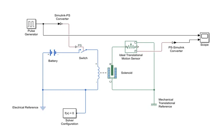
SIMULINK MODEL:
https://drive.google.com/file/d/1MntDUVAWcdGQOEr0stpBnv4gLRYOij1J/view?usp=sharing
BLOCKS USED:
Battery: It models a battery. Infinite Battery change capacity parameter is used, modelling a battery as a series internal resistance and a constant voltage source. Default settings is being used.
Switch: The block represents a switch controlled by an external physical signal. If the External physical signal PS is greater than the threshold, then the switch is closed, otherwise the switch is open. Default parameters are used.
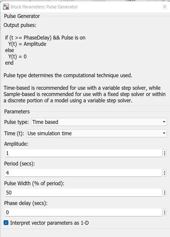
Pulse Generator: Pulse type determines the computational technique used. Time-based is recommended for use with a variable step solver, while a sample-based is recommended for use with a fixed step solver or within a discrete portion of a model using a variable step solver. The following parameters are used to obtain the result.
Simulink – PS Converter: Converts the Simulink input signal to a Physical Signal.
Electrical Reference: Electric ground. A model must contain it when the model contains a electrical system.
Solenoid: A device used to convert electric energy into mechanical work. Default parameters are used.
Ideal Translational Motion Sensor: This block measures velocity or displacement (here displacement) in a mechanical translational network. The sensor is ideal since it does not account for inertia, friction, delay, energy consumption, etc. Default settings are being used.
Mechanical Translational Reference: This block represents a mechanical translational reference point, that is, frame or a ground. Use it to connect mechanical translational ports that are rigidly affixed to the frame (ground).
PS – Simulink Converter: Converts the input Physical Signal to a Simulink Output Signal
Scope: Display signals generated during simulation.
Resistor: Provides the opposing nature of current in a circuit.
Solver Configuration: Defines solver settings to use for simulation. Default parameters are used.
OUTPUT:
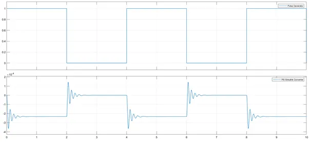
CONCLUSION: Giving time period for 2 seconds in pulse generator as input source the open and close of switch is controlled. When the switch is closed the solenoid block receives electrical power from the battery and plunger moves from ‘Port R’ to ‘Port C’ to hit the bell and produce sound. The physical movement of plunger as mentioned is observed by the translational motion sensor block and the physical output is converted into Simulink output model and displayed as plot in the scope.
***********************************
Challenge 2b)
AIM: To use a thermistor to sense the temperature of a heater and turn ON/OFF the fan as per the conditions.
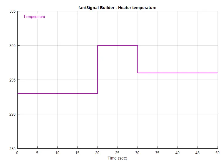
- Temperature Source: 20oC = 293K from 0 to 10 seconds, 27oC = 300K from 10 to 30 seconds, 23oC = 296K from 30 to 50 seconds.
- Fan conditions: ON if the temperature above 25oC. Else OFF
THEORY:
Thermistor is a thermally sensitive resistor which exhibits a precise and predictable change in resistance proportional to small changes in the surrounding temperature. Thus, they are perfect to detect the changes in the temperature while recording the temperature or to operate electrical appliances like fan, oven and other automobile and aerospace applications. There are different shapes and sizes of thermistors available depending upon the application it is used in. But mainly they are classified into 2 types
- Negative Temperature Coefficient Thermistor [NTC]: resistance increases with rise in temperature.
- Positive Temperature Coefficient Thermistor [PTC]: resistance decreases with rise in temperature.
In this study NTC type thermistor is used. This thermistor uses the B-parameter equation, where the resistance at temperature T is given by:
R(T) = Ro*exp(B*((1/T)-(1/To)))
Where,
Ro = nominal resistance at the reference temperature
To = reference temperature
B = characteristic temperature constant
T = sensed temperature
The default values of Ro, To and B in the thermistor parameters block of Simulink are 1000Ω, 298.15K and 3500K respectively.
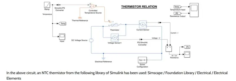
REFERENCE SIMULINK MODEL:
MODEL:
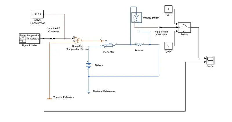
https://drive.google.com/file/d/1-TzQW-ei9cW1KXoNws1iwp13nF7XcCGI/view?usp=sharing
BLOCKS USED:
Battery: It models a battery. Infinite Battery change capacity parameter is used, modelling a battery as a series internal resistance and a constant voltage source. Default settings is being used.
Switch: This block is used from the library Simulink / Signal Routing where it has 3 inputs namely Port 1,2 and 3. Port 2 is a control input where the signal given to port 2 is satisfied with the condition and the threshold of the switch block then it passes Port 1 as output and is it is not satisfied the it will pass Port 3 as output.
The threshold of the switch is the voltage value at 298K = 0.012 (approximately) in our case.
Signal Builder: To generate the signal according to the input condition given.
Simulink – PS Converter: Converts the Simulink input signal to a Physical Signal.
Electrical Reference: Electric ground. A model must contain it when the model contains a electrical system.
Controlled Temperature Source: Provides a temperature physical output based on the condition given to post S.
Solver Configuration: Specifies the solver parameters that your model needs before you can begin simulation and this is mandatory for all simscape designs.
Thermal Reference: Provides the required initial conditions to the connected thermal block for the solver.
Thermistor: Relation between temperature and resistance. Here, NTC type is being used.
Resistor: Provides the opposing nature of current in a circuit.
Constant: Provides a constant output value.
Voltage Sensor: measure voltage across any electrical circuit.
PS – Simulink Converter: Converts the input Physical Signal to a Simulink Output Signal
Scope: Display signals generated during simulation.
RESULT / CONCLUSION:
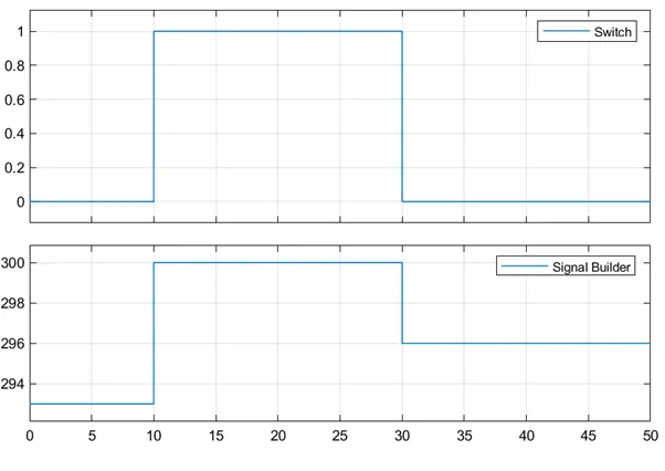
From the above plot we can observer that the switch is OFF from time 0-10 seconds and then turned ON from 10-30 seconds as the temperature value crosses the threshold temperature value followed by OFF from 30-50 seconds as the temperature falls below the threshold value.