Week 2- 2R Robotic Arm Challenge
Objective: To simulate the forward kinematics of a 2R Robotic Arm using Matlab.
Theory: A robotic arm is a type of Mechanical arm, usually programmable with similar functions resembling to a human arm. The arm is usually a combination of many links or linkages completing the desired mechanism for a machine to work. The robotic arm is used in various applications like welding, manufacturing (assembly of cars), painting, packaging industry, etc.
Approach: We are considering a 2R Robotic arm for simulating the forward kinematics, where 2 – tells us total number of links and “R” – represents that the link is a Rotational link. One end of the link say Link 1 is hinged at (X0,Y0) making an angle “angle 1/ theta1” with the horizontal. Similarly, link 2 is hinged to the other end of link one making an angle of “angle 2/ theta 2” with respect to the horizontal.
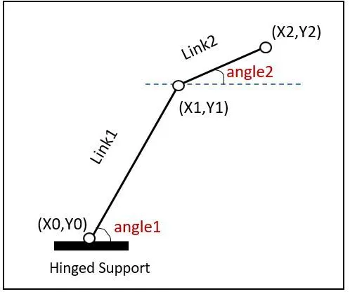
We need to animate the arm by finding out its behaviour in different conditions. For that we will follow step by step procedure starting with understanding the basic theory followed by calculations and writing the basic program and check if the desired result is achieved if not by eliminating errors of the code we run the final program with the required output.
PROCEDURE & EXPLANATION OF MATLAB CODING:
(I) Calculating the positions of LINK 1 and LINK 2
Considering the link positions as per the drawing given above. Assuming the angles made are theta1 in degrees and theta2 in degrees and the lengths of the links are l1 & l2 respectively. Using the trigonometric relations we can find the positions of (X1,Y1), (X2,Y2) that is,
X0 = 0
Y0 = 0
X1 = l1*cosd(theta1)
Y1 = l1*sind(theta1)
X2 = X1 + l2*cosd(theta2)
Y2 = Y1 + l2*sind(theta2)
(II) Writing a basic program to find the positions of the links/ arms of the manipulator
Inputs: we are assuming the lengths of links are l1 = 1 units and l2 = 0.5 units and the angles made are theta1 = 60 in degrees and theta2 = 45 in degrees. The code will be as follows:
% forward kinematics of a 2R Robotic arm manipulator with fixed angle
clear all
close all
clc

%inputs
l1 = 1; %assumed length of link 1
l2 = 0.5; %assumed length of link 2
theta1 = 60; %assumed angle made by link 1 with respect to horizontal
theta2 = 45; %assumed angle made by link 1 with respect to horizontal

% co-ordinates
x0 = 0 %link 1 x co-ordinate at rigid end
y0 = 0 %link 1 y co-ordinate at rigid end
x1 = l1*cosd(theta1); %x co-ordinate of 2nd end of link 1 and 1st end of link 2
y1 = l1*sind(theta1); %y co-ordinate of 2nd end of link 1 and 1st end of link 2

x2 = x1 + (l2*cosd(theta2)); % x co-ordinate of 2nd end of link 2
y2 = y1 + (l2*sind(theta2)); % y co-ordinate of 2nd end of link 2

% plotting
line([x0 x1], [y0 y1], 'linewidth',2,'color','b')
line([x1 x2], [y1 y2], 'linewidth',2,'color','r')
title('arm position of 2R arm manipulator')
xlabel('x axis')
ylabel('yaxis')
grid on
the graph obtained as output is as given: 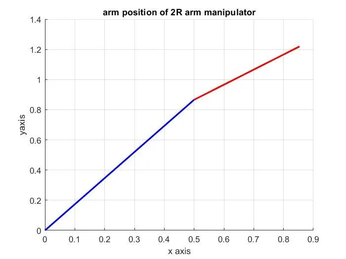
Result: Sine we have considered only fixed angles. We do not get the animated plot.
(III) Program for arm at different angles
We know that a rotational link has many different positions. Now, considering the different possible positions of an arm. We are providing inputs using the linspace command for 10 different angles as samples.
Syntax : A = linspace(0,90,10), where ‘0’ represents the starting value of the range; ‘90’ represents the ending point of the range; lastly ‘10’ represents the number of values between the range.
To change the angle for loop is introduced;
Syntax: for i = 1:10
(calculation)
End, where the for loop starts from 1 and ends doing the calculation till its value becomes 10.
Using the above cocept the code can be written as follows:
% forward kinematics of a 2R Robotic arm manipulator with multiple angles
clear all
close all
clc

%inputs
l1 = 1; %assumed length of link 1
l2 = 0.5; %assumed length of link 2
theta1 = linspace(0,90,10); %angles made by link 1 with respect to horizontal
theta2 = linspace(0,90,5); %angles made by link 1 with respect to horizontal

% implementing for loop for continous itterations
for i = 1:length(theta1) %represents the #values in angle 1 or theta1
    THETA1 = theta1(i);
    for j = 1:length(theta2) %represents the #values in angle 2 or theta2
        THETA2 = theta2(j);

x0 = 0; %link 1 x co-ordinate at rigid end
y0 = 0; %link 1 y co-ordinate at rigid end
x1 = l1*cosd(THETA1); %x co-ordinate of 2nd end of link 1 and 1st end of link 2
y1 = l1*sind(THETA1); %y co-ordinate of 2nd end of link 1 and 1st end of link 2

x2 = x1 + (l2*cosd(THETA2)); % x co-ordinate of 2nd end of link 2
y2 = y1 + (l2*sind(THETA2)); % y co-ordinate of 2nd end of link 2

% plotting
line([x0 x1], [y0 y1], 'linewidth',5,'color','b')
line([x1 x2], [y1 y2], 'linewidth',2,'color','r')
title('arm positions of 2R arm manipulator')
xlabel('x axis')
ylabel('yaxis')
grid on
    end
end
Explanation of code: The first for loop is used to get different angles of theta1 which gets saved into variable "THETA1" . Followed by for each value of 'THETA1' the 2nd for loop gets iterated untill the condition is satisfied for the 2nd loop, where the each possible angle of theta2 is stored in the variable "THETA2". Now the 2nd iteration of the 1st for loop gets started. This process goes on until the condition mentioned in the for loops are satisfied.
output:
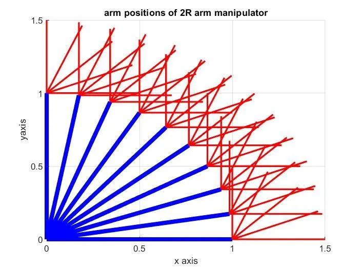
Result: As we can notice that all the possible outcomes are shown in one graph, which looks complicated in understanding. We can upgrade the code by implementing a concept of creating a video for which we are defining a variable named "ct=1" which will count the frames.
(IV) Program for arm animation (error elimination)
To animate the plots we are considering a variable ct with value 1 before the for loop code. This variable is incremented by 1 in the for loop. Which gets iterated with respect to the for loop conditions (collecting every frame).
Pause command is used to animate the arm by pausing the arms at each possible condition. Which will help us in creating the movie/ animation. Which is created in “avi” format, using the movie function and videowriter command.
NOTE: Since the Matlab codes are "case sensitive" utmost care is taken in writing the command names and functions.
Considering the above note, the program is written as follows:
% forward kinematics of a 2R Robotic arm manipulator with multiple angles
% and animation
clear all
close all
clc

%inputs
l1 = 1; %assumed length of link 1
l2 = 0.5; %assumed length of link 2
theta1 = linspace(0,90,10); %angles made by link 1 with respect to horizontal
theta2 = linspace(0,90,5); %angles made by link 1 with respect to horizontal
ct = 1; % declaring variable to count frames

% implementing for loop for continous itterations
for i = 1:length(theta1) %represents the #values in angle 1 or theta1
    THETA1 = theta1(i);
    for j = 1:length(theta2) %represents the #values in angle 2 or theta2
        THETA2 = theta2(j);

x0 = 0; %link 1 x co-ordinate at rigid end
y0 = 0; %link 1 y co-ordinate at rigid end
x1 = l1*cosd(THETA1); %x co-ordinate of 2nd end of link 1 and 1st end of link 2
y1 = l1*sind(THETA1); %y co-ordinate of 2nd end of link 1 and 1st end of link 2

x2 = x1 + (l2*cosd(THETA2)); % x co-ordinate of 2nd end of link 2
y2 = y1 + (l2*sind(THETA2)); % y co-ordinate of 2nd end of link 2

% plotting
plot([x0 x1],[y0 y1],[x1 x2],[y1 y2],'LineWidth',3)
axis([-0.1 1.5 0 1.5 ])
xlabel('x axis')
ylabel('y axis')
pause(0.5)
M(ct)=getframe(gcf);
ct = ct+1;
    end
end

movie(M) %calling movie function
videofile = VideoWriter('forward_kinematics.avi','Uncompressed AVI'); %creating a %variable called 'videofile' and writing video using "VideoWriter" command and %generating an uncompressed file named "forward_kinematics" in "avi" format.
open(videofile)
writeVideo(videofile,M)
close(videofile)
Explanation of code: The graph is plotted using the 'getframe(gcf)' command inside the 2nd for loop. So that it can get the current frame and store it as an image into the array 'M'.
The "VideoWriter" command and mentioned earlier creates an empty video file named 'forward_kinematics' inreturn stored in the variable videofile.
The 'writeVideo' command inserts all the stored frames in the array 'M' into the videofile, generating the animation given in the result below.
Result: The video file is made and published in drive. The animated plot of the 2R arm of a Robotic manipulator is as shown: (refer link)
https://drive.google.com/file/d/1t9BvP8FOMOw6fCBh4i40le2dQn-iS8lF/view?usp=sharing