Week 8 - Challenge 3 - Coin Holder Design
AIM: Create the Coin Holder Plastic component through the given Class-A surface. To begin with, the tooling axis for the given Class-A Surface should be created meeting the requirements of the draft angle and at the end perform the Draft analysis on the model.
Take the Thickness of the component to be 2.5 mm
GIVEN:
Class A Surface
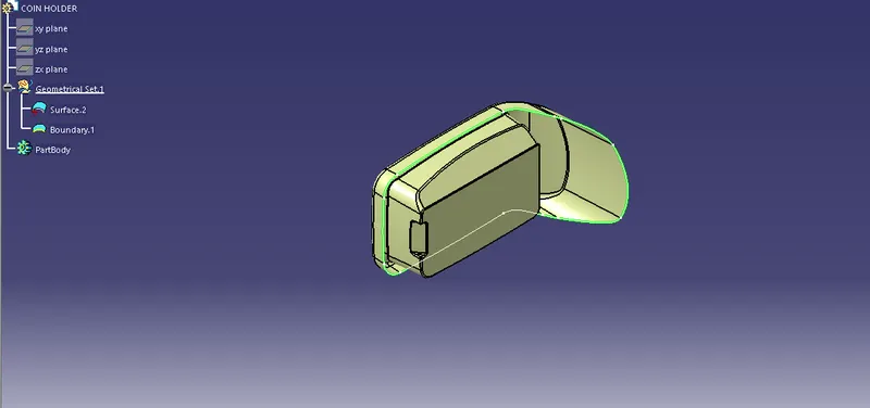
STEP 1: The given class A surface is checked for number of elements it has. Usually, it is preferred to have only single element.
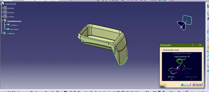
STEP 2: The tooling axis is created, as the base of the given surface is flat with side wall at 90 degrees with the base. We can assume the tooling direction is normal to the base of the surface.
STEP 3: With reference to the tooling axis, the draft analysis on the class A surface is performed. The result is shown as below.
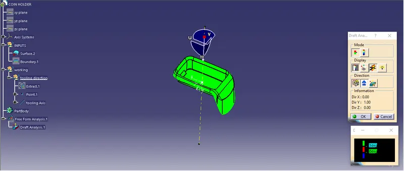
STEP 4: Now the B Surface is created which is at an offset of 2.5mm to the A surface.
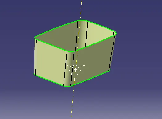
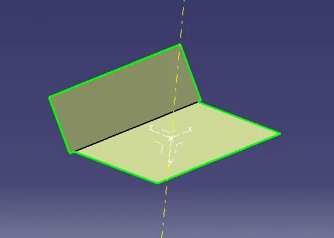
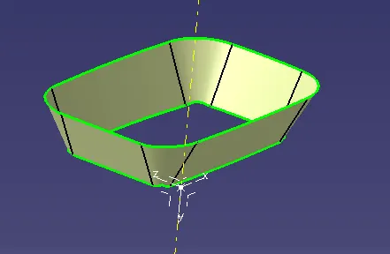
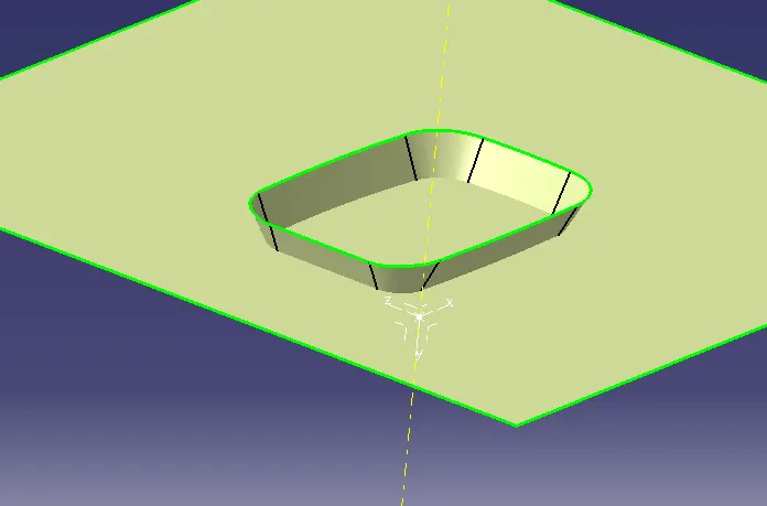
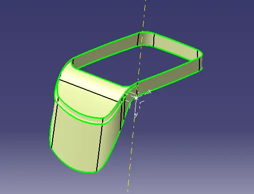
First we start with extracting the side walls, untrim them, offset them in the desired direction and extrapolate. Similarly we follow the same method for the base, top wall, internal tapered surface, and outer flange.
side walls:
Base:
Top wall:
top wall flat surface:
outer flange:
STEP 5: Now trim all the above surfaces to form the class B surface. And give appropriate fillets at corners.

STEP 6: Now we need to make a class C surface. It is done as shown below.
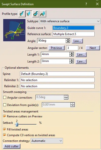
Trim the C surface with the class A surface.
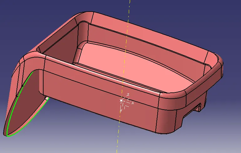
STEP 7: Trim the class C with the class B Surface.
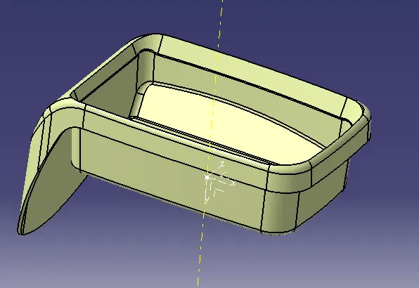
STEP 8: Close the surface to convert it into the part body.
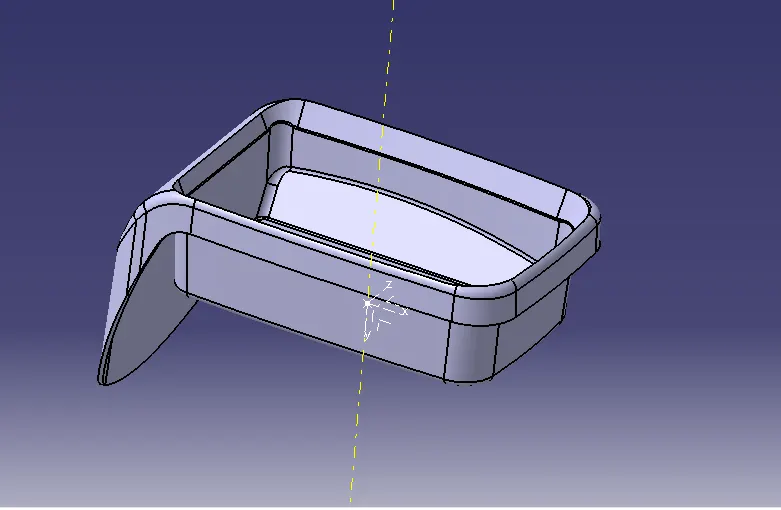
STEP 9: Perform Draft Analysis on the part.
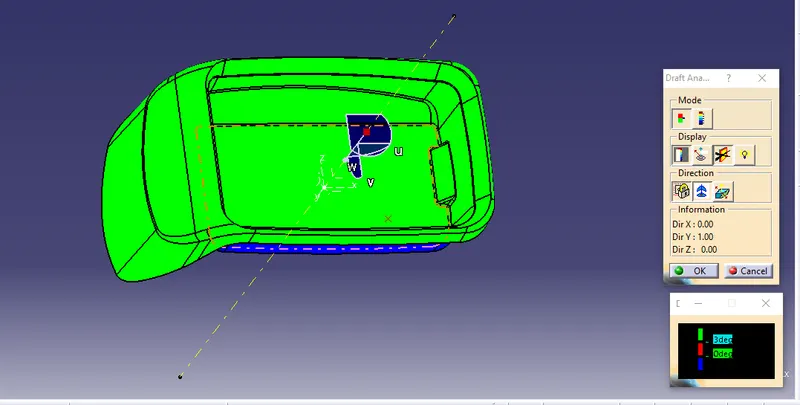
From, the part draft analysis we can see that the part can be manufactured.
VIEWS:
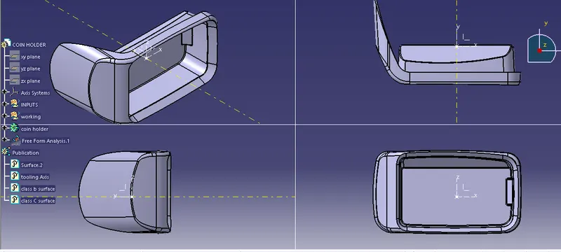
CONCLUSION: Thus, a Coin Holder is created with said thickness using the above procedure.