Project
AIM: To carry out a system - level simulation of an All - Terrain Vehicle (ATV).
THEORY:
An All- Terrain Vehicle(ATV) also known as Light Utility Vehicle(LUV) or a Quad Bike(sometimes only Quad) as defined by the American National Standards Institute (ANSI); is a vehicle that travels on low pressure tires, with a seat that is straddled by the operator, along with handlebars for steering control.
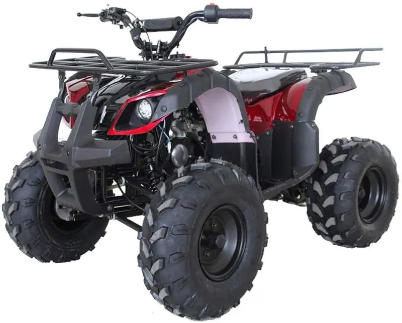
ATVs are intended for use by a single operator, although some models are delveloped with a capacity of 1 passenger as extra.
Parts of an ATV:
- Chassis / Vehicle Body
- Suspensions
- Tires
- Engine
- Continuously Variable Transmission (CVT)
BLOCKS USED:
- Signal Builder: This block allows you to create and generate interchangeable groups of signals whose waveforms are piecewise linear.
- GoTo: This block passes its input to its corresponding From block. From and GoTo blocks allows you to pass a signal from one block to another without actually connecting them.
- Simulink - PS Converter: Converts input signal into physical signal.
- PS - Simulink Converter: Converts physical signal into Simulink output signal.
- Generic Engine: Represents a general internal combustion engine. It is a suitable generic engine for spark ignition and diesel. By default, this block uses a programmed relationship between torque and speed that is modulated by the throttle signal.
- Solver Configuration: Specifies the solver parameters that your model needs before you can begin simulation.
- Mechanical Rotational Reference: It represents a reference point, or frame, for all mechanical rotational ports. All rotational ports that are rigidly clamped to the frame (ground) must be connected to a Mechanical Rotational Reference block.
- Engine Sensor: This sensor is connected with a Generic Engine. It consists of physical modeling Connection Port block for subsystems. Ideal Mechanical Rotational Sensor block measures angular velocity or angle in a mechanical rotational network. The sensor is ideal since it does not account for inertia, friction, delays, energy consumption and so on. This sensor is further connected with a CVT subsystem.
- Simple Gear: Represents a fixed ratio gear or gearbox. No inertia or compliance is modelled in this block. It includes gear meshing, backlash, and viscous bearing losses.
- Chart: Implement control logic with finite state machine
- From: This block passes its output to its corresponding Goto block. From and GoTo blocks allows you to pass a signal from one block to another without actually connecting them.
- Scope: Displays signals generated during simulation.
- CVT Subsystem:
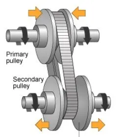 The CVT mainly consists of (i) primary pulley, (ii) Variator, (iii) Secondary Pulley and (iv) Belt. working under the conditions (a) If the primary pulley moves inward while the secondary pulley moves outward then it will lead to Overdrive(Rp > Rs). (b) If the primary pulley moves outward and the secondary pulley moves inward then it will lead to Speed reduction(Rp<Rs). This CVT subsystem consists of various blocks such as input & Output shaft Inertia, Variable Gear Transimission Sensors and PS Terminator along with Mechanical Rotational Reference.
 - Vechicle Body: Represents a 2-axle vehicle body in logitudinal motion. The block accounts for body mass, aerodynamic drag, road incline, and weight distribution between axles due to acceleration and road profile. The vehicle can have the same or a different numbers of wheels on each axle. Optionally include pitch and suspension dynamics or additional variable mass and inertia. The vehicle does not move vertically relative to the ground. It consists of 4 wheels, The rear wheels are connected with a double shoe brake which represents a brake arranged as 2 pivoted rigid shoes symmetrical installed inside or outside a drum and operated by one actuator. The actuator force causes the shoes to exert friction torque on a shaft connected to the drum.
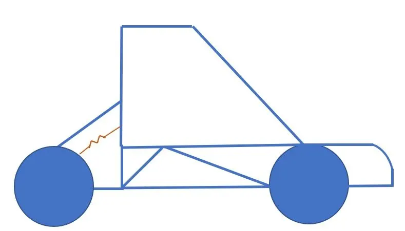
STUDY 1 : ATV with CVT
Model:
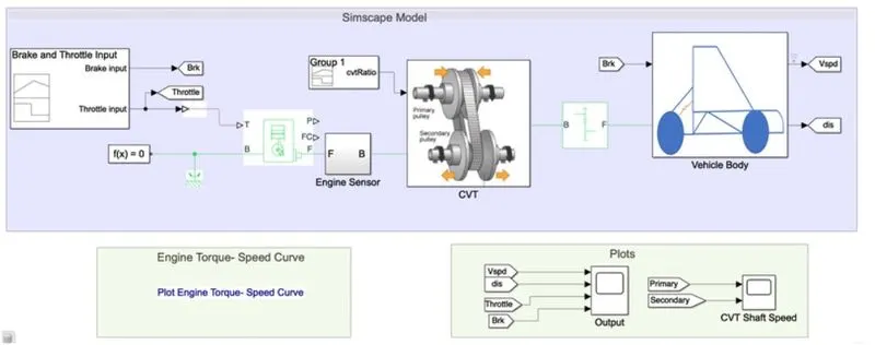
Explanation:
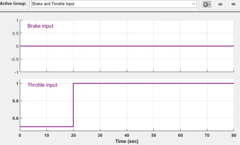
* The Brake input is kept constant( it is zero throughout the given 80 seconds time period).
* Throttle input is assumed to be 0.5 for 20 seconds, later increased to 1 and maintained till the end of the time.
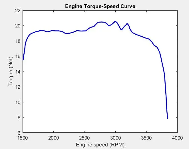
Engine Torque - Speed Curve
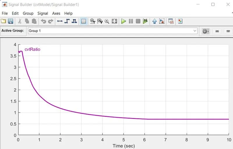
Vehicle Speed depends on CVT Ratio. The data is extracted using the GRABIT command which is available in the workspace.
CVT Ratio:
RESULTS:
Vehicle Speed
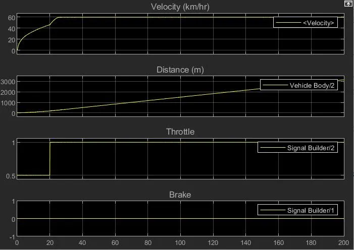
While providing Throttle input, we have considered 0.5 units for smooth flow of velocity.
CVT Shaft Speed:
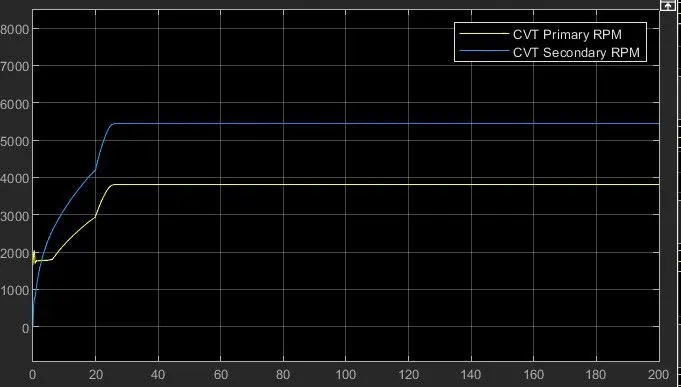
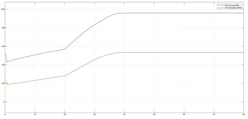
The CVT shows variations with respect to primary and secondary RMP based in their Gear Ratio.
STUDY 2: ATV with CVT and Dashboard
Model:
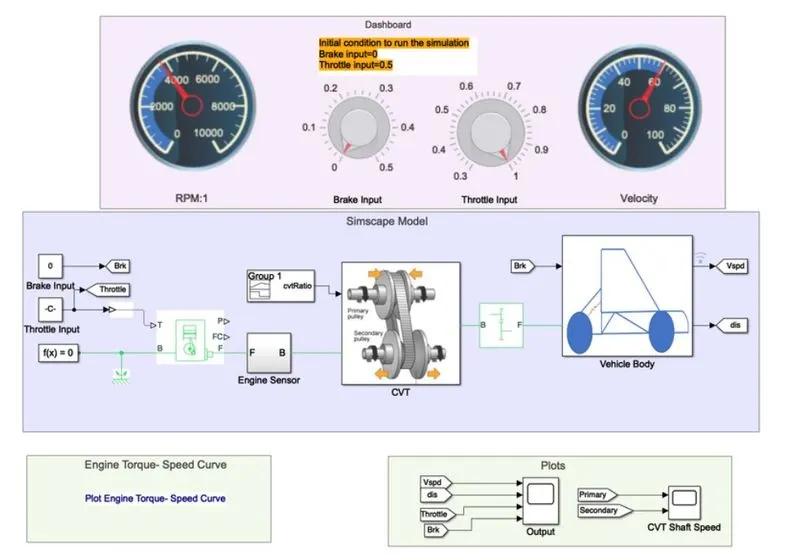
Explanation:
* This model is similar to the above case but with dasboard block with the ability for the user to change input values during the run of simulation as additional feature.
* Brake input is kept constant similar to above.
* The change in throttle inputs is provided by the user which results in the change in the vehicle speed.
RESULTS:
ENGINE Speed:
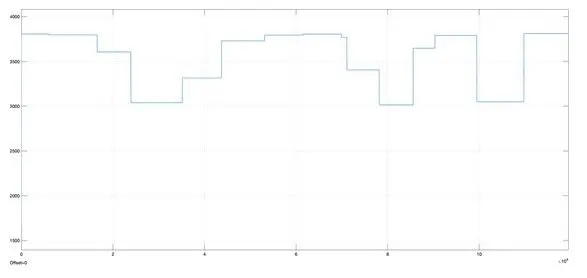
CVT
vehicle speed:
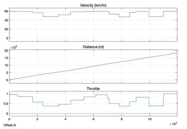
Knob in dashboard is used to alter the input of Throttle.
CVT Shaft Speed:
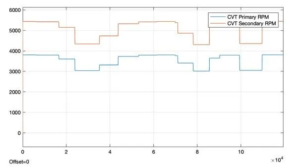
The above graph shows the variations with respect to primary and secondary RPM based on their Gear Ratio.
STUDY 3: ATV with CVT using lookup tables without dashboard
model:
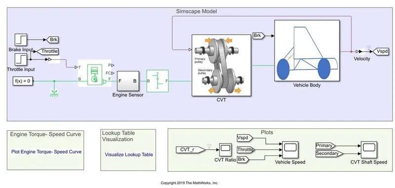
LOOKUP TABLE: It is an array of data that maps input values to output values, thereby approximating a mathematical function. Given a set of input values, a lookup operation retrieves the corresponding output values from the table. In place of CVT ratio input, a lookup table is assigned in the models below. It needs to be loaded in the workspace having the file name as "Lookuptable_data.mat"
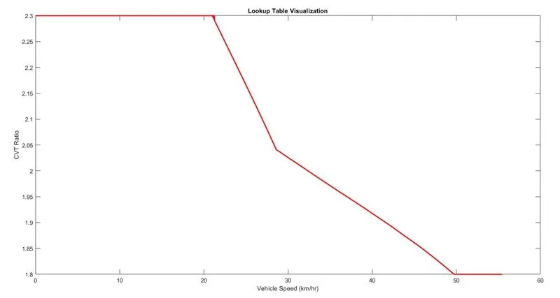
CVT Ratio vs Vehicle Speed:
0 to 20 kmph, the CVT Ratio is constant at 2.3
20 to 30 kmph, the CVT Ratio drops to 2.03
30 to 50 kmph, the CVT Ratio drops further down to 1.8
50 kmph onwards, the CVT Ratio remains constant at 1.8
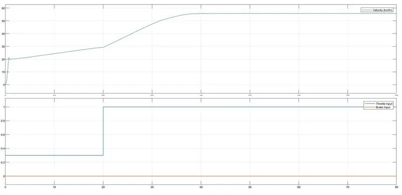
The following are given as inputs in the step block:
for brake Input: Step time=35, Initial value=0, Final value=0, and Smple Time=0
for Throttle Input: Step time=20, Initial value=0.3, Final value=1, and Smple Time=0
RESULTS:
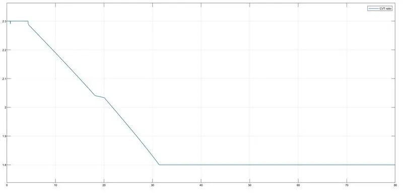
CVT RATIO:
Vehicle speed:
CVT Shaft speed:
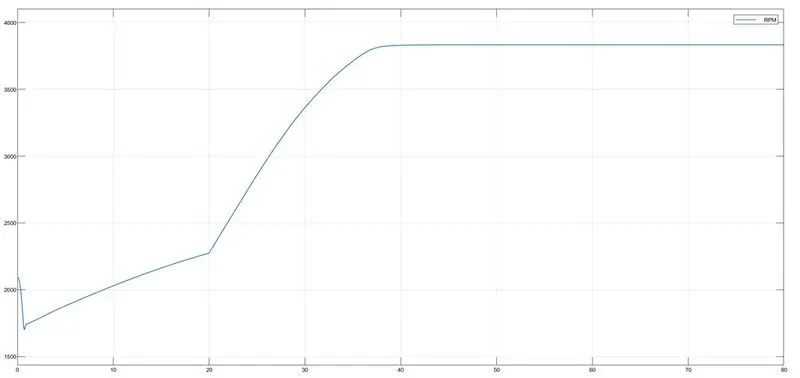
Engine Speed:
STUDY 4: ATV with CVT, Dashboard and Lookup Tables
model:
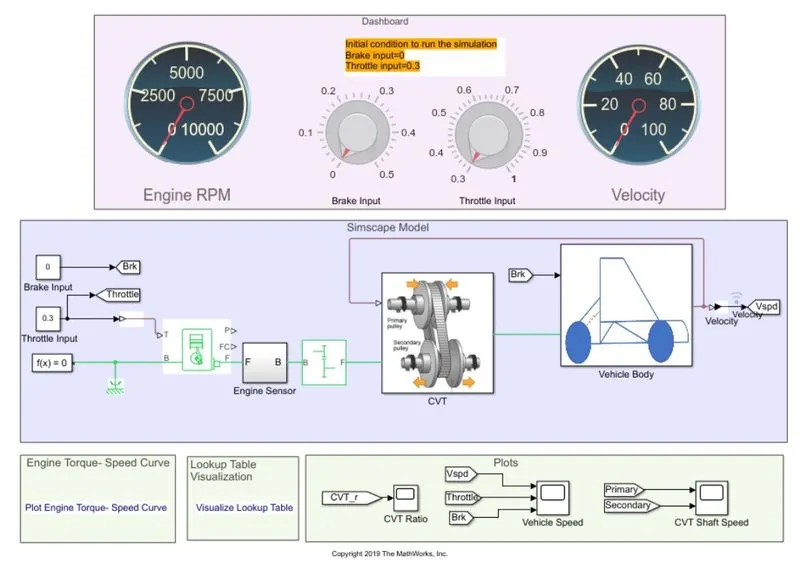
RESULT:
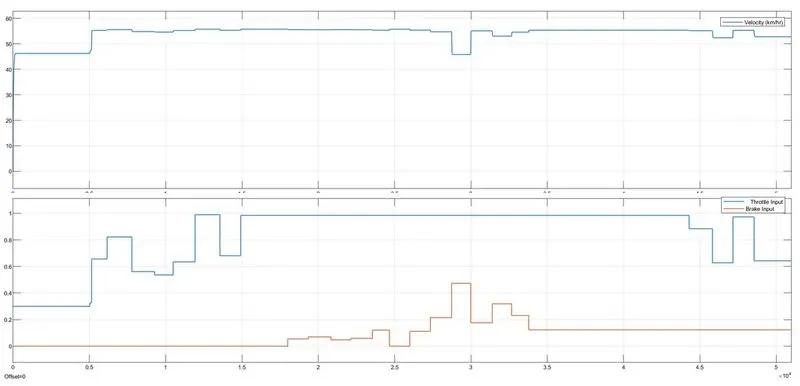
for the inputs the following outputs are achieved
Vehicle Speed:
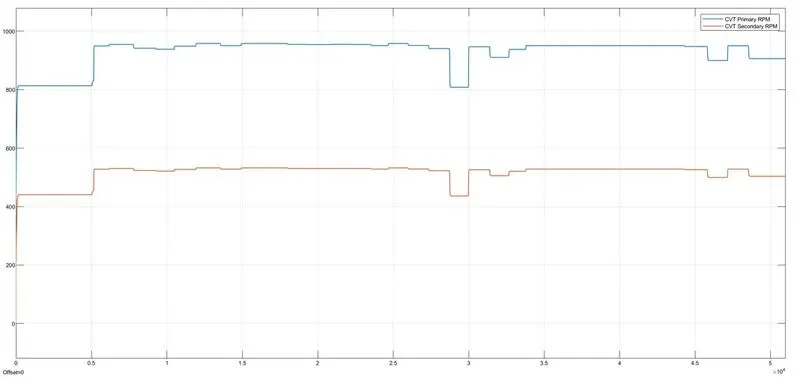
CVT Shaft Speed:
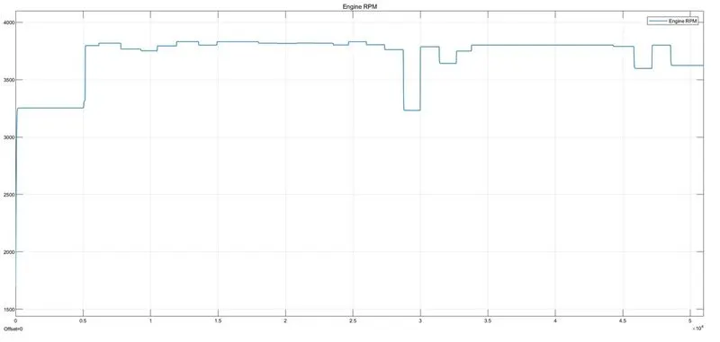
Engine Speed:
CONCLUSIONS:
The given BAJA ATV Model was simulated successfully and from the above results, we can conclude that:
* Velocity, CVT Shaft Speed and Engine Speed are directly proportional to the Throttle input and inversely to the Brake input.
* CVT primary speed is > CVT secondary speed as they are directly proportional to their shaft diameter.
* The speed might get null at a particular braking resistance.
Thus helping us in determining the vehicles performance.
REFERENCES: