Creating Levels, Grids, Layout and model elements for a residential unit using REVIT
1 ans:
- BIM means Building Information Modeling
- BIM is an acronym for Buiding Information Modeling or Buiding Information
- It is a highly collaborative process that allows architects, engineers, real estate developers, contractors, manufacturers, and other construction professionals to plan, design, and construct a structure or building within one 3D
- It can also span into the operation and management of buildings using data that building or structure owners have access to (hence the Building Information Management).
- This data allows governments, municipalities, and property managers to make informed decisions based on information derived from the model even after the building is constructed
Features of BIM:-
- BIM is a physical representation of the physical and functional characteristics of the building process, that provides every minute detail of the project
- Every stakeholder makes their discipline-specific input to make it a piece of comprehensively shared information resource about the structure.
- One can easily access the right information at the right time that provides a reliable basis for decision-making during a structure's entire lifecycle.
- BIM models not only present a 3D geometric view of the structure but also provide a more comprehensive overview of the entire building process.
- It covers every component of this process from the geometrical aspect of the design to spatial relationships, from light analysis to provision of various services, from topographical information to quantities or properties of building components, and so on.
- BIM design tools allow you to obtain various views from a building model and produce high-quality, accurate drawings. These views are based on a single definition of each object and thus gives a more realistic and accurate idea of the final structure.
Benefits of using BlMover 20 CAD tools:-
- Three-dimensional Building Information Modeling (BIM) provides many advantages over 2D CAD due to the vast capabilities of parametric modeling.
- All components modeled in 3D BIM software contain real wor d information about that
- For instance, if you were to place a wall within a BIM model, that wall would automatically include information about it such as its length, width, volume, weight, with little to no additional input from the user. Because of this, once the 3D models complete the information can quickly and easily be translated into schedules, drawings, and much more.
2 ans:
Category: A Category controls the organization, visibility, graphical representations, and scheduling options of Families within the Project.
Family: A Family is a grouping of 2D and/or 3D pieces of information that serve to represent a discrete building or documentation element in the Project. It defines parametric, graphical, and documentation requirements.
There are three kinds of Revit Families
- System: These are the families that are pre-defined families specific to a Revit Their parametric, graphical, and documentation requirements already exist. They can not be created in, deleted from, loaded into, or saved out of the current project.
- Loadable: These are the families that are user-defined families built in an editing mode cal ed the Family Editor using family templates. Their parametric, graphical, and documentation requirements can be defined from scratch. They can be created and loaded into a project as well as, deleted or saved from a project
- In-Place: These are the families that are user-defined families created to represent a one-of-a-kind element unique to the Like System families they cannot be loaded into or saved out of a project but, they can be created within the context of the project using familiar Family Editor tools.
- Element: A Element is a specific representation in a Family defined by distinct parametric, graphical, and documentation characteristics which makes it unique from other Types in the Family.
- Instance: An Instance is an individual representation of a Type in the Project defined by unique parametric, graphical, and documentation characteristics which makes it unique from other Instances in the Project
Aim: To create a family in Revit
Procedure:
- Open Revit software
- Now click on any template
- Now you will get a workspace
- Now go to workspace and click on Load families as shown

- Now a popup box will open select libraries and click open
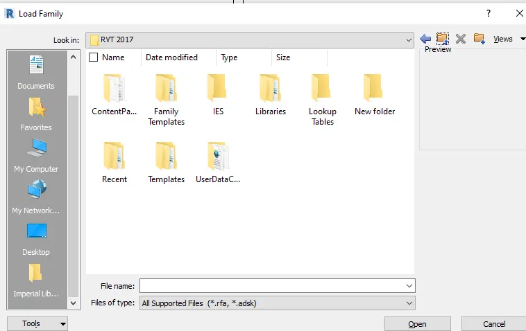
- Now click on India and Click open
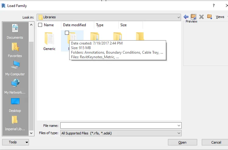
- Now a dialogue box appears now click on doors
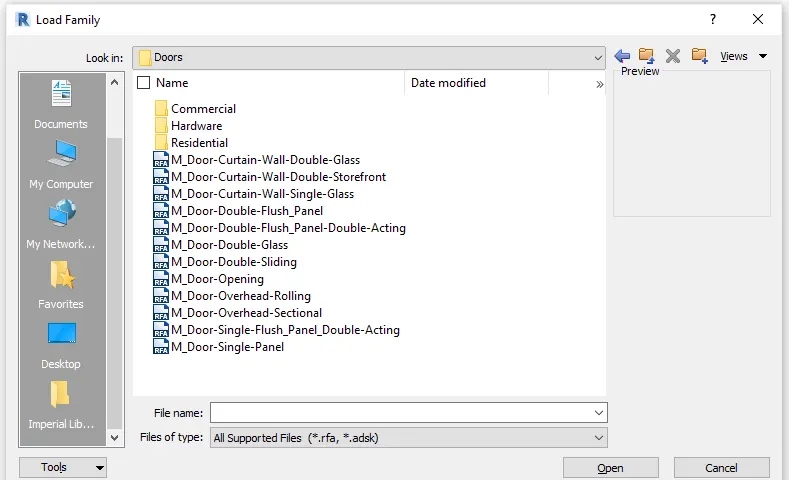
- Now click on M-door single panel
- Now a dialogue box opens with a different type of door sizes
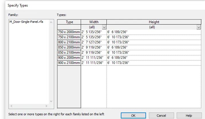
- Now select750x2000mm element and click ok
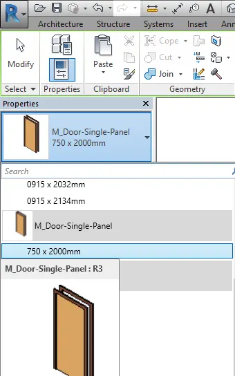
- Now the door gets loaded in the door properties in the architecture tab
- Now go to the architecture tab and select the door loaded as shown
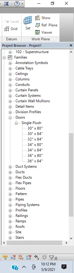
- Families can also be added from the project browser also
3 ans:
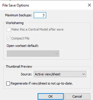
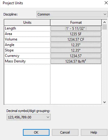
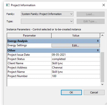
Aim: To Setting up a Project – Open a project file with an architectural template. Save the file with an appropriate name. Set up the project units to Imperial / Metric based on your convenience of modeling. Complete the project information under the Manage tab. Set up the maximum backups for project file to 3
Procedure:
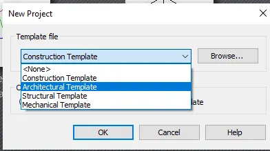
- Open Revit
- click on the new and select architectural template as shown
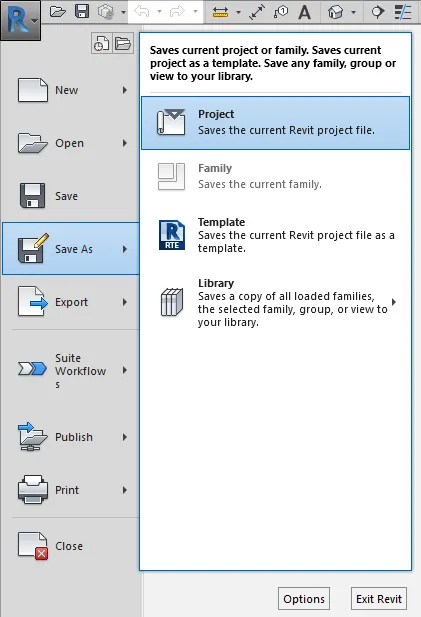
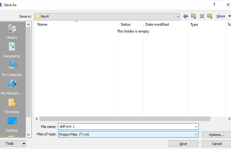
- Now click on R (file) and select save as
- Now select project
- Now a dialogue box will appear
- now give as skill Lync 1 and click options as shown
Now a small dialogue box will appear now set the no. of backups as 3 as shown
- Now click the manage tab click on project units
- Now a small dialogue box will appear
- Now change the units accordingly
- Now click the manage tab and select the project information
- Now a dialogue box of project information opens
- Now edit the information as per our convenience
4 ans:
Aim:To Create the following Levels: ( Convert to metric equivalents if the metric is your units)
Ground Floor @ 0’
First Floor @ 10’
Second Floor @ 20’
Roof @ 30’
Procedure:
- Open Revit software
- open any template
- Now a workspace will open
- Now in the project browser select any elevations
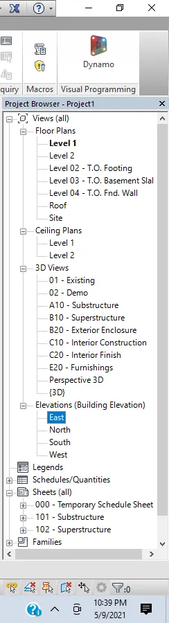
- Now we get east elevation of workspace with some levels as shown
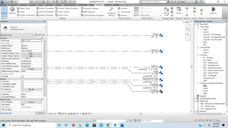
- Now change the level 1 to ground and level 2 to 1st and roof to 2nd and add one more level
- To create one more level we have to click on the level and name the level as roof
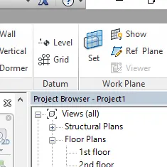
- Now click on the floor plan and level 1
- Now select the grid
Now draw lines vertically with an offset of 20' and give them numbering as shown
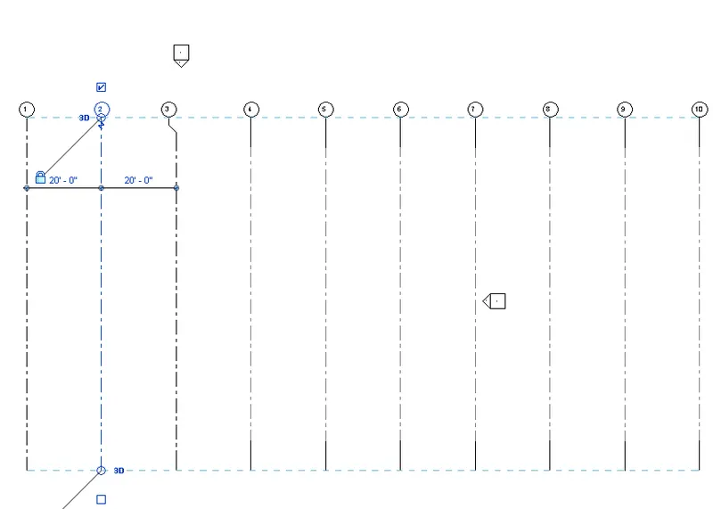
Now draw lines horizontally with an offset of 10' and give them Alphabets as shown
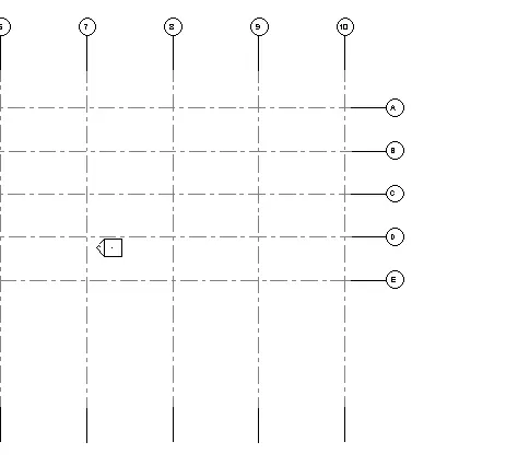
Result:
5 ans:
Aim: To create a 3D model unit
Procedure:
- Open Revit
- click on the new and select architectural template as shown
- Now click on R (file) and select save as
- Now select project
- Now save the project and open the workspace
- Now draw a plan using wall as shown
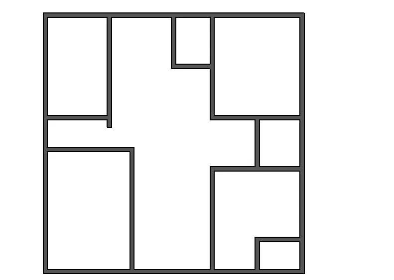
- Now change it to 3d view as shown
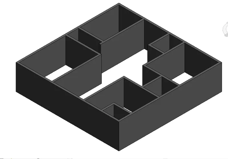
Result:
6 ans:
Aim: To give Dimensions and components to the drawn file
Procedure:
- open the plan that drawn in last question
- Now keep it 2d view and give dimensions
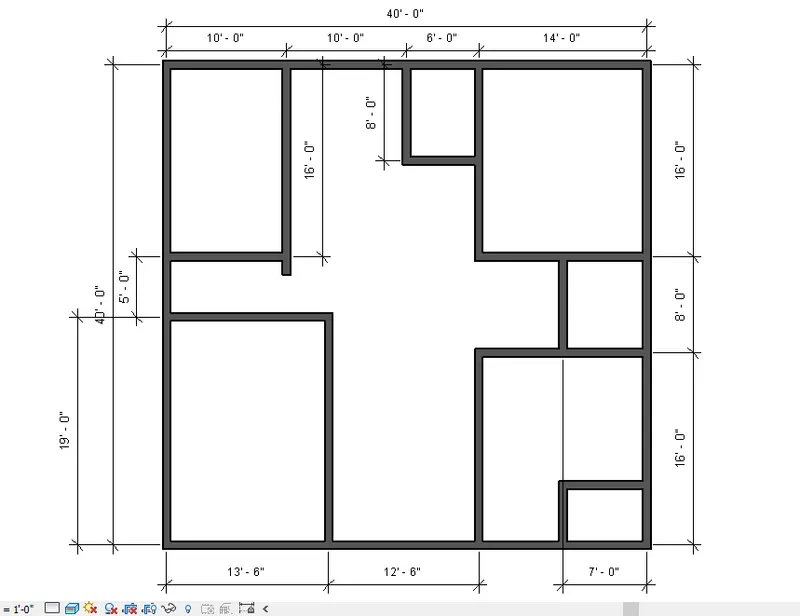
- Now open annotate and click on the text and give the names of the rooms
- Now add components as shown
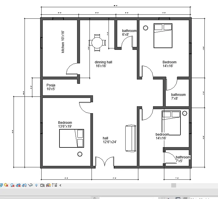
- Now keep it in 3d view as shown
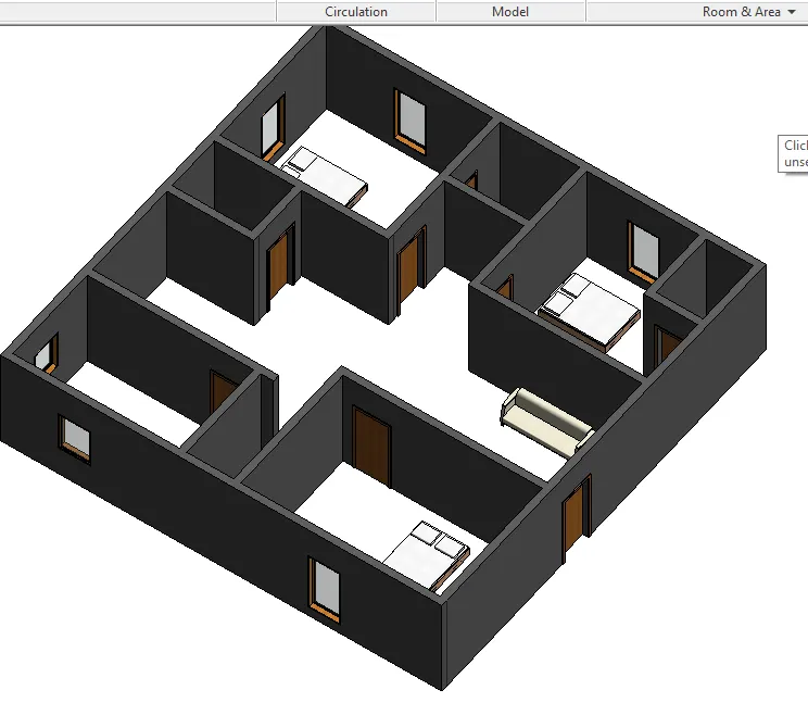
7 ans:
Aim:To insert elements such as Door, Windows, Tables, Chair, Couch, Bed, Lamps from the library
Procedure:
- open the plan that drawn in last question
- Now keep it 2d view
- Now to add doors windows tables chairs from the library we have to click on insert and click on load family
- Now a new dialogue box will open click on India and select the required components from folders
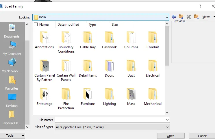
- After loading the components in Revit
- Now click on components to place the components in the plan

- Now place it as shown in figure
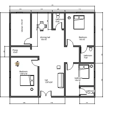
- Now set in 3D view
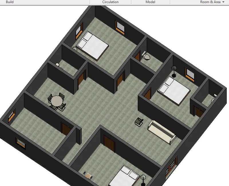
Result:
This result is the combination of 5,6,7