Modelling of 25 storey building with the specified properties using ETABS
Aim: To Model and analyze a 25 storey building with the specified properties using ETABS
Procedure:
- Open ETABS 18 application
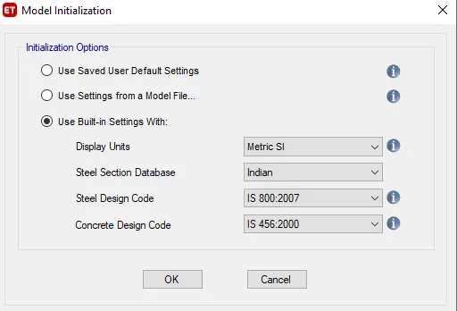
- Now model initialization tab opens
- Now select Use built-in settings with and select Indian in steel section database and select codes accordingly and click ok
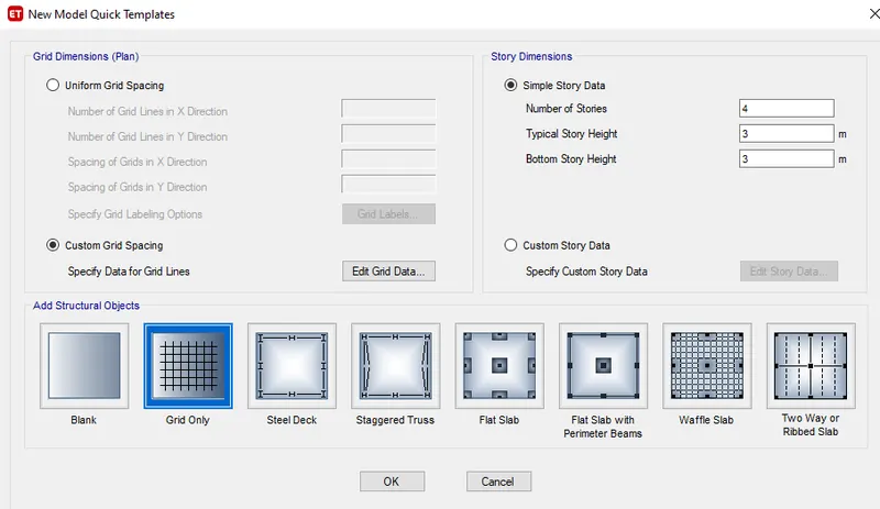
- Now new tab opens
- Now select the custom grid spacing and select grid only
- Now click on Edit grid data
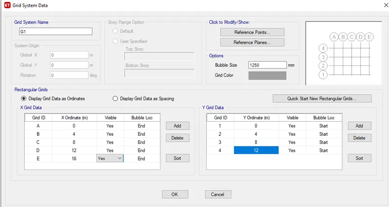
- Now we get a new tab as shown
- Now arrange x grid data and y grid data as required
- Now click ok
- Now select custom story data and select edit story data
- Now we get a new tab
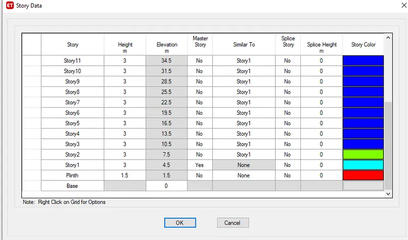
- Now right-click on any story and we get a new tab
- Now add the number of added stories accordingly as required and click ok
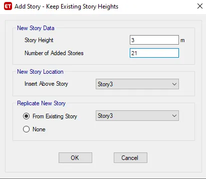
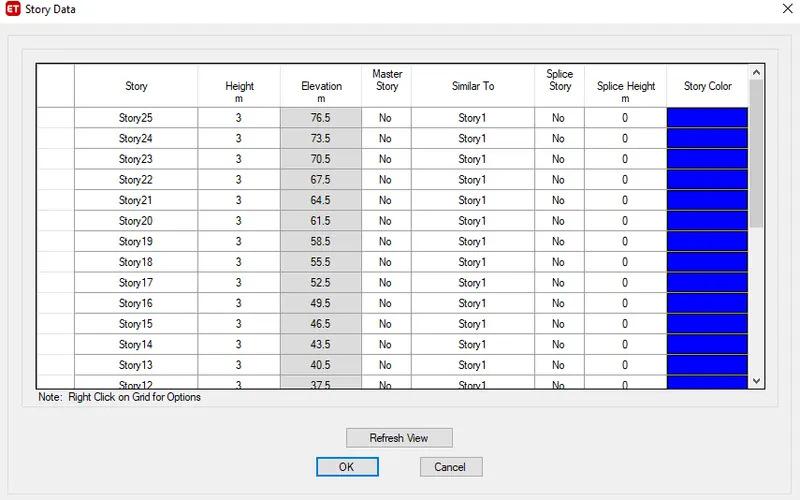
- Now we the story data tab as shown below
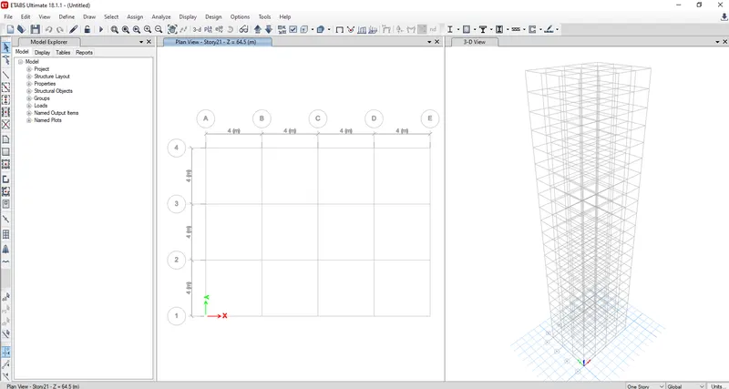
- Now click ok we the model as shown
- Now go to define option and select material properties
- After selecting material properties we get a define material tab
- Now in define material tab select add new material properties as shown
- Now select material type as concrete and grade as M30 and click ok
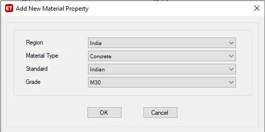
- Now in define material tab select M30 and click on modify/show material
- Now we get the material property tab and click ok
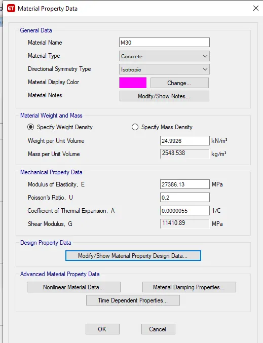
- Now go to define option and select material properties
- After selecting material properties we get a define material tab
- Now in define material tab select add new material properties as shown
- Now select material type asrebar and grade as Hysd 500 and click ok
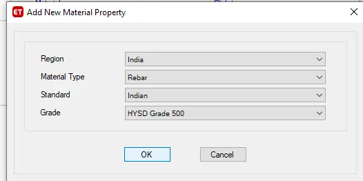
- Now in define material tab select Hysd500 and click on modify/show material
- Now we get the material property tab and click ok
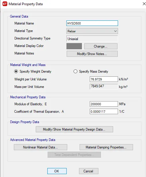
- Now go to define option and select material properties
- After selecting material properties we get a define material tab
- Now in define material tab select add new material properties as shown
- Now select material type asrebar and grade as Hysd 415 and click ok
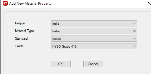
- Now go to define and section properties and select frame sections as shown
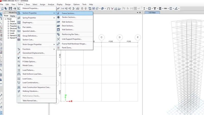
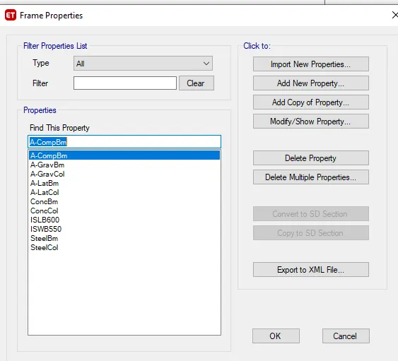
- Now we get the frame properties tab select add new property
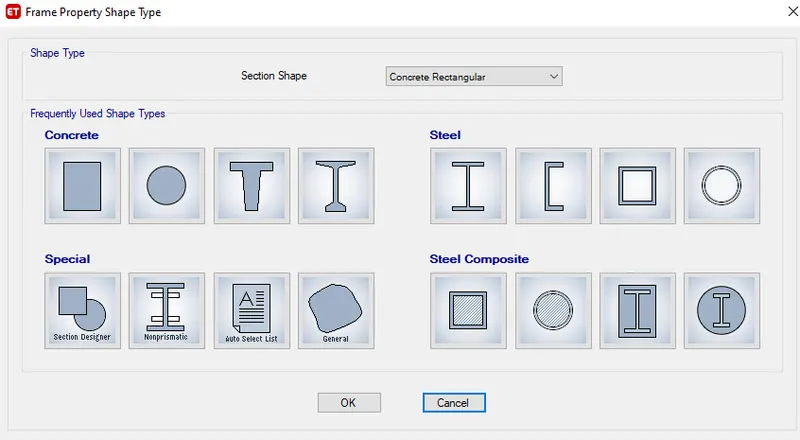
- Now select a shape as required
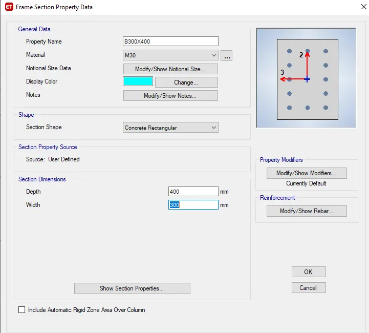
- Now assign the beam size in section dimension
- Now click on Modify/show modifiers
- Now select M3 design only (beam)option
- And select longitudinal as HYSD500 and HYSD415 as confinement bars and click ok
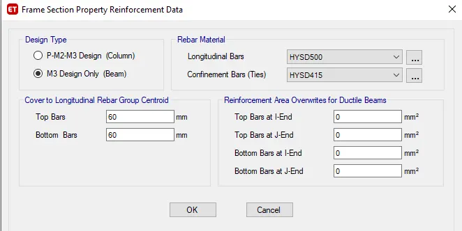
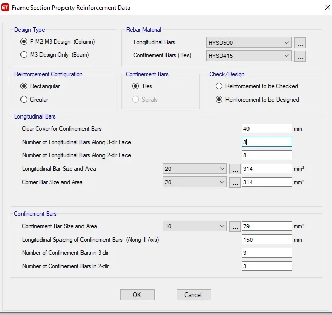
- Follow same steps for column and give dimensions as 800x800
- Now select P-M2-M3design (COLUMN)option
- And select longitudinal as HYSD500 and HYSD415 as confinement bars and click ok
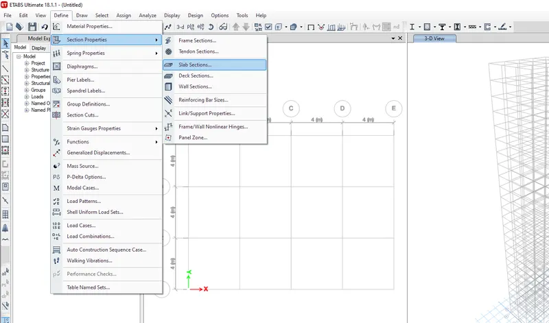
- Now go to define and select section properties and select slab sections
- Now click on add new property
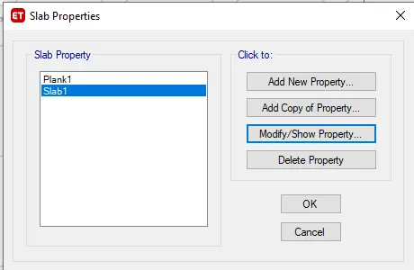
- Now add name as slab 150
- Give thickness as 150 and modeling type membrane and click ok
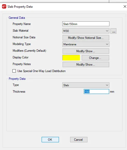
- Now select the quick draw column
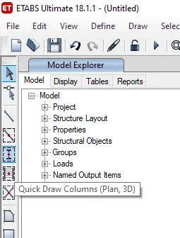
- Now select all stories as shown
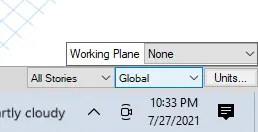
- In properties of object select c800x800
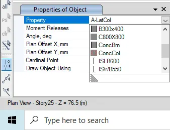
- Now assign the column as shown
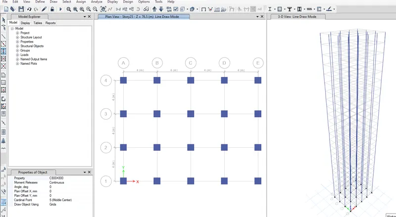
- Similarly, select the beam
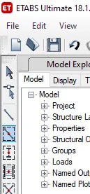
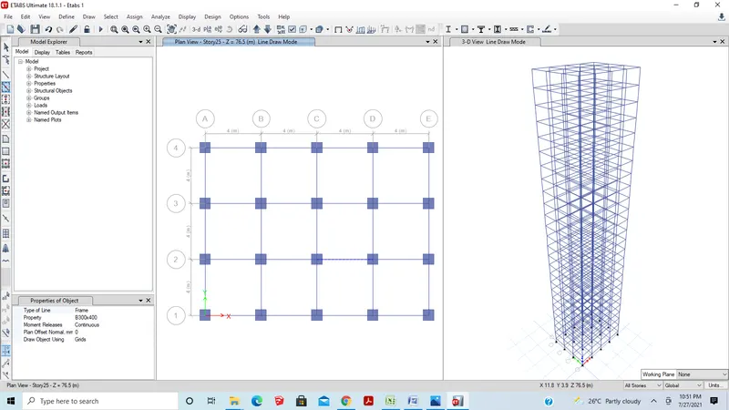
- And assign the beams as shown
- Now select draw rectangular floor or wall and assign the floor as shown
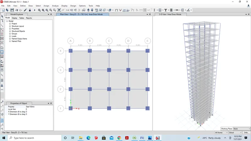
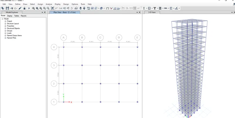
- Now go to the base floor and select all the points
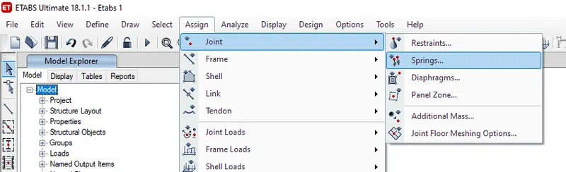
- Now go to assign and joint and select restraints
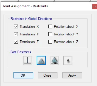
- Now we get joint assignment
- Now select x,y,z translations as shown and click ok
- Now go to define and select load patterns
- Now we get the load patterns tab
- Now add loads as shown below
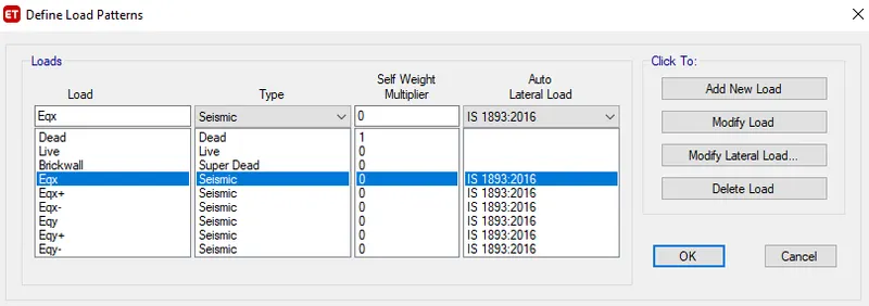
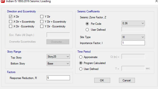
- Now select Eqx and click on modify the lateral load
- Now we get a new tab select site type as III and keep x-dir on as shown
- Similarly with Eqx+, Eqx-,Eqy,Eqy+,Eqy-
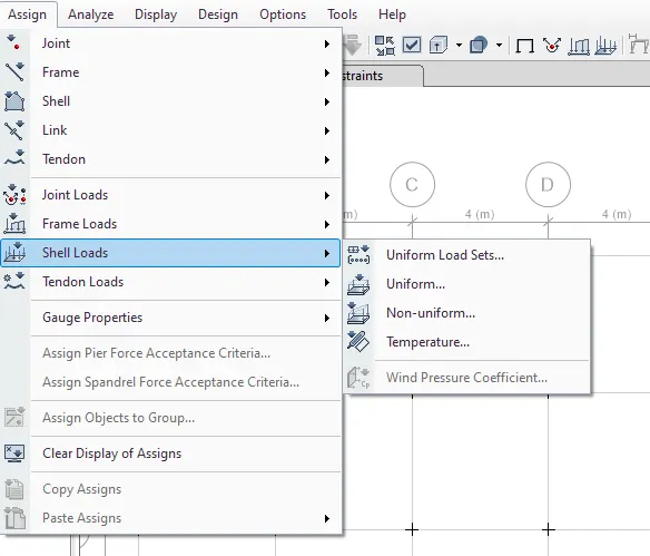
- Now go to assign and select shell loads and select uniform loads
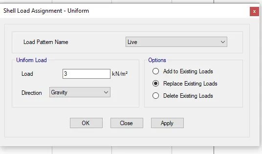
- Select load pattern as live and load as 3 till 24 floor
- Select load pattern as live and load as 1.5 for 25th floor
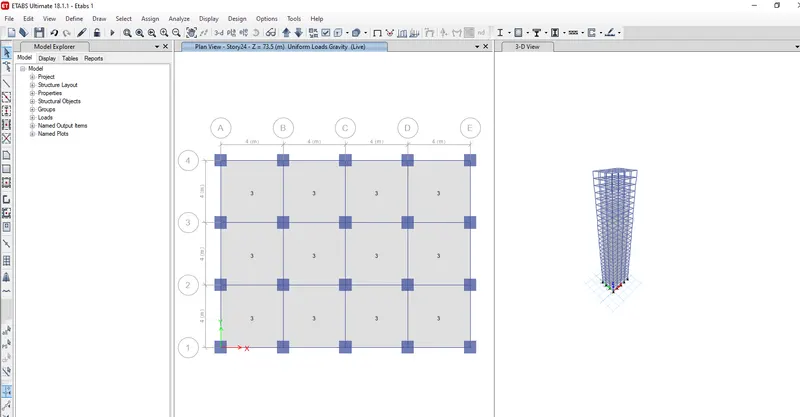
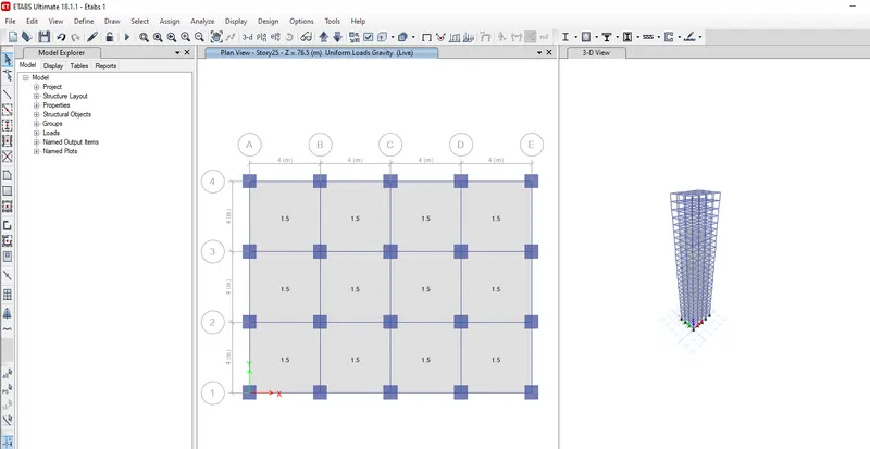
- Now go to select and select and object type
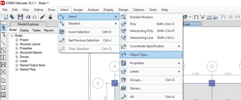
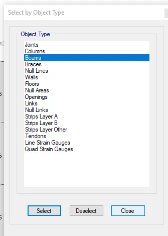
- Now select beams
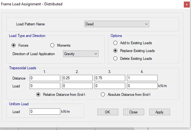
- Now go to assign and select frame loads and distributed
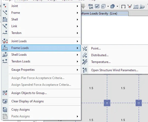
- Give uniform load as 10 and load pattern as a brick wall
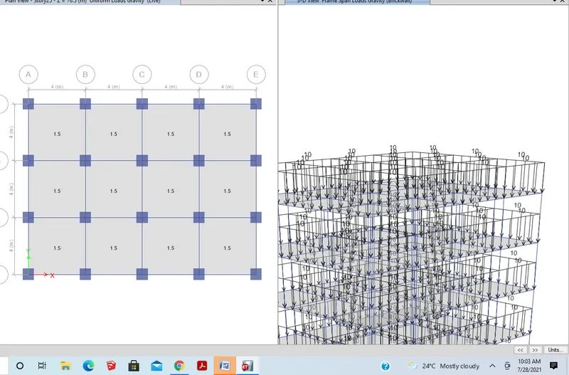
- Now go to define and select mass source
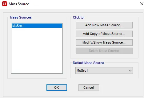
- Now we get mass source tab now select modify/show mass source
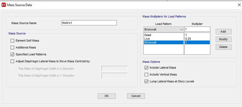
- Now we add load patterns in the mass source data as shown
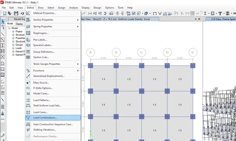
- Now go to define and select load combination as shown
- Now in load combination tab select Add default design combos
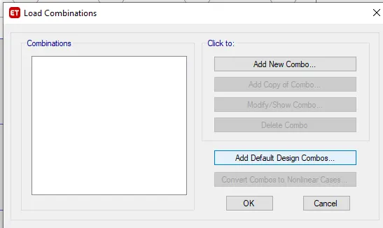
- We select concrete framed design
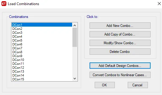
- Now we can see the load combinations as shown
- Now go to select and select and object type
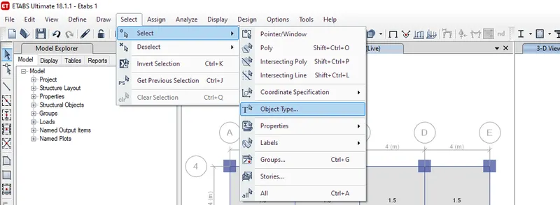
- Now select floors
- Now go to assign and shell and diaphragms
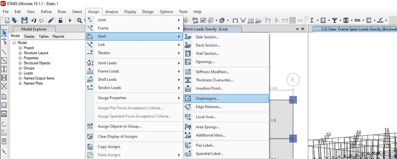
Now we get a shell assignment tab select D1 and ok
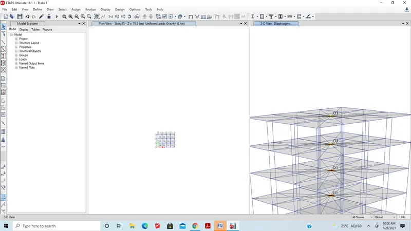
- Now go to analyze and select check model
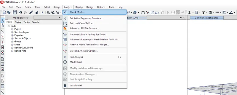
- Now we get check model tab click on select all ok
- Now we get the wanings tab as shown

Now run analysis
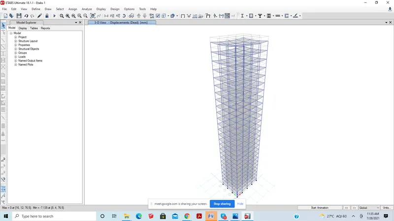
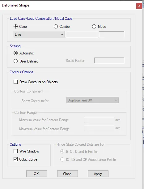
- Now click f6 to get the deformed shapes tab
- Now you will get deformed shapes tab and Now add live load and ok
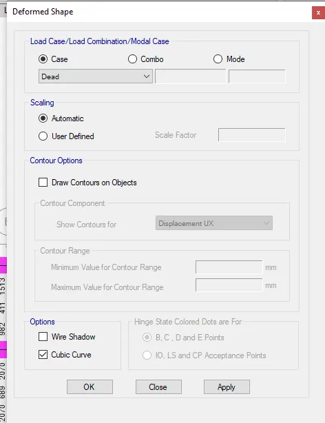
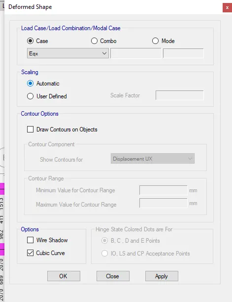
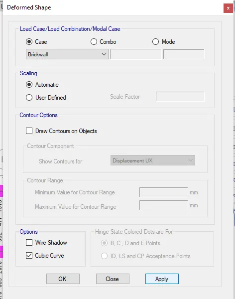
- Similarly, add dead load and Eqx and brick wall loads
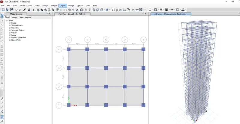
- Now go to display and select show tables
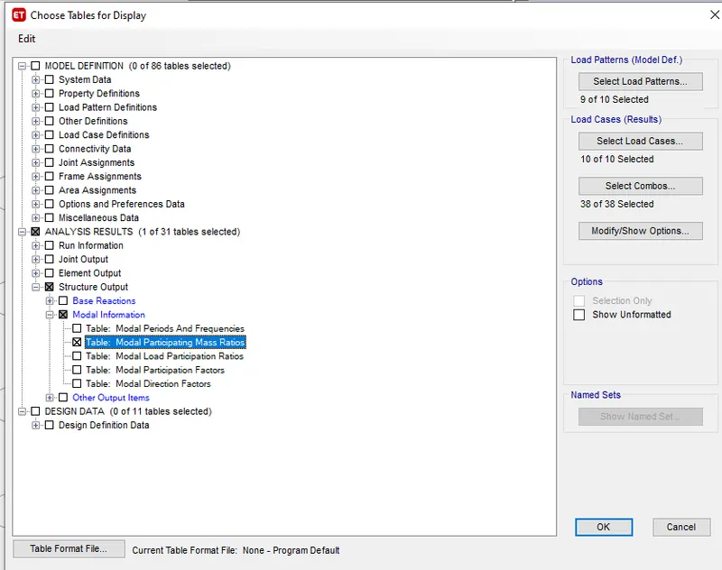
- Now select modal participation mass ratios and click ok
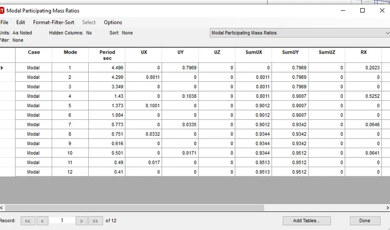
- Now we get modal participation mass ratios table
Result:
- Modeling and analyzing a 25 storey building with the specified properties using ETABS has successfully completed