Creating Kitchen layout, Hatching of Architectural elements and sectional view of an Industrial Building in AutoCad
1ans:
Aim:To create kitchen layout and provide hatches pattern
Procedure:
- First set the units to Decimals and mm
- limits to 0,0 and 1000,1000
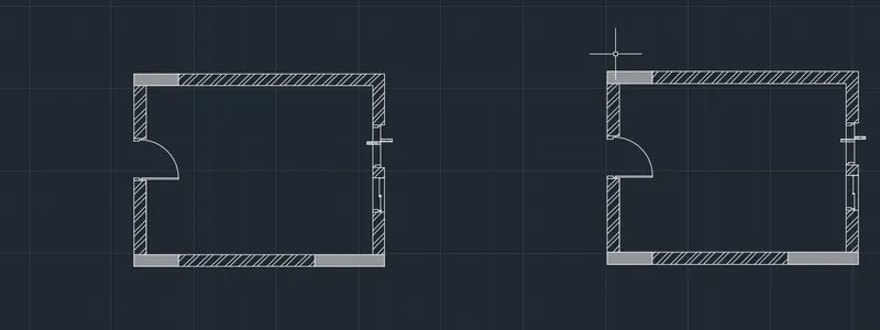
- Now use rec command and draw a rectangle with the dimensions are 4300 X 3200mm.
- Now use the offset command and offset it to the distance of 230mm outside.
- Using arc and line command, doors are drawn.
- Hatch command is used to Hatch the model.
- Now select the total figure drawn and make a copy by using copy command.
- Rectangle command is used to model the refrigerator.
- Now use the offset command and offset it to the horizontal distance of 350,450,900,450,450 and 560.
- Now use the offset command and offset it to the vertical distance of 600
- Now use the trim command to trim the extras.
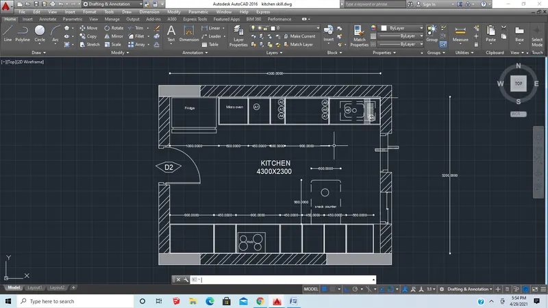
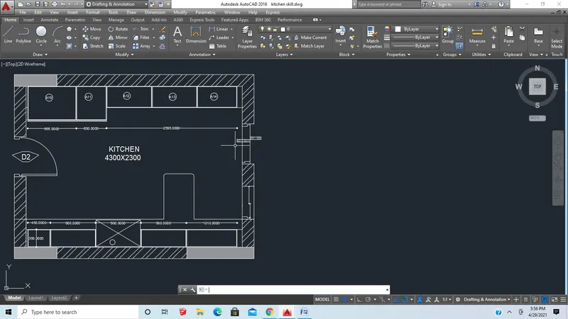
- Now use the line type command and load the dotted lines.
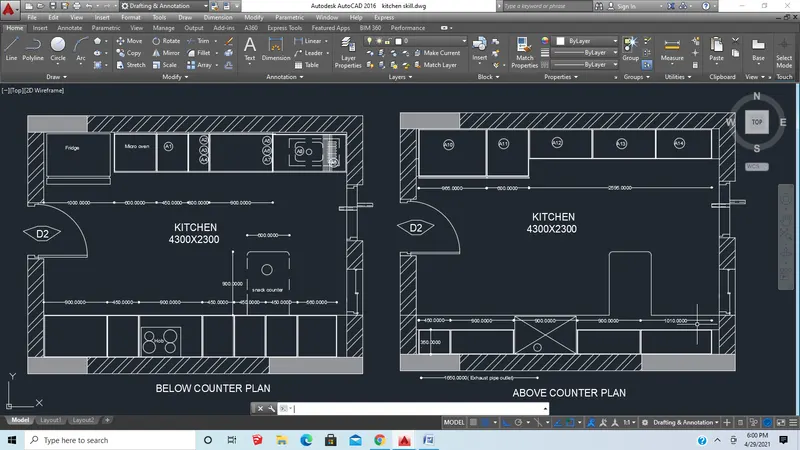
- Now use the text command to text the given annotations.
- Now use the dimensions command to give the dimensions to the plan.
- Now use the leader command for naming the dimensions.
Result:
2 ans:
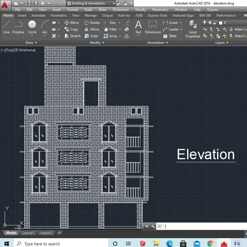
Aim: To Create the elevation of the plan created in Challenge 7 and apply proper hatch in the walls, doors,
windows, and other architectural elements.
INTRODUCTION:
- Elevation drawings are a specific type of drawing architects use to illustrate a building or portion of a building.
- An Elevation is drawn from a vertical plane looking straight on to a building facade or interior
- This is as if you directly in front of a building and looked straight at i
- Elevations are a common design drawing and technical architectural engineering convention for graphic representation of architecture.
- Elevation drawings are orthographic projections, This means they are not drawn in perspective and there is no foreshortening.
Procedure:
- First, we have to open the AutoCAD
- Now set the units to Decimals and mm
- limits to 0,0 and 1000,1000
- Next, we draw the architectural elements using the line command, rectangle command,fillet and offset command.
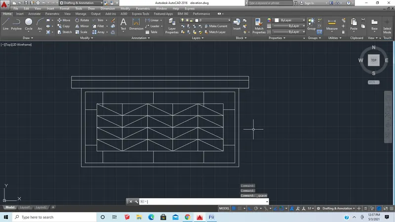
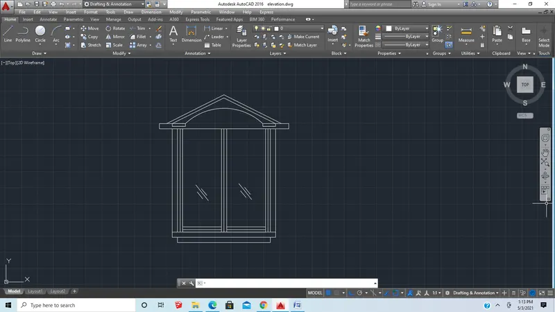
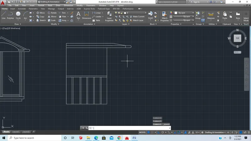
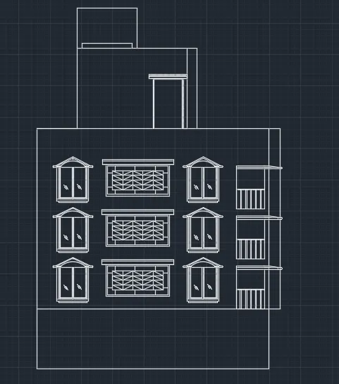
- Coming to the drawing of the elevation of the residential building, first, we draw the horizontal line using the line command with the length of 11574mm.
- Next, we need to draw another line from the previous line vertically with a length of 12000mm.
- Next, we have to draw the line horizontally backward from the previous line with the length of 12150mm at the top.
- Next, we draw the line downwards vertically with the length of 12000mm, by drawing the last line the rectangle will be
- Next, we draw the rectangle at the top of the building.
- And again we draw another rectangle on the previous rectangle with the lengths given in the given drawing.
- Next, we draw the three rectangles at the bottom of the rectangle with different dimensions.
- Next, we need to draw the sunshades provided in the drawing
- Next, we draw the windows with standard construction dimensions with the help of line command and arc command.
- Next, draw the balcony part using the line command, offset command and trim command.
- Next, we need to use the single text command to enter the text downside the elevation.
Result:
3 ans:
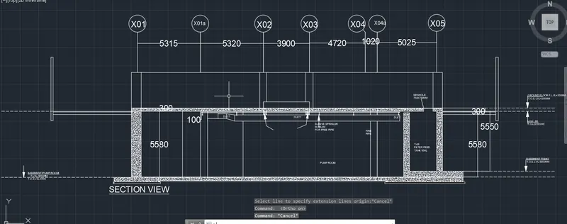
Aim: To Create the section view of an industrial building
Procedure:
- First, we have to open the AutoCAD
- Now set the units to Decimals and mm
- limits to 0,0 and 1000,1000
- First, we have to draw the X-line at any point on the screen
- Next offset the line to top to a distance of 5850mm and we have to do offset of last offset line to the distance of 3000mm to the top
- Next, we have to draw the vertical X-line on any point on the horizontal line
- Next, do offset of line to the right to a distance of 10635mm
- Next offset the last line with a distance of 3900mm to the right
- Next offset the 1st line with the distance of 5740mm to the right side.
- Next, we do the offset for the last line with the distance of 5025 to the right side.
- Offset the left and right edges with a distance of 500mm.
- Next, we have to trim the outer edges using the trim
- Next offset the bottom edge of the top floor to a distance of 30mm.
- Next offset the last line with a distance of 70mm to the bottom.
- Next offset the last line with the distance of 100mm to the bottom.
- Next, we draw the sprinkler pipe along with the duct pipe.
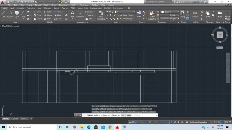
- The duct pipe thickness is 300mm and the thickness of the sprinkler pipe is 100mm.
- Next, we draw the manhole cover with the thickness of 750mm at the right top edge of filter feed walls as shown in the figure.
- Next, we draw the thickness of the pump room slab with the different layers using the line command.
- Next, we need to draw the circle with a radius of 5OOmm and enter the text in the circle as given in the figure
- Next, we need to use the single text command to enter the text where ever required in the section view of the industrial drawing.
- Finally, we use the hatch command to hatch the walls and floor slabs as drawn in the below figure
- Finally, we have to use the dim linear command to put the dimensions wherever required in the drawing.
RESULT:
FINAL RESULT: