Creating 3D Isometric view of various structural elements in AutoCAD
1 ans:
Aim: To Create a 3D Isometric View of the building with plan and elevation
Procedure:
- Open Autocad 3d
- set-top view
- Set units to engineering and inches
- set limits to 0',0' and 100',100'
- Now use rec command to draw a rectangle of size 10'9"x10'9"
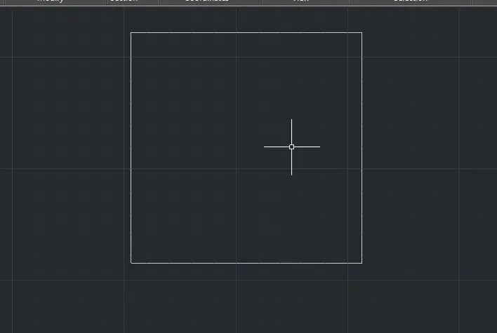 '
'
- Now make a offset of 9" inside as shown
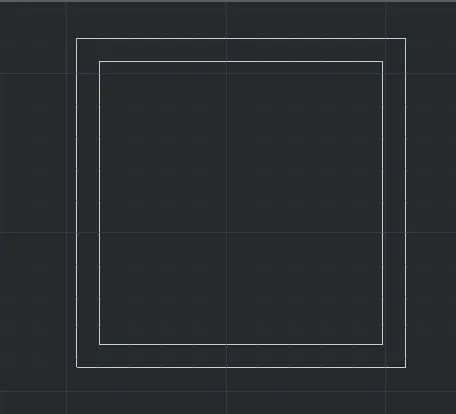
- Now trim both lines and extend the line to the outer rectangle
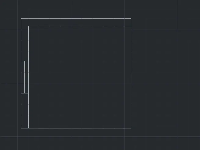
- Now draw windows as shown
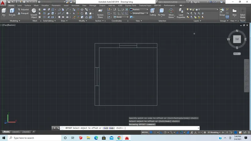
- Now give dimension using dim command
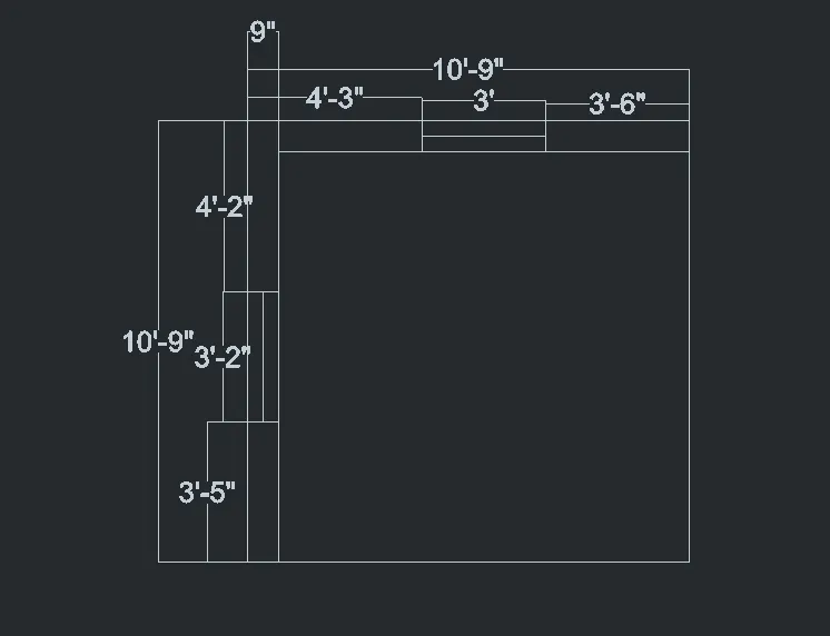
- Now by using 3d face command make 3d face to all
- Now extrude the walls and move the windows up as dimension
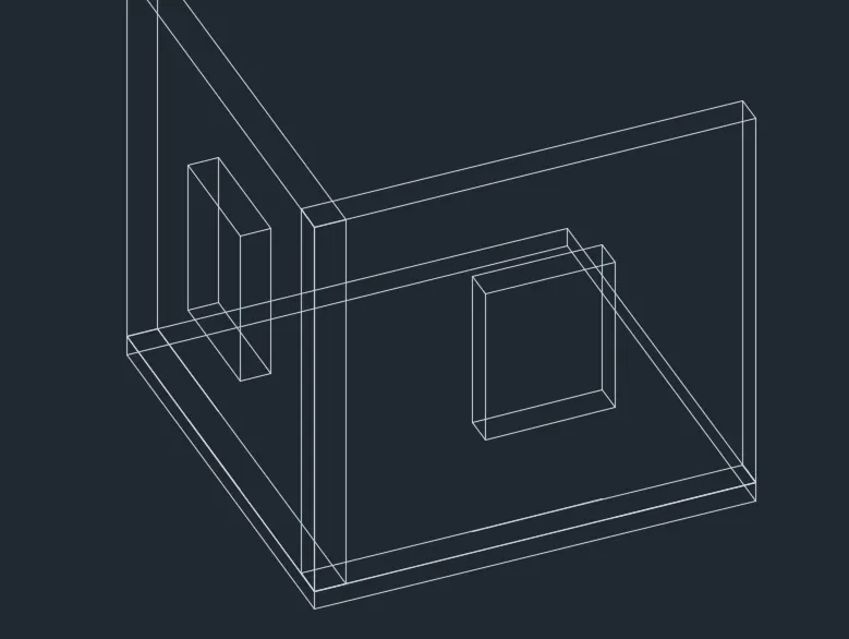
- Now select any wall face and modify the window and give dimensions
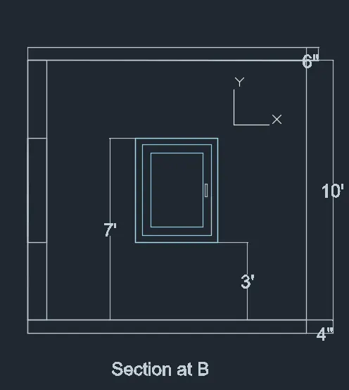
- Now select another wall face and modify the window and give dimensions
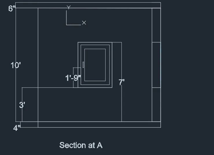
- Now apply layers and keep them in isometric view
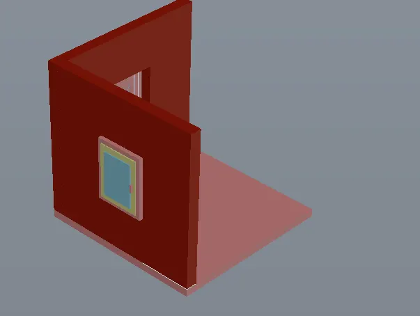
Result:
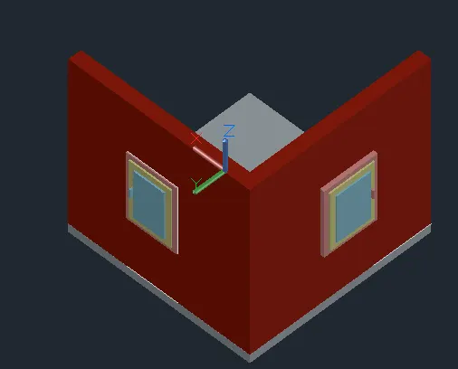
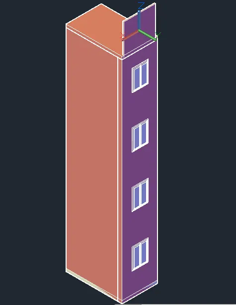
2 ans:
Aim: To Create the 3D View of the Building Façade as given in the plan and elevation and detail of the window.
Procedure:
- Open Autocad 3d
- set-top view
- Set units to engineering and inches
- set limits to 0',0' and 100',100'
- Now use rec command to draw a rectangle of size 10'9"x6'9"
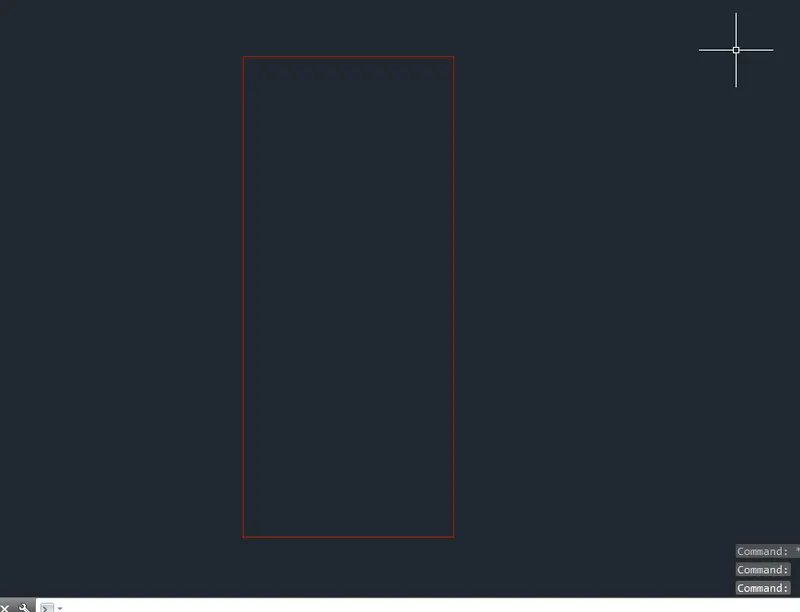
- Now make a offset of 9" and trim the extra line
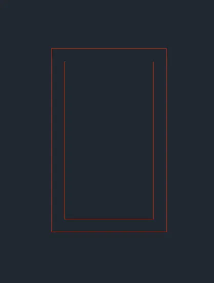
- Now extend the trimmed line till the outer rectangle
- Now draw a window and give dimensions
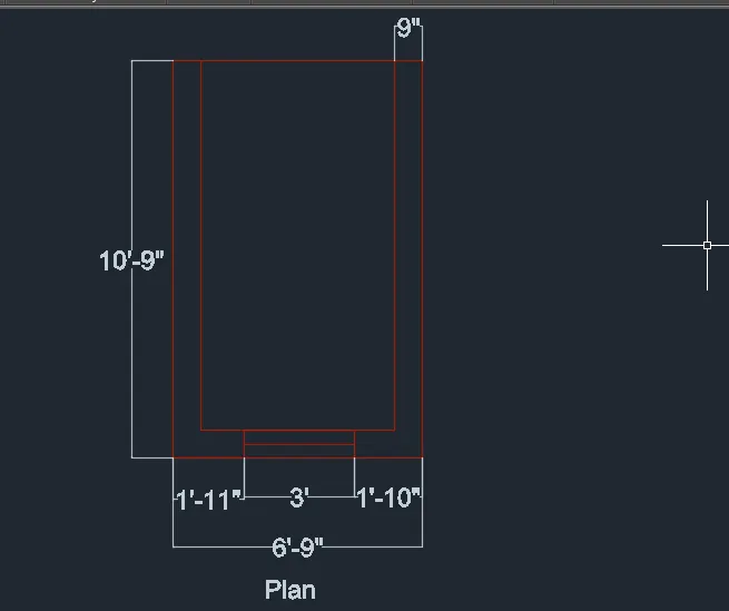
- Now draw the window detial and give dimensions
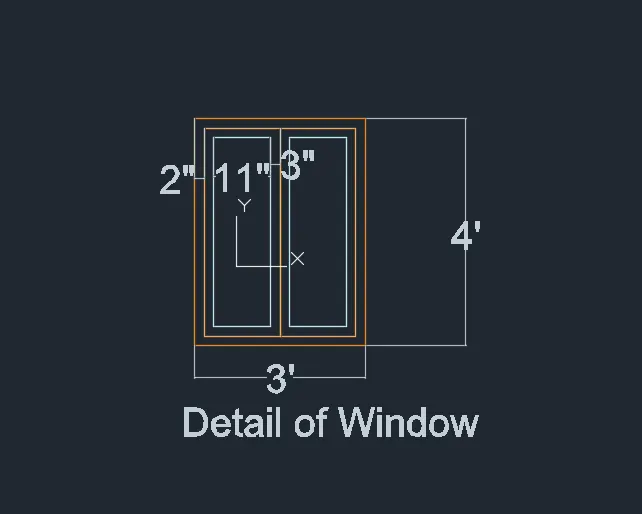
- Now extrude the drawn plane and keep it in a front view and place this window drawn at given heights as shown
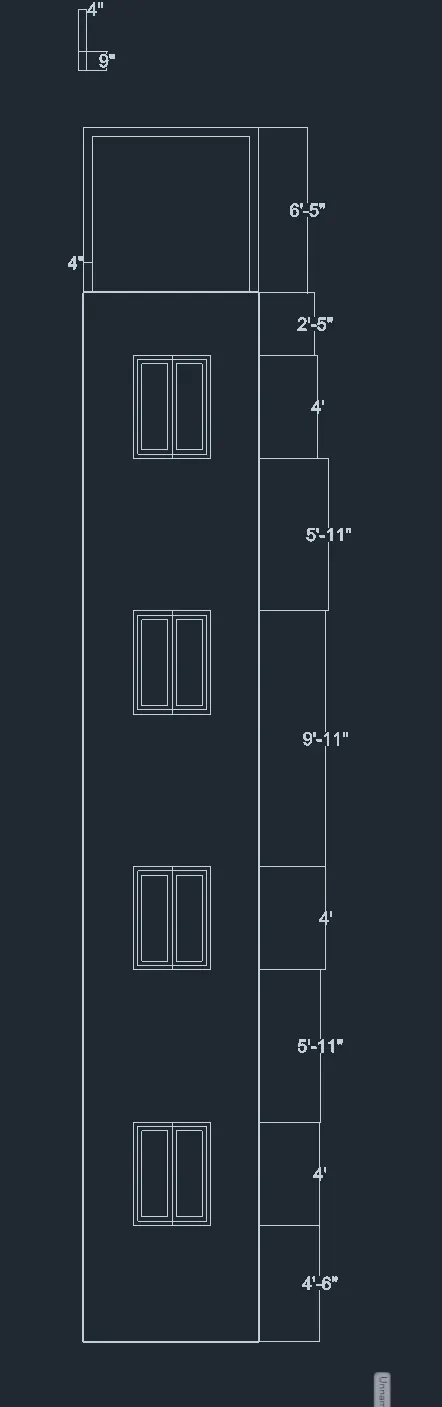
- Now press home button near Ucs to make it as isometric view
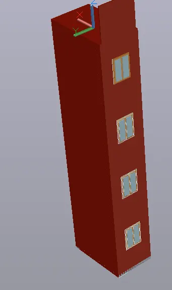
Result:
3 ans:
Aim: To Create the isometric 3d view of a stair with a railing
Procedure:
- Open Autocad 3d
- set-top view
- Set units to engineering and inches
- set limits to 0',0' and 100',100'
- Now use the line command and draw a line of 12' vertically
- Now make a 3' offset for the 12' line
- Now join the two vertical lines at the bottom with a horizontal line
- Now make 9 offset line at 1' distance between each line
- Now after 9 offsets make the offset distance to 3' and draw an offset
- Now give dimensions as shown
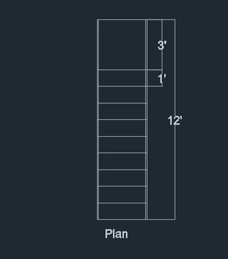
- Now by using the line command draw the side elevation and give dimension as shown
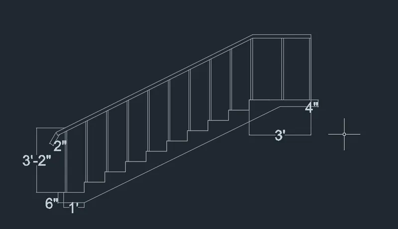
- Now remove the railing and keep it in isometric view and extrude the stairs as shown
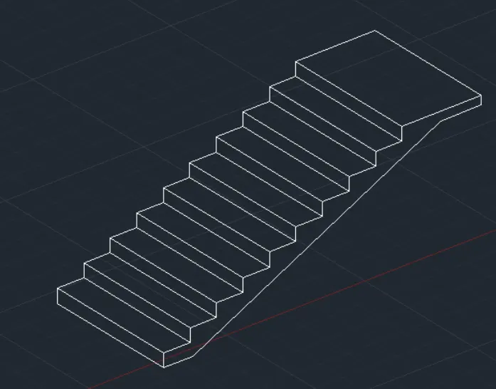
- Now apply layer
- Now by using the circle command and extrude command, we draw the railing as shown
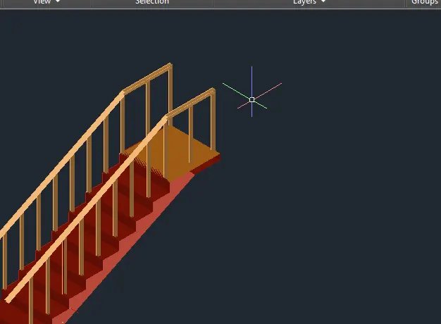
Result:
4 ans:
Aim:To create the 3D view of a Wall with spread footing
Procedure:
- Open Autocad 3d
- set-top view
- Set units to decimals and mm
- set limits to 0,0 and 100,100
- Now use the line command and draw a line of 7500 vertically
- Now make an offset of 670
- Now join two vertical lines in up and down using the horizontal lines
- Now make 3300mm offset for horizontal lines in top and bottom
- Now make offset for the vertical line as reqiured
- Now draw a Door as shown
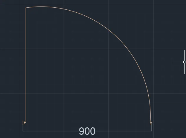
- Now place this door in the wall as shown
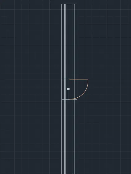
- Now hatch the wall as required and give dimension
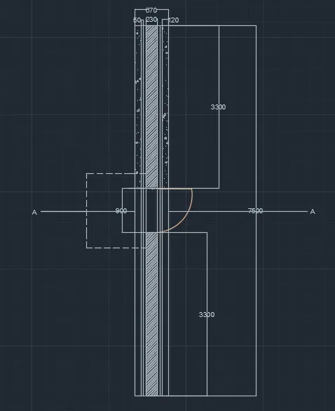
- This is the top view
- Now we are drafting the section of the wall footing
- Now by using line command and rectangle command the section of the wall footing is drawn
- Now give hatching where ever required
- Now give dimensions
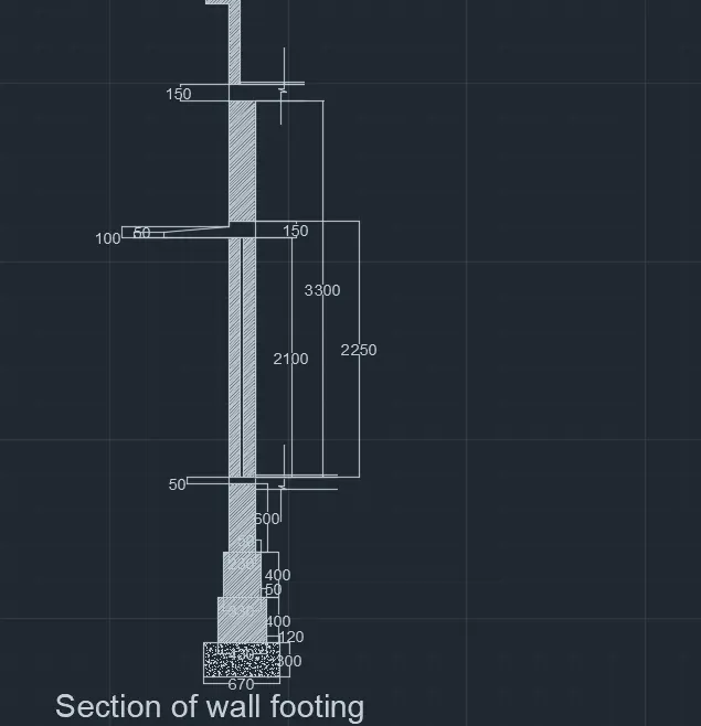
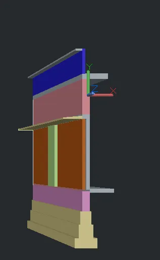
- now keep in isometric view and extrude the section and apply layers as shown
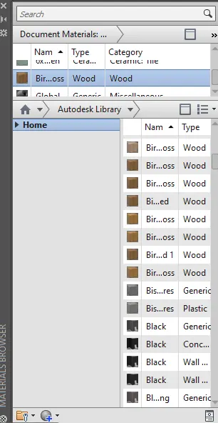
- Now go to ribbon bar and open visualization bar and go to the material browser and select the materials
- Now apply the selected materials to the section and make a render using render command
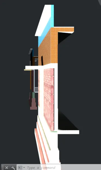
- Use the camera command to take a picture

Result:
Final result: