Creation of Column Schedule and Drawing Template using AutoCad
1 ans:
Aim: To create a column schedule
Procedure:
- Open AutoCAD
- Open AutoCAD Select new and Imperial system
- Select Engineering with precision 0'-0.0"
- SET LIMITS AS 0’,0’ and 100’,100’
To draw column:
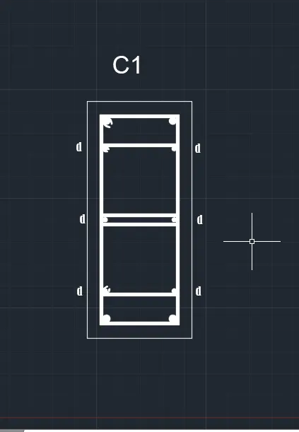
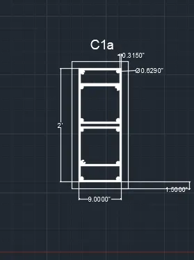
- Type Command LINE and draw 9" horizontal line and 24" vertical line on both sides
- Type Command OFFSET and draw an offset of 0.6" on all 4 sides
- Type Command TRIM and trim the unwanted lines
- Type Command DDPTYPE and select a suitable point type
- Type Command DIVIDE and divide the line into 5 segments into 24" of both sides
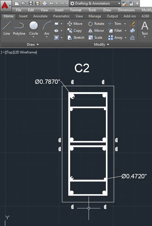
- Type Command CIRCLE of the diameter of 20mm=0.79" of 4 numbers at a suitable place
- Type Command CIRCLE of the diameter of 12mm=0.472" of 6 numbers at a place where a is marked
- Now use fillet of radius 0.3” at 4 corners
- Type Command TEXT of height 8" and style of Roman.shx and angle of 0 degree and type 9"X24",M25, 4 20dia( type %%C for diameter)
- Command L weight and draw stirrups of 8mm dia at the required places
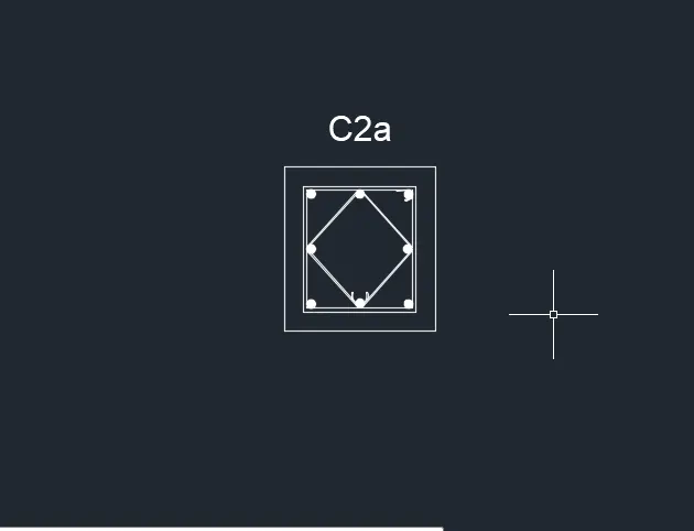
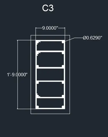
For the table:
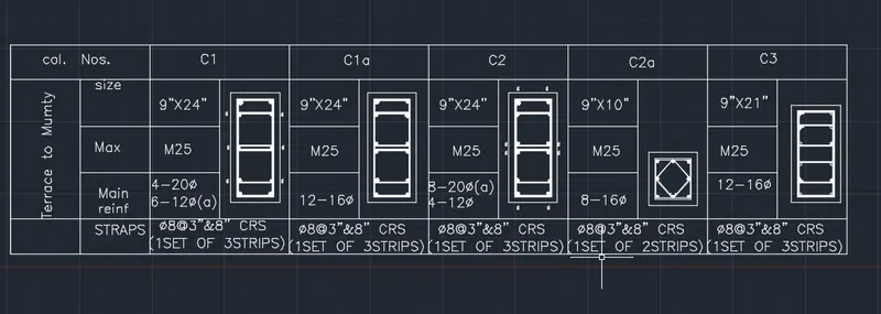
- Command LINE and draw a line like a table and place the diagram in suitable places and type the text.
- Type Command TEXT and selecting a single line text of height of 8" and angle of 90 degrees and type TERRACE OF MUNITY
- Type Command TEXT and selecting a single line text of height of 8" and angle of 0 degrees and type COL NOS, SIZE, MIX, MAIN RDNF, and STRIPS
- Command SCALE and scale the diagrams
Result:
2 ans:
Aim: To Create a window schedule
Procedure:
- Open AutoCAD
- Open AutoCAD Select new and Imperial system
- Select Engineering with precision 0'-0.0"
- SET LIMITS AS 0’,0’ and 100’,100’
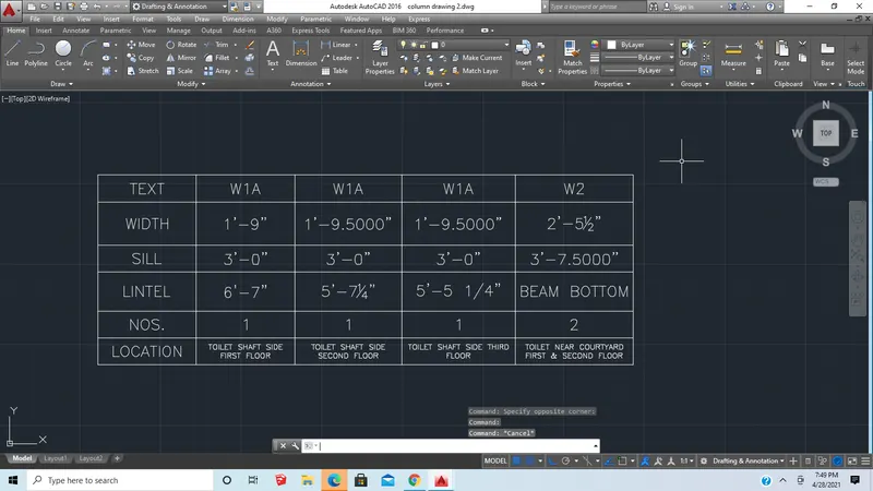
- Type Command TABLE without title and header with 5 columns and 6 rows as shown below
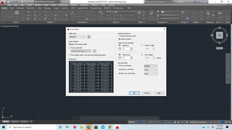
- Type TEXT and enter the relevant texts on the relevant columns and rows
- Type Command TEXT of height 8" and style of Roman.shx
Result:
3 ans:
Aim: To Create the drawing template:
Procedure:
- Open AutoCAD
- Open AutoCAD Select new and Imperial system
- Select Engineering with precision 0'-0.0"
- SET LIMITS AS 0’,0’ and 100’,100’
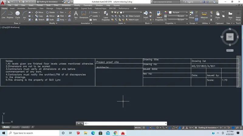
- Now by using the line command draw table as required(shown)
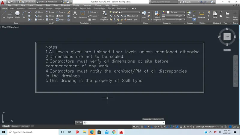
- Now by using the Mtext command write the text required
- Type Command TEXT of height 8" and style of Roman.shx
Result:
4 ans:
Aim:To Create the list of drawing schedule
Procedure:
- Open AutoCAD
- Open AutoCAD Select new and Imperial system
- Select Engineering with precision 0'-0.0"
- SET LIMITS AS 0’,0’ and 100’,100’
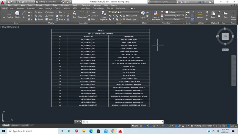
- Type Command TABLE with 2 title and data with 3 columns and 26 rows as shown below
- Now fill in the details as given by using text command
Result:
5 ans:
Aim: To Create the Beam detail
Procedure:
- Open AutoCAD
- Open AutoCAD Select new and Imperial system
- Select Engineering with precision 0'-0.0"
- SET LIMITS AS 0’,0’ and 100’,100’
- Command LINE drawing a vertical line and 12" of a concrete portion including in it
- Command OFFSET of 6" to that vertical line
- In Express tool Tab selecting the Break-line symbol and specifying two-point to break the line on both sides
- Command HATCH and selecting AR CONC and selecting the concrete portion to hatch
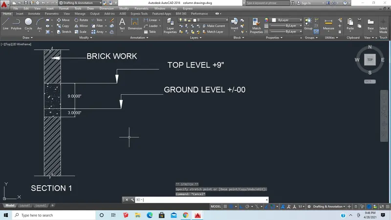
- Selecting multileader style manager and modify in leader structure and making 2 as maximum leader points and type BRICKWORK
- Selecting multileader style manager and modify in leader structure and making 3 as maximum leader points and type TOP LEVEL +9" and GROUND LEVEL +/-00
- In annotating tab selecting manage dimension style and in symbols and arrows changing arrowheads to Architectural tick
- Command DIMLINEAR and dimensioning the concrete portion
Result: