Creating a 3D rendered model for a Residential Building in AutoCad
Aim: To create a 3 dimensional model of the residential building with a rendered view.
Introduction:
- 3D computer-generated images of proposed building projects and other types of constructions are widely used by architects and designers to showcase their designs to clients.
- The steady advancement in computer graphics has enabled the creation of realistic 3D commercial rendering for building projects.
- Commercial rendering has become ubiquitous in the real estate
- Both small and mega commercial companies want to see their future buildings 3D architectural renderings before giving the contracts to architects and builders.
Commands used:
COMMANDS USED FOR DRAWING THE 3D RENDERED VIEW OF THE BUILDING ARE AS FOLLOWS.
Extrude- Location: Draw > Modeling> Extrude
This AutoCAD 3D Extrude command allows the user to create a 3D object by extruding a 2D face along a line or path.
Sweep- Location: Draw > Modeling> Sweep
This command helps the user to extrude the 2D objects without the 2D face being orthogonal to the beginning of the path.
Union- Location:Modify > Solids Editing> Union
This AutoCAD 3D command allows the user to combine two objects converting them into one single object
Subtract- Location:Modify > Solids Editing> Subtract
This command is opposite to the union command; this command works when there is a common area in both the objects. Then this command subtracts object A from object B.
Intersect- Location:Modify > Solid Editing> Intersect
With this AutoCAD 3D command the user is left with the area that is common to both the objects.
Revolve- Location:Draw > Modeling> Revolve
This AutoCAD 3D command creates a 3D solid by revolving a 2D object around an axis.
- Line command
- Rectangle command
- UCS command
- Dimlinear command
- Dimaligned command
- Region command
- Extrude command
- Subtract command
- Box command
- Units command
- Dimstyle command
- 3Dface command
- 3Dorbit command
- Hide command
- Explode command
- Move command
- Copy command
- Dist command
- Solidedit command
- Union command
- Boundary command
- 3Dmirror command
- 3Drotate command
- Erase command
Procedure:
- First, open an AutoCAD 3d
- Now set units as Engineering and inches
- Now set limits to 0',0' and 100',100'
- Now set to top view
- Now we have to set the layers
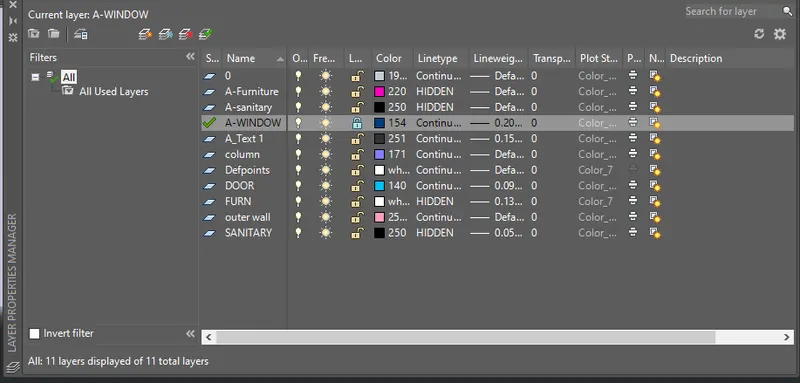
- Create everything in separate-separate layers so that it is easy to modify the plan
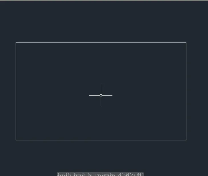
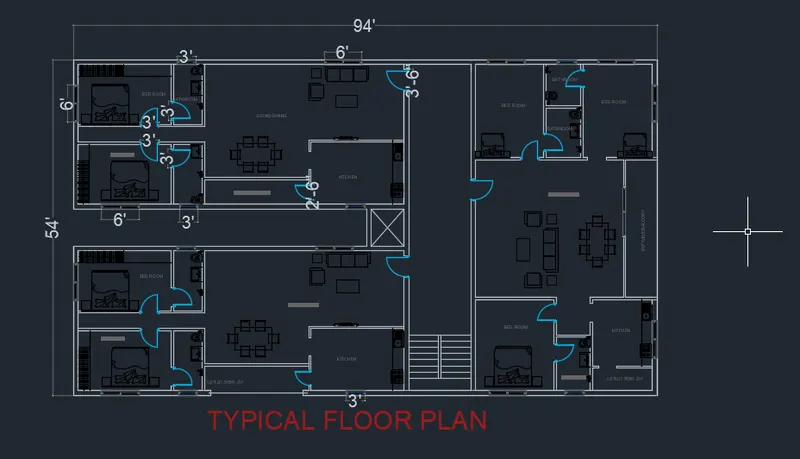
- First, draw a rectangle of size 94'x54'
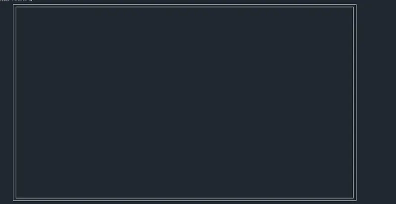
- Now make an offset of 9"
- Now by using line command and rectangle draw the inner lines
- and place windows and columns and place it as shown
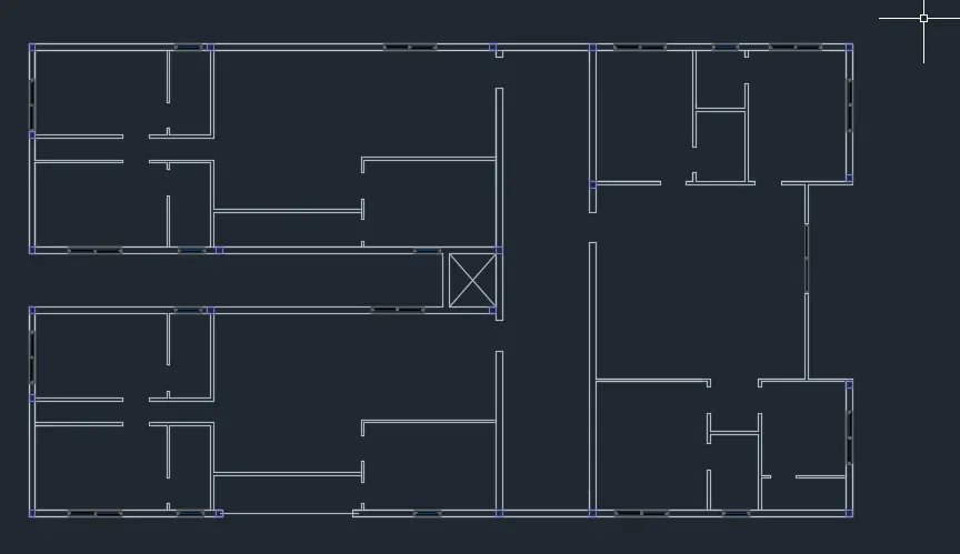
- sizes of windows are 6'x4' and 3'x2'
- sizes of doors are 3'x6'11" and 3'6"x6'11" and 2'6"x6'11"
- Now create doors and place furniture and place it
- Now lock all layers and open only column layers
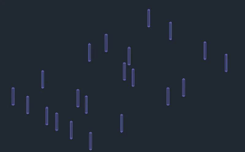
- Now copy all the columns and paste them in another place on the screen
- Now extrude the columns as shown
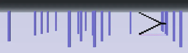
- Now draw the stairs in between the columns
- Now extrude one stair and copy that stair and place it at top corner to do it place it in isometric view
- Now keep it in top view and 2d wireframe and draw a rectangle leaving the stairs area
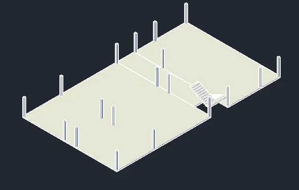
- Now copy these total columns and floor and paste it above till four floors as shown
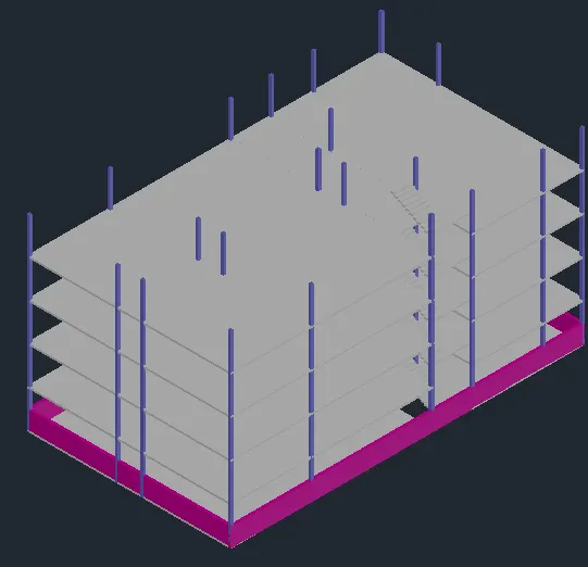
- Now extrude 2d floor plan as shown
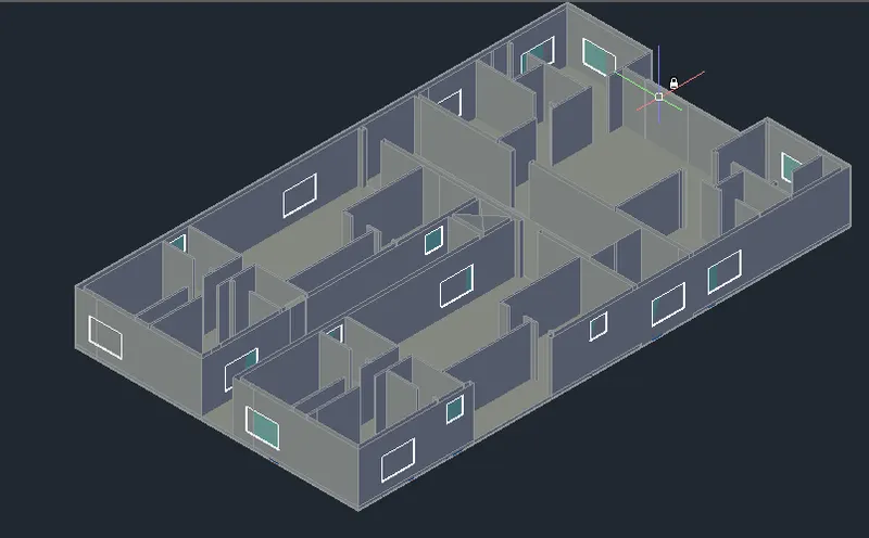
- Now select the total 3d floor plan and use the copy command
- Now place this floor plan on the first floor to the 4th floor of the column plan as shown
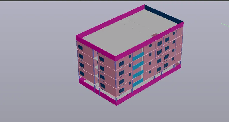
- Now keep it on top view and draw a rectangle and extrude it to get a water tank
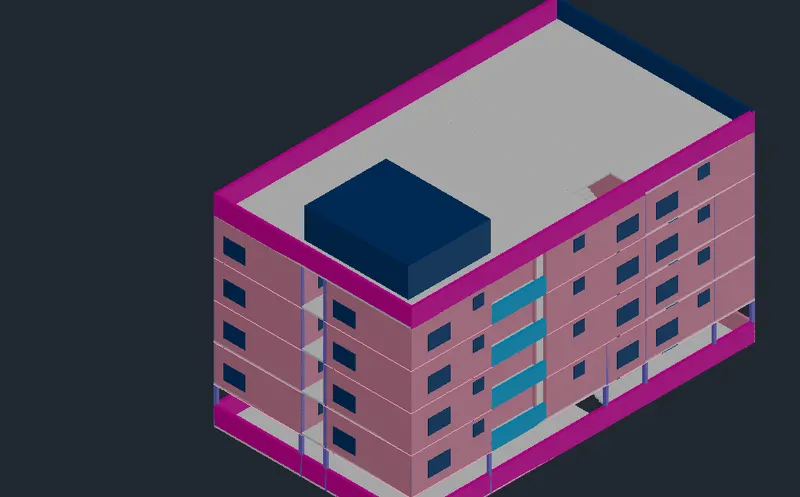
Different views of building
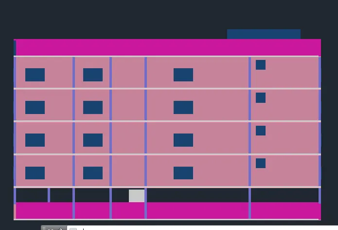
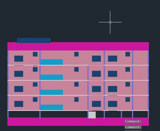
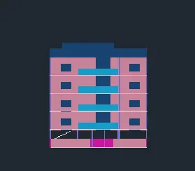
- Now go to the ribbons tab and visualization tab now open materials bar
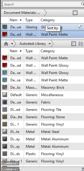
- Now apply the materials as we need
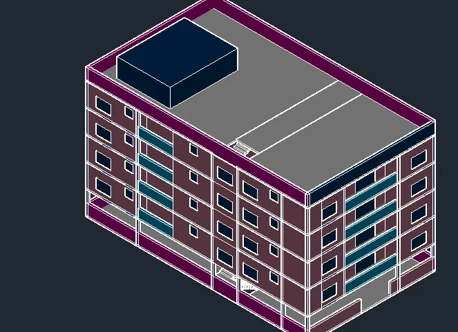
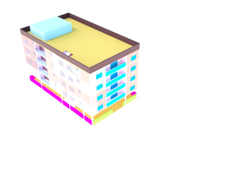
- Now render the image using the render command
- This render is before applying materails
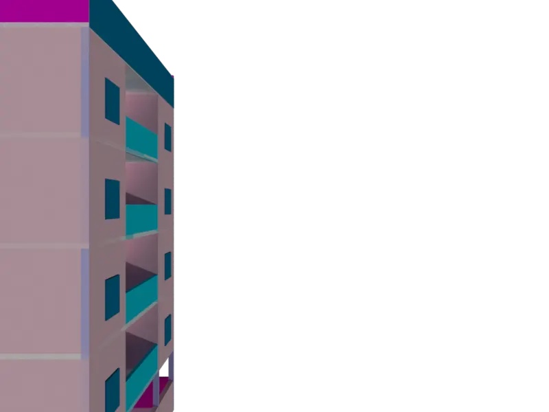
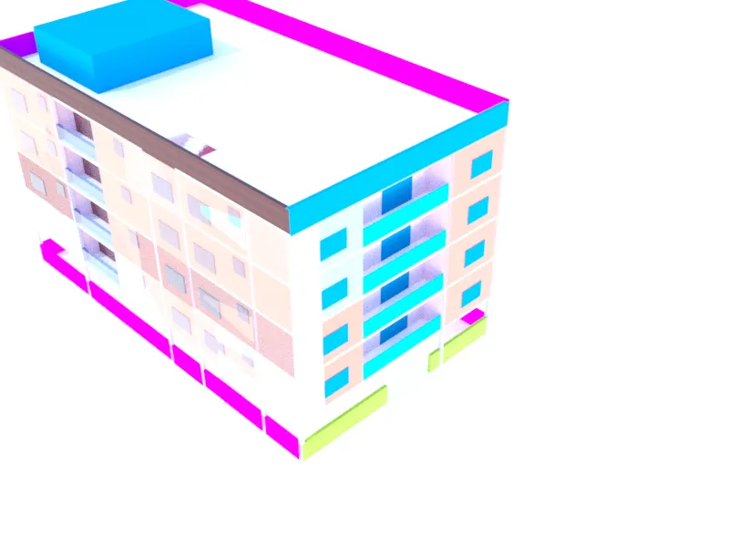
- After applying the materials
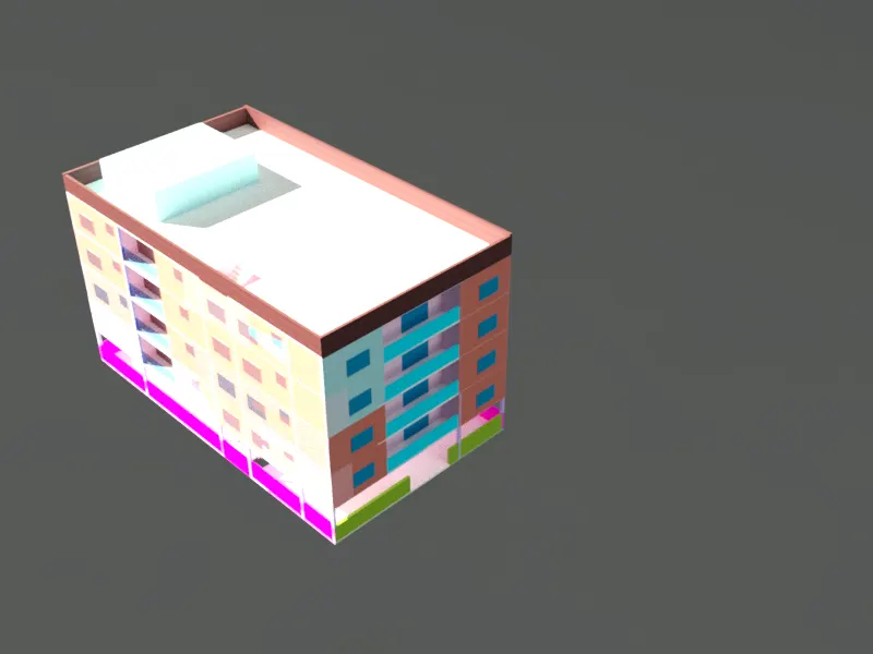
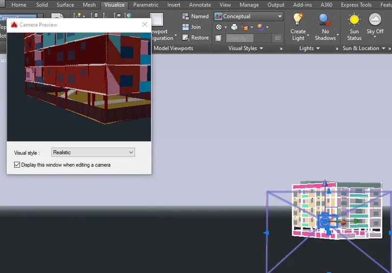
- Now use the camera command to take a photo
Result: